TM4C123G Clock Setup Tutorial – Configure System Clock with PLL
The system clock is the heartbeat of any microcontroller. It determines how fast the CPU executes instructions, how timers count, and how peripherals like UART or SPI communicate. By default, the TM4C123G LaunchPad runs from its internal oscillator, but to achieve accurate timing and better performance, we usually configure the clock using the PLL (Phase-Locked Loop).
In this tutorial, we’ll learn how to set up the system clock on the TM4C123G using the TivaWare™ Peripheral Driver Library, specifically with the SysCtlClockSet() function.
Understanding Clock Sources in TM4C123G
The TM4C123G microcontroller offers flexible options for generating the system clock, which controls how fast the CPU executes instructions and how peripherals operate. Choosing the right clock source is essential for accuracy, power consumption, and overall performance. The main clock sources include:
1. Main Oscillator (MOSC)
- The main oscillator allows the MCU to use an external crystal or resonator.
- Typical crystals include 8 MHz, 16 MHz, or 25 MHz.
- External crystals provide high accuracy, making them ideal for applications where precise timing is critical, such as UART communication or sensor interfacing.
- The main oscillator can be combined with the PLL to achieve higher system clock frequencies.
2. Internal Oscillator
- The TM4C123G has a built-in 16 MHz precision internal oscillator.
- It is convenient because it requires no external components.
- While suitable for many general-purpose applications, the internal oscillator is less accurate than an external crystal, especially over temperature or voltage variations.
3. Phase-Locked Loop (PLL)
- Most applications, including timing-sensitive peripherals and high-speed processing, benefit from using the main oscillator with PLL enabled.
- The PLL is a hardware multiplier that increases the frequency of the oscillator to a higher system clock.
For example, the TM4C123G can use the 16 MHz main oscillator with the PLL to reach a system clock of up to 80 MHz. Using the PLL allows high-performance operation without needing a high-frequency crystal.
We will cover all three clocks in this tutorial, exploring their sources, how they operate, and how to configure them.
Setting up the Project
I have already explained how to create a new project in TM4C123 using CCStudio. You can create a similar project with blinky template and then modify it for this tutorial.
There are only 2 things we need to do to turn the blinky template into a new project:
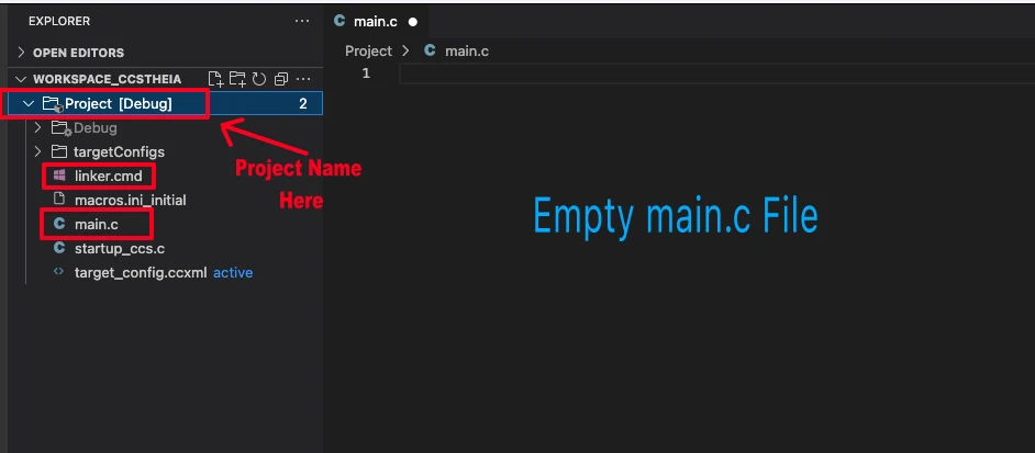
- Delete everything from the blinky.c file, so it should be completely empty. We will write everything ourselves.
- Rename the following:
- blinky.c → main.c, indicating that this is the main file for the project
- blinky_css.cmd → linker.cmd, indicating that this is the linker file
- blinky (Folder) → projectName (Folder)
The final modified project is shown in the image below.
Using the Main Oscillator (MOSC) for Clock
Let’s start with the main oscillator first. As mentioned earlier, the main oscillator allows the MCU to use an external crystal or resonator. Typical crystals include 8 MHz, 16 MHz, or 25 MHz.
The TM4C123G LaunchPad™ Evaluation Kit has 16MHz on board oscillator crystal. We will first see how to use this crystal to directly provide the clock to the MCU.
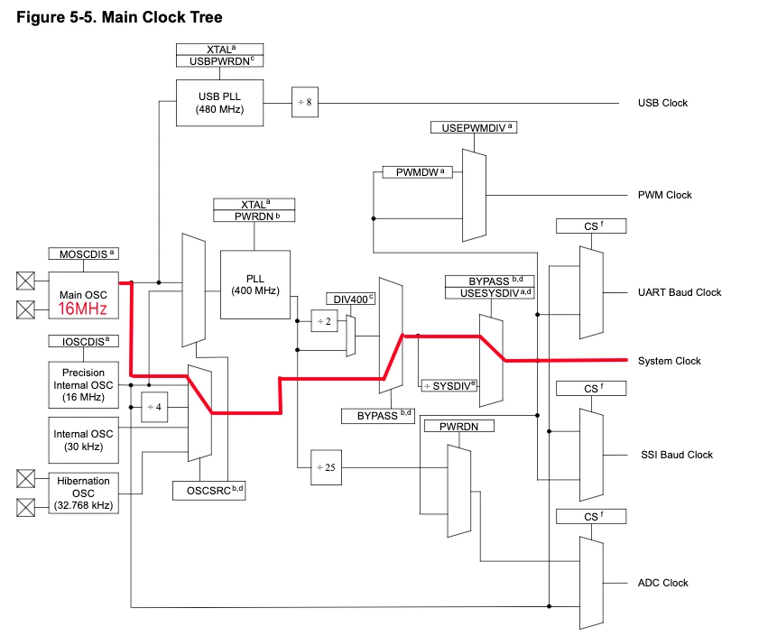
The image below shows the clock diagram for TM4C123G and how the system will be clocked directly from the 16MHz external (Main) oscillator.
Include the required files
We will start with the necessary inclusions in the main.c file.
#include <stdint.h>
#include <stdbool.h>
#include "inc/hw_memmap.h"
#include "driverlib/debug.h"
#include "driverlib/gpio.h"
#include "driverlib/sysctl.h"These inclusions serves the following purposes:
<stdint.h>and<stdbool.h>→ provide standard integer types (uint32_t) andbool."inc/hw_memmap.h"→ contains base addresses for all peripherals (like GPIO ports)."driverlib/debug.h"→ enables debug/error handling support."driverlib/gpio.h"→ functions for configuring and controlling GPIO pins."driverlib/sysctl.h"→ system control functions (clock, power, enabling peripherals).
Configure system Clock
void SysCtlClockSet(uint32_t ui32Config); is the TivaWare function to configure the system clock. The ui32Config parameter is a combination of macros that define:
- Desired system divider.
- The clock source (main oscillator, internal oscillator).
- Whether PLL is used or bypassed.
We will write a new function to configure the system clock. In this particular section, we will run the system directly from the main 16 MHz oscillator. I am creating the function systemClockConfig to configure the clock.
void systemClockConfig (void)
{
SysCtlClockSet(SYSCTL_XTAL_16MHZ|SYSCTL_USE_OSC|SYSCTL_OSC_MAIN);
}Inside the function systemClockConfig we will call SysCtlClockSet to set the desired clock for the system. The parameters used in this function are as follows:
SYSCTL_XTAL_16MHZTells the microcontroller that the external crystal connected to the board is 16 MHz. It’s used only if the main oscillator is selected.SYSCTL_USE_OSCTells the MCU to use the oscillator directly as the system clock without the PLL. Essentially, the clock comes straight from the crystal, so no frequency multiplication happens.SYSCTL_OSC_MAINSelects the main oscillator (the external crystal) as the clock source.
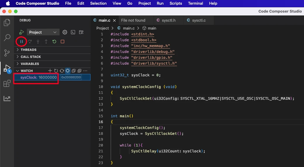
With this configuration, the system will be clocked directly from the MAIN Oscillator (External crystal) of 16MHz. Since there is no PLL used, the system clock will also be set at 16MHz.
Writing the main function
Inside the main function we will first configure the system clock and then retrieve the clock to confirm it. The main function is implemented below.
uint32_t sysClock = 0;
int main()
{
systemClockConfig();
sysClock = SysCtlClockGet();
while (1){
SysCtlDelay(sysClock);
}
}In this code, the systemClockConfig() function is first called to configure the microcontroller’s system clock. After the clock is set up, SysCtlClockGet() is used to read the current system clock frequency and store it in the variable sysClock. This value represents the MCU’s running frequency in hertz and can be used to calculate delays or verify clock settings.
Inside the infinite while loop, SysCtlDelay(sysClock) creates a delay based on the system clock value. This delay part is just added because without making some use of the sysClock value, it is not being evaluated in the watch expression. We will cover the Delays in the next tutorial.
By using sysClock in a watch expression during debugging, you can confirm that the system clock has been configured correctly.
Verifying the system Clock
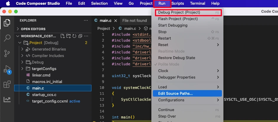
After building the project, launch the debugger by clicking the Run → Debug Project. This is shown in the image below.
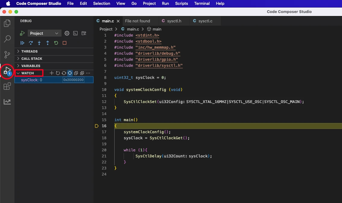
After the debugger is launched, add the sysClock in the Watch Expression as shown in the image below.
Next, Run the debugger and you will see the sysClock showing the current system clock.
As you can see in the image above, the sysClock shows 16MHz. This is correct since we are providing the clock from 16MHz external crystal, directly without using any PLL.
Precision Internal Oscillator (PIOSC)
The TM4C123G also provides an internal precision oscillator, which allows the MCU to run without any external crystal or resonator. This internal 16 MHz oscillator is always available on-chip, making it useful for quick prototyping, cost-sensitive designs, or applications where clock accuracy is not critical.
Unlike the main oscillator, the internal oscillator eliminates the need for external components, which reduces board complexity and power consumption. However, because it is less accurate and more sensitive to temperature and voltage variations, it may not be suitable for precise timing requirements such as UART baud rates or real-time clock operations.
In this section, we will configure the system clock to run directly from the internal oscillator without enabling the PLL, so the MCU will operate at its default internal frequency of 16 MHz.
The image below shows the clock diagram for TM4C123G and how the system will be clocked directly from the Internal Oscillator.
Include the required files
We will start with the necessary inclusions in the main.c file.
#include <stdint.h>
#include <stdbool.h>
#include "inc/hw_memmap.h"
#include "driverlib/debug.h"
#include "driverlib/gpio.h"
#include "driverlib/sysctl.h"
These inclusions serves the following purposes:
<stdint.h>and<stdbool.h>→ provide standard integer types (uint32_t) andbool."inc/hw_memmap.h"→ contains base addresses for all peripherals (like GPIO ports)."driverlib/debug.h"→ enables debug/error handling support."driverlib/gpio.h"→ functions for configuring and controlling GPIO pins."driverlib/sysctl.h"→ system control functions (clock, power, enabling peripherals).
Configure system Clock
void SysCtlClockSet(uint32_t ui32Config); is the TivaWare function to configure the system clock. The ui32Config parameter is a combination of macros that define:
- Desired system divider.
- The clock source (main oscillator, internal oscillator).
- Whether PLL is used or bypassed.
We will write a new function to configure the system clock. In this particular section, we will run the system directly from the main 16 MHz oscillator. I am creating the function systemClockConfig to configure the clock.
void systemClockConfig (void)
{
SysCtlClockSet(SYSCTL_OSC_INT|SYSCTL_USE_OSC);
}Inside the function systemClockConfig we will call SysCtlClockSet to set the desired clock for the system. The parameters used in this function are as follows:
SYSCTL_OSC_INTSelects the Internal oscillator as the clock source. The Internal Oscillator of 16MHz is selected by default.SYSCTL_USE_OSCTells the MCU to use the oscillator directly as the system clock without the PLL. Essentially, the clock comes straight from the crystal, so no frequency multiplication happens.
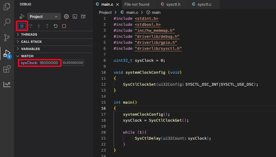
With this configuration, the system will be clocked directly from the Internal Oscillator of 16MHz. Since there is no PLL used, the system clock will also be set at 16MHz.
Writing the main function
Inside the main function we will first configure the system clock and then retrieve the clock to confirm it. The main function is implemented below.
uint32_t sysClock = 0;
int main()
{
    systemClockConfig();
    sysClock = SysCtlClockGet();

    while (1){
         SysCtlDelay(sysClock);
    }
}In this code, the systemClockConfig() function is first called to configure the microcontroller’s system clock. After the clock is set up, SysCtlClockGet() is used to read the current system clock frequency and store it in the variable sysClock. This value represents the MCU’s running frequency in hertz and can be used to calculate delays or verify clock settings.
Inside the infinite while loop, SysCtlDelay(sysClock) creates a delay based on the system clock value. This delay part is just added because without making some use of the sysClock value, it is not being evaluated in the watch expression. We will cover the Delays in the next tutorial.
By using sysClock in a watch expression during debugging, you can confirm that the system clock has been configured correctly.
Verifying the system Clock
After building the project, launch the debugger by clicking the Run → Debug Project. This is shown in the image below.
After the debugger is launched, add the sysClock in the Watch Expression as shown in the image below.
Next, Run the debugger and you will see the sysClock showing the current system clock.
As you can see in the image above, the sysClock shows 16MHz. This is correct since we are providing the clock from 16MHz Precision Internal Oscillator (PIOSC), directly without using any PLL.
Using the PLL for the Clock
So far, we have configured the system to run directly from either the external crystal (Main Oscillator) or the Precision Internal Oscillator (PIOSC). While both provide a 16 MHz system clock, many applications require higher clock speeds for faster processing and precise peripheral timing.
This is where the Phase-Locked Loop (PLL) comes in.
The PLL is a frequency multiplier circuit inside the TM4C123G that takes a stable reference clock (typically the 16 MHz main oscillator) and multiplies it up to a much higher frequency. Internally, the PLL produces a 400 MHz clock, which is then divided down by selectable dividers to provide the desired system clock.
Important: Although the PLL generates 400 MHz, the TM4C123 microcontroller limits the maximum system clock to 80 MHz. Any divider configuration that would result in a higher frequency is automatically capped by the hardware.
For example:
- With a 16 MHz crystal and PLL enabled, using
SYSCTL_SYSDIV_2_5gives 400 ÷ 2.5 = 160 MHz. Since this exceeds the device limit, the system clock is capped at 80 MHz, which is the maximum supported frequency of the TM4C123.
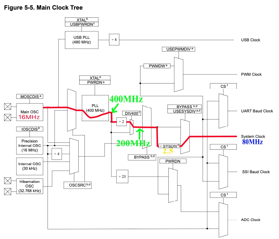
We will see an example where we will use the Main Oscillator (MOSC) with PLL to run the system at maximum 80MHz Clock. The image below shows the clock diagram for TM4C123G and how the system will be clocked from External Oscillator using PLL to reach 80MHz clock.
Include the required files
We will start with the necessary inclusions in the main.c file.
#include <stdint.h>
#include <stdbool.h>
#include "inc/hw_memmap.h"
#include "driverlib/debug.h"
#include "driverlib/gpio.h"
#include "driverlib/sysctl.h"These inclusions serves the following purposes:
<stdint.h>and<stdbool.h>→ provide standard integer types (uint32_t) andbool."inc/hw_memmap.h"→ contains base addresses for all peripherals (like GPIO ports)."driverlib/debug.h"→ enables debug/error handling support."driverlib/gpio.h"→ functions for configuring and controlling GPIO pins."driverlib/sysctl.h"→ system control functions (clock, power, enabling peripherals).
Configure system Clock
void SysCtlClockSet(uint32_t ui32Config); is the TivaWare function to configure the system clock. The ui32Config parameter is a combination of macros that define:
- Desired system divider.
- The clock source (main oscillator, internal oscillator).
- Whether PLL is used or bypassed.
We will write a new function to configure the system clock. In this particular section, we will run the system from the main 16 MHz oscillator and using the PLL, the frequency will be ramped up to 80MHz. I am creating the function systemClockConfig to configure the clock.
void systemClockConfig (void)
{
SysCtlClockSet(SYSCTL_OSC_MAIN|SYSCTL_USE_PLL|SYSCTL_XTAL_16MHZ|SYSCTL_SYSDIV_2_5);
}Inside the function systemClockConfig we will call SysCtlClockSet to set the desired clock for the system. The parameters used in this function are as follows:
SYSCTL_OSC_MAIN→ Selects the main oscillator (external crystal) as the clock source.SYSCTL_USE_PLL→ Enables the PLL so that the clock is multiplied internally (400 MHz → divided down).SYSCTL_XTAL_16MHZ→ Informs the MCU that the external crystal frequency is 16 MHz.SYSCTL_SYSDIV_2_5→ Sets the system clock divider to 2.5. After PLL output (200 MHz), dividing by 2.5 gives 80 MHz.
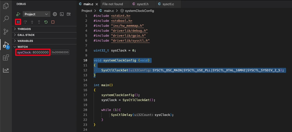
With this configuration, the system will be clocked using the PLL and the system clock will reach 80MHz.
System Clock Flow (16 MHz Crystal → 80 MHz System Clock)
- External Crystal (Main Oscillator)
- Frequency: 16 MHz
- This is the onboard crystal connected to the TM4C123 LaunchPad.
- PLL (Phase-Locked Loop)
- The 16 MHz reference from the main oscillator is multiplied internally by the PLL to produce 400 MHz.
- DIV400 Block
- The 400 MHz PLL output is divided by 2, resulting in 200 MHz.
- System Divider (
SYSCTL_SYSDIV_2_5)- The 200 MHz is further divided by 2.5, giving 80 MHz.
- System Clock Output
- The MCU runs at 80 MHz, which is the maximum supported frequency for the TM4C123.
- All core peripherals, timers, and SysTick will use this clock unless specifically configured otherwise.
Here’s a table of common SYSCTL_SYSDIV values for the TM4C123 when using a 16 MHz external crystal with PLL enabled:
SYSCTL_SYSDIV | PLL Output after DIV400 | System Clock (MHz) |
|---|---|---|
| 2.5 | 200 MHz | 80 |
| 3 | 200 MHz | 66.67 |
| 4 | 200 MHz | 50 |
| 5 | 200 MHz | 40 |
| 6 | 200 MHz | 33.33 |
| 8 | 200 MHz | 25 |
| 10 | 200 MHz | 20 |
| 20 | 200 MHz | 10 |
Notes:
- The PLL internally multiplies the 16 MHz crystal to 400 MHz.
- DIV400 always divides the PLL output by 2 → 200 MHz base for system divider.
- System clock = 200 ÷
SYSCTL_SYSDIV. - Maximum system clock is 80 MHz, even if the math allows higher.
Writing the main function
Inside the main function we will first configure the system clock and then retrieve the clock to confirm it. The main function is implemented below.
uint32_t sysClock = 0;
int main()
{
    systemClockConfig();
    sysClock = SysCtlClockGet();

    while (1){
         SysCtlDelay(sysClock);
    }
}
In this code, the systemClockConfig() function is first called to configure the microcontroller’s system clock. After the clock is set up, SysCtlClockGet() is used to read the current system clock frequency and store it in the variable sysClock. This value represents the MCU’s running frequency in hertz and can be used to calculate delays or verify clock settings.
Inside the infinite while loop, SysCtlDelay(sysClock) creates a delay based on the system clock value. This delay part is just added because without making some use of the sysClock value, it is not being evaluated in the watch expression. We will cover the Delays in the next tutorial.
By using sysClock in a watch expression during debugging, you can confirm that the system clock has been configured correctly.
Verifying the system Clock
After building the project, launch the debugger by clicking the Run → Debug Project. This is shown in the image below.
After the debugger is launched, add the sysClock in the Watch Expression as shown in the image below.
Next, Run the debugger and you will see the sysClock showing the current system clock.
As you can see in the image above, the sysClock shows 80MHz. This is correct since we are providing the clock from 16MHz external crystal and using PLL to increase it to 80MHz.
Conclusion
In this tutorial, we explored how to configure the TM4C123G system clock using TivaWare, covering:
- Main Oscillator – external 16 MHz crystal for precise timing.
- Internal Oscillator – convenient for prototypes, no external components needed.
- PLL – boosts the clock up to the maximum 80 MHz for high-performance operation.
We also showed how to use SysCtlClockSet() and verify the system clock with SysCtlClockGet(). Proper clock configuration is essential for optimizing speed, accuracy, and power consumption, enabling your MCU to perform reliably in any application.
In the next tutorial, we’ll dive deeper and implement precise delays, so you can control the LED timing more accurately and explore other timing-dependent applications.
Browse More TM4C123G Tutorials
TM4C123G Delay Tutorial – Using SysCtlDelay and SysTick Timer
TM4C123 GPIO Tutorial – Digital Input and Output using Tiva C LaunchPad
TM4C123 GPIO External Interrupts (Using TivaWare in Code Composer Studio)
TM4C123G UART Tutorial (PART 1) – How to Use UART and Virtual COM Port in Tiva C
TM4C123G UART Tutorial (PART 2): Use Interrupt to Receive Data and Control LEDs
I2C in TM4C123G Tiva C – How to Use I2C Peripheral with TivaWare
SPI Communication in TM4C123G: A Simple Guide
TM4C123G Clock Setup Project Download
Info
You can help with the development by DONATING Below.
To download the project, click the DOWNLOAD button.
TM4C123G Clock Setup FAQs
Yes, the TM4C123 supports using the internal oscillator as a PLL source, but it’s less common because the internal oscillator is less accurate than an external crystal. Timing-sensitive applications (UART, PWM, timers) may experience slight drift.
If the calculated system clock exceeds 80 MHz, the MCU automatically caps the frequency at 80 MHz. TivaWare ensures the system doesn’t run beyond the hardware limit.
Many peripheral modules (UART, timers, PWM, ADC) derive their clock from the system clock. Changing the system clock directly affects their timing, so you may need to adjust dividers or baud rates when changing the system clock frequency.
Yes, the TM4C123 allows switching between internal, external, and PLL clocks during runtime. However, care must be taken to ensure peripherals are reconfigured if timing changes, and the switch is done safely to avoid glitches.
SysCtlClockGet() only show frequency and not the clock source?SysCtlClockGet() calculates the system clock frequency from register values. It does not indicate whether the source is the internal oscillator, external crystal, or PLL, because the output frequency may be the same for multiple sources (e.g., 16 MHz from internal vs. 16 MHz from external crystal).

