Home ▸ Arduino ▸ Core Tutorials ▸
Updated On: May 29, 2026
Arduino UART Tutorial: Serial Communication with Practical Examples
UART (Universal Asynchronous Receiver-Transmitter) is the communication protocol Arduino uses to talk to your PC, GPS modules, GSM modules, Wi-Fi chips, and other microcontrollers. It is the protocol behind the Serial Monitor in the Arduino IDE.
In this guide, you will learn:
- How UART works and what parameters control it
- Which pins handle TX and RX on different Arduino boards
- How to send data from Arduino to your PC
- How to receive data from your PC and act on it
- How to control an LED over UART using commands from the Serial Monitor
- Common UART problems and how to fix them
This is part of the Arduino Core Tutorials series. Related tutorials:
- analogRead() and ADC
- digitalWrite() and digitalRead()
- PWM and analogWrite()
- delayMicroseconds()
- External interrupts
What is UART?
UART (Universal Asynchronous Receiver/Transmitter) is one of the most common ways for Arduino boards to communicate with other devices. It allows data to be sent and received one bit at a time over just two wires: TX (transmit) and RX (receive). Unlike parallel communication, where multiple bits are sent simultaneously, UART is simple, lightweight, and perfect for connecting Arduino to a computer, sensors, or other microcontrollers.
A UART frame diagram shows how data is transmitted bit by bit over a serial line between devices. Each frame consists of several key parts that ensure the data is sent and received correctly:
- Idle Line – When no data is being transmitted, the line remains at a logic HIGH (
1). This is the default state. - Start Bit – A single logic LOW (
0) signals the beginning of a data frame. The receiver detects this to know that incoming bits are about to arrive. - Data Bits – Typically 8 bits, sent least significant bit (LSB) first. These bits carry the actual information. Each bit lasts for the duration defined by the baud rate.
- Parity Bit (Optional) – Used for error checking. Depending on the configuration, it can be even or odd parity. If not used, this bit is skipped.
- Stop Bit(s) – One or more logic HIGH (
1) bits mark the end of the frame, allowing the receiver to prepare for the next data frame.
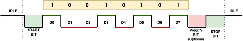
By looking at the UART frame diagram, you can visualise the sequence of bits on the TX/RX line. This makes it easier to understand how serial communication works, troubleshoot errors, and design communication protocols between Arduino and other devices.
UART Communication Parameters
UART uses a set of parameters that both devices must agree on before they can exchange data. If either side is configured differently, the data will be garbled or lost.
Baud rate defines how fast data is transmitted, measured in bits per second (bps). Both the Arduino and the connected device must use the same baud rate. Common values are 9600 and 115200. You set this in Arduino with Serial.begin(9600).
Data bits define how many bits make up one character. The standard is 8 bits.
Stop bits mark the end of each data packet. Arduino uses 1 stop bit by default.
Parity is an optional error-checking method. Arduino uses no parity by default.
Flow control manages the pace of data transfer to prevent buffer overflow. Standard Arduino boards do not use hardware flow control (RTS/CTS).
In Arduino, Serial.begin() handles all of these automatically using the most common defaults: 8 data bits, 1 stop bit, no parity.
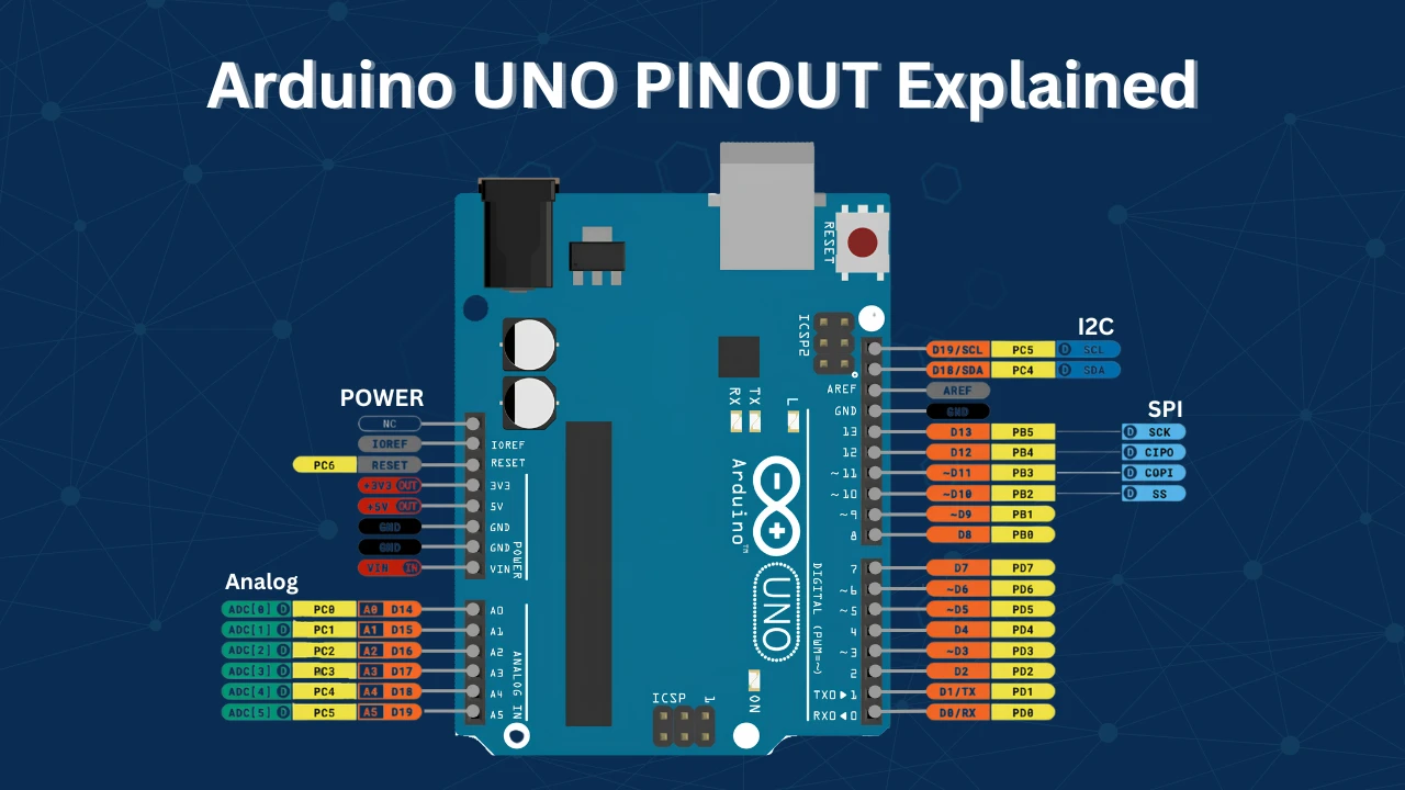
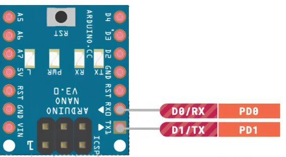
Arduino UART TX and RX Pins
UART communication uses two pins — TX (Transmit) and RX (Receive). TX sends data out; RX receives data in. When connecting two devices, TX on one side connects to RX on the other.
| Board | UART Port | TX Pin | RX Pin |
|---|---|---|---|
| Arduino UNO / Nano | Serial | 1 | 0 |
| Arduino Mega | Serial0 | 1 | 0 |
| Arduino Mega | Serial1 | 18 | 19 |
| Arduino Mega | Serial2 | 16 | 17 |
| Arduino Mega | Serial3 | 14 | 15 |
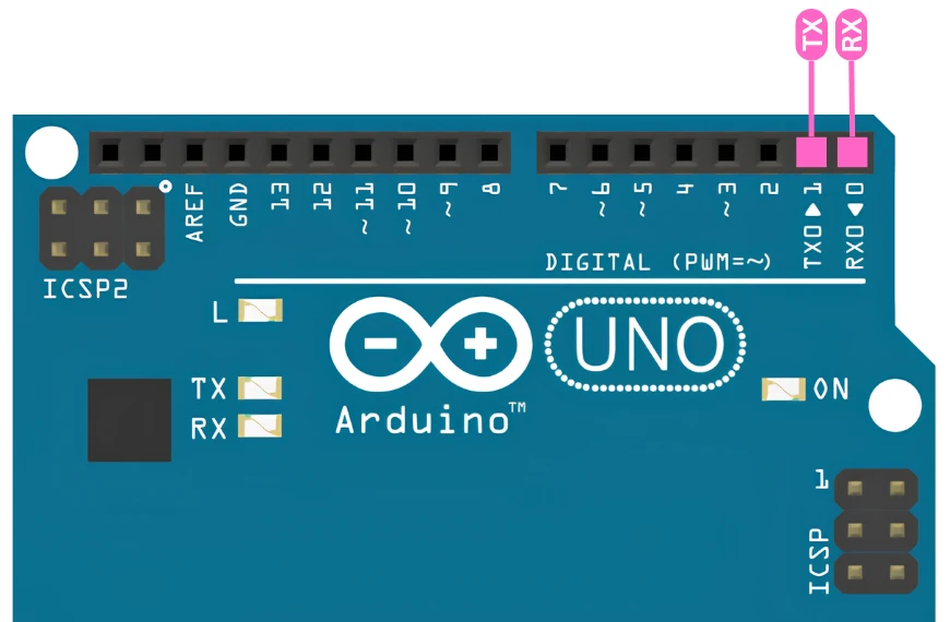
Note for UNO and Nano:
Pins 0 and 1 are shared with the USB interface. Avoid connecting other devices to these pins while using the USB connection to your PC — it will cause conflicts and may prevent uploading sketches.
Connecting Arduino to PC via UART
Most Arduino boards (UNO, Nano, Mega) have a built-in USB-to-Serial converter. Connecting the USB cable to your PC is all you need to use the Serial Monitor in the Arduino IDE.
If you need to use the hardware UART pins directly — for example, when the USB port is occupied by another device — you can use an external USB-to-TTL converter such as the FT232.
Wiring for USB-to-TTL converter:
- Arduino TX → FT232 RX
- Arduino RX → FT232 TX
- Arduino GND → FT232 GND
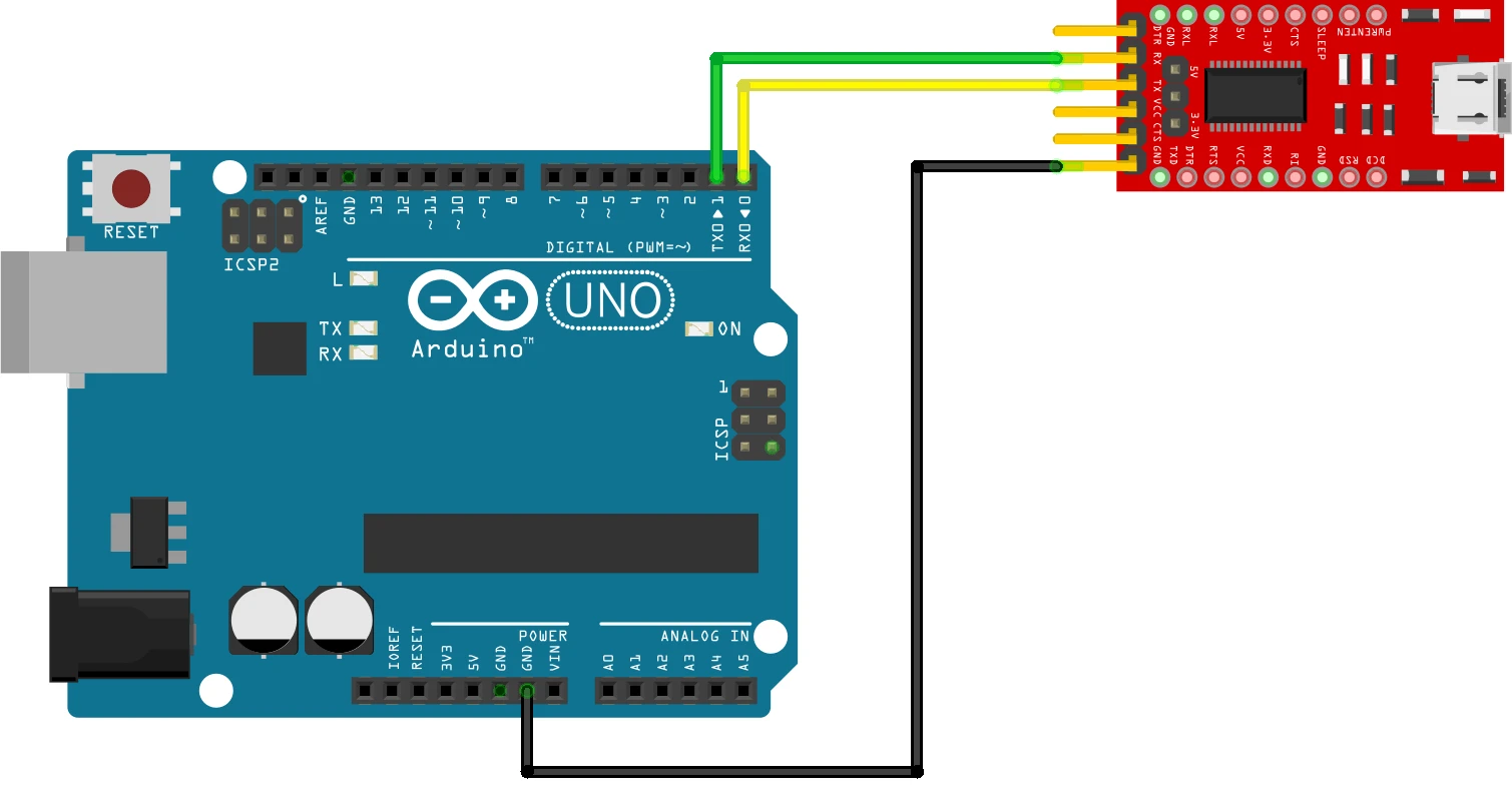
Always cross the TX and RX lines. TX of one device connects to RX of the other — never TX to TX.
Sending Data from Arduino to PC
The most common use of UART is sending data from Arduino to the Serial Monitor — for sensor readings, debug messages, or status updates.
Code
void setup() {
  Serial.begin(9600);  // Initialize UART at 9600 baud
}

void loop() {
  Serial.println("Hello, PC!");  // Send a message to the PC
  delay(1000);                   // Wait 1 second before the next message
}Serial.begin(9600) initialises UART communication at 9600 bits per second. Serial.println() sends the text followed by a newline character, so each message appears on its own line in the Serial Monitor.
The delay(1000) keeps messages readable — without it, the monitor would flood with data.
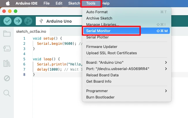
Viewing Output in Serial Monitor
- Upload the code to your Arduino.
- Open the Arduino IDE.
- Go to Tools → Serial Monitor (or press
Ctrl+Shift+M). - Set the baud rate in the Serial Monitor to 9600 — it must match
Serial.begin().
Once the Arduino is running the above code:
- Open the Arduino IDE.
- Go to Tools → Serial Monitor (or press
Ctrl+Shift+M).
- Set the baud rate in the Serial Monitor to match your
Serial.begin()(e.g., 9600). - You will see “Hello, PC!” appearing every second.
The GIF below shows the output of the above code on the Serial monitor.
This simple example demonstrates one-way UART communication from Arduino to your PC. It’s useful for debugging, logging sensor data, or sending status messages to your computer.
Receiving Data from PC
Arduino can also receive data from the PC over UART. This is useful for sending commands, updating variables, or controlling hardware in real time from the Serial Monitor.
When the PC sends data, it arrives one byte at a time on the RX pin and is stored in a buffer. You check if data is available with Serial.available(), then read it with Serial.read().
Echo Example — Read and Send Back
void setup() {
  Serial.begin(9600);
  Serial.println("Send me a message:");
}

void loop() {
  if (Serial.available() > 0) {          // Check if data is waiting in the buffer
    char receivedChar = Serial.read();   // Read one byte
    Serial.print("You sent: ");
    Serial.println(receivedChar);        // Echo it back to the PC
  }
}Serial.available() returns the number of bytes waiting to be read. If it is greater than 0, data has arrived. Serial.read() reads one byte from the buffer. The character is then echoed back so you can confirm the Arduino received it correctly.
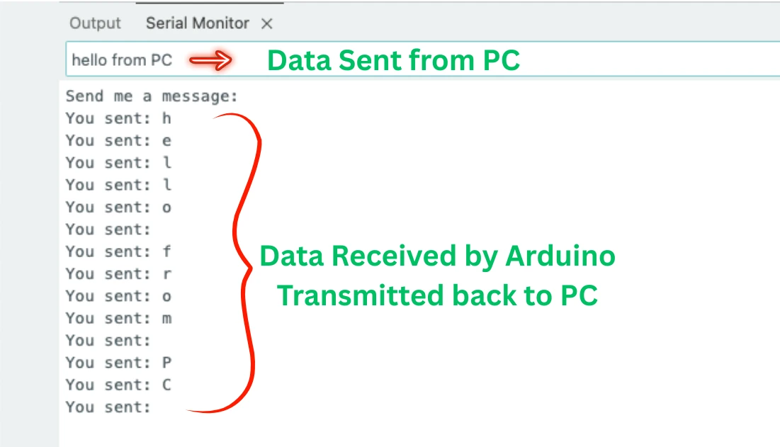
Both devices must use the same baud rate. If they do not match, the received data will appear as random characters.
Controlling an LED via UART Commands
You can use UART to control hardware from your PC. This example turns an LED on pin 13 ON when it receives 1 and OFF when it receives 0.
Code
const int LED_PIN = 13;

void setup() {
  Serial.begin(9600);
  pinMode(LED_PIN, OUTPUT);
  Serial.println("Send 1 to turn the LED ON.");
  Serial.println("Send 0 to turn the LED OFF.");
}

void loop() {
  if (Serial.available() > 0) {
    char receivedChar = Serial.read();

    if (receivedChar == '1') {
      digitalWrite(LED_PIN, HIGH);
      Serial.println("LED turned ON");
    } else if (receivedChar == '0') {
      digitalWrite(LED_PIN, LOW);
      Serial.println("LED turned OFF");
    }
  }
}The Arduino waits for incoming data. When it receives the character '1', it sets pin 13 HIGH and prints a confirmation. When it receives '0', it sets pin 13 LOW. Any other character is ignored — the LED state does not change.
Note that the incoming data is compared as a character ('1'), not an integer (1). The Serial Monitor sends ASCII characters, so the character '1' has a value of 49, not 1.
Output
The GIF below shows the LED is controlled by the data received from PC via UART.

As you can see in the GIF, when a ‘1’ is sent by the PC, the LED is turned ON. Similarly, when a ‘0’ is sent, the LED is turned OFF. When any other data is sent (other than ‘0’ and ‘1’), the LED is not affected at all.
Arduino Serial Library Functions
| Function | Description |
|---|---|
Serial.begin(baudRate) | Initializes UART at the specified baud rate |
Serial.print(data) | Sends data without a trailing newline |
Serial.println(data) | Sends data followed by a newline |
Serial.available() | Returns the number of bytes waiting in the RX buffer |
Serial.read() | Reads and removes one byte from the RX buffer |
Serial.readString() | Reads the full incoming string until a timeout |
Serial.flush() | Waits until all outgoing data has been transmitted |
Common UART Problems and Fixes
Garbled or Unreadable Data
Cause: Baud rate mismatch between the Arduino and the receiving device.
Fix: Make sure Serial.begin() in your sketch matches the baud rate set in the Serial Monitor. If you change the baud rate in your code, close and reopen the Serial Monitor and update its baud rate setting.
No Data Received
Cause: TX and RX pins are wired incorrectly, or the USB connection is conflicting with hardware pins.
Fix:
- Always cross TX and RX — Arduino TX goes to the other device’s RX.
- Always connect GND between both devices. Without a common ground, UART will not work reliably.
- On UNO and Nano, avoid using pins 0 and 1 for external devices when the USB cable is connected.
Data Received Only Partially
Cause: Reading data too fast before the full message has arrived in the buffer.
Fix: Use Serial.available() to wait until enough bytes have arrived, or use Serial.readString() which waits for a timeout before returning the full string.
Hardware UART vs SoftwareSerial
The Arduino UNO has one hardware UART (pins 0 and 1). If you need a second UART port — for example, to talk to a GPS module while still using the Serial Monitor — you can use the SoftwareSerial library to simulate UART on any two digital pins.
SoftwareSerial is slower and less reliable at high baud rates. Use hardware UART whenever possible, and reserve SoftwareSerial for secondary peripherals at lower baud rates (9600 or below).
#include <SoftwareSerial.h>

SoftwareSerial gpsSerial(4, 5);  // RX = pin 4, TX = pin 5

void setup() {
  Serial.begin(9600);      // Hardware UART → Serial Monitor
  gpsSerial.begin(9600);   // SoftwareSerial → GPS module
}Arduino UART: Frequently Asked Questions
Conclusion
UART is the foundational communication protocol in the Arduino ecosystem — it is how your sketch talks to your PC during development, how your board connects to GPS, GSM, Wi-Fi, and Bluetooth modules in deployed projects, and how two microcontrollers exchange data in larger systems. The Serial library abstracts all the hardware complexity: Serial.begin() configures the baud rate, Serial.available() tells you when data has arrived, and Serial.read() retrieves it one byte at a time.
In this tutorial you covered the full one-wire-per-direction model — TX out, RX in, GND shared — and the four parameters that both sides must agree on before a single byte transfers correctly. You sent data to the PC with Serial.println(), received it back with Serial.read(), parsed command characters to control an LED, and confirmed the behaviour live in the Serial Monitor.
The troubleshooting section covers the three problems that catch nearly every beginner: baud rate mismatch producing garbled output, TX/RX crossed the wrong way producing silence, and using SoftwareSerial on a Uno when hardware UART pins are already occupied by USB.
UART feeds naturally into more advanced protocols. I2C connects multiple sensors on two wires with addressed communication. SPI gives you higher-speed full-duplex transfers for displays and SD cards. External interrupts let your board react to a UART RX event without polling Serial.available() in every loop iteration. Download the full project above and explore the Arduino Core tutorials collection for the next step.
Download Arduino UART Serial Communication Project Files
Complete Arduino sketches for UART serial communication: transmit "Hello, PC!" every second via Serial.println(), receive and echo characters with Serial.read(), and control the onboard LED on pin 13 by sending '1' (ON) and '0' (OFF) from the Serial Monitor. All code runs at 9600 baud and is compatible with Uno, Nano, and Mega. Free to download — support the work if it helped you.
Browse More Arduino Core Tutorials
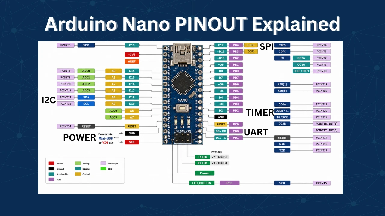
Arduino Nano Pinout – Complete Guide with Diagram
Arduino digitalWrite() and digitalRead(): Complete Guide with Examples
Arduino ADC and analogRead() Explained: Complete Guide with Examples
Arduino I2C Tutorial: Wire Library, Master/Slave, Scanner & Troubleshooting
Arduino delayMicroseconds() Tutorial: Precise Timing, Pulses & Alternatives

Subscribe
Login
0 Comments
Newest
