Published: November 6, 2025
Last Updated: February 6, 2026
Last Updated: February 6, 2026
UART in TM4C123G Tiva C – Use UART and Virtual COM Port
UART (Universal Asynchronous Receiver Transmitter) is one of the most common ways to communicate between microcontrollers and external devices like sensors, GPS modules, or PCs. The TM4C123G Tiva C LaunchPad comes with multiple UART modules that make serial communication fast and reliable.
In this tutorial, we’ll explore everything about UART in TM4C123G — how many UART modules it has, which pins are used, and how UART is different from USART. We’ll also look at how UART compares to SPI and I2C, and how the Virtual COM Port (VCP) helps you connect the board directly to your computer via USB.
By the end of this post, you’ll understand how UART works in Tiva C and how to use it for your embedded projects.
Recommended Resources:
I have already covered how to create a project in CCStduio and configure system clock in the previous tutorials. This tutorial is going to be a continuation in this series, so you must read the following tutorials first:
- How to Setup CCStudio and build your first project with TM4C123G
- How to configure system clock in TM4C123G
Introduction to UART in TM4C123G
What is UART Communication?
UART stands for Universal Asynchronous Receiver Transmitter. It is a simple and reliable serial communication protocol used to send and receive data between two devices.
In UART, data is transmitted bit by bit over a single wire, without any clock signal. That’s why it’s called asynchronous. Both devices must agree on the same baud rate (data speed) before communication begins — for example, 9600 bps or 115200 bps.
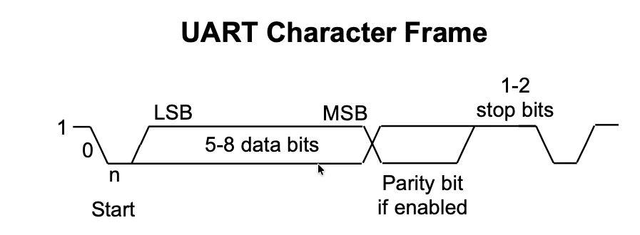
A UART frame usually includes a start bit, 8 data bits, an optional parity bit, and one or more stop bits. This structure makes UART very easy to implement and debug.
UART is commonly used for:
- Debugging and logging data from a microcontroller
- Communicating with sensors or GPS modules
- Sending serial data to a PC through a COM port
Why UART is Important in Microcontrollers
Almost every microcontroller supports UART because it’s the simplest way to establish serial communication. It doesn’t need complex wiring or timing management.
With UART, you can:
- Monitor variables or sensor data through a serial terminal.
- Send commands from your computer to control a device.
- Connect wireless modules like Bluetooth HC-05 or GSM SIM800 easily.
Since UART uses only two main pins — TX (Transmit) and RX (Receive). It saves GPIO pins and keeps your design clean.
For debugging, UART is a life-saver. You can print messages or variable values directly to a serial terminal, making it easier to track program flow or find errors in your code.
Overview of UART Support in TM4C123G
The TM4C123G Tiva C LaunchPad from Texas Instruments comes with 8 UART modules, named UART0 to UART7.
Each UART module can work independently and supports:
- Full-duplex communication (simultaneous transmit and receive)
- Baud rates up to 5 Mbps
- FIFO buffers for smooth data handling
- Hardware flow control (CTS/RTS) on some modules
These UARTs are very flexible, each module can be mapped to multiple pins using alternate pin functions. This gives you freedom to use UART alongside other peripherals depending on your project needs.
The UART0 module is special. It is connected internally to the onboard USB interface through a Virtual COM Port (VCP). This means you can connect your LaunchPad to your PC using a simple USB cable and use UART0 for serial communication directly — no external USB-to-Serial converter is needed.
We’ll learn more about this Virtual COM Port later in this tutorial.
UART vs SPI vs I2C – Which One to Choose?
Serial communication in microcontrollers can be done in many ways, and the most common ones are UART, SPI, and I2C. Each protocol has its own strengths, weaknesses, and ideal use cases. Let’s look at how they compare and when you should prefer UART over the others.
Comparison of Communication Speed
| Protocol | Typical Speed | Max Speed (approx.) | Clock Signal |
|---|---|---|---|
| UART | 9600 bps – 115200 bps | up to ~5 Mbps | No |
| SPI | 1 Mbps – 10 Mbps | up to 50 Mbps or more | Yes |
| I2C | 100 kbps (Standard), 400 kbps (Fast), 3.4 Mbps (High-Speed) | up to 5 Mbps | Yes |
- SPI is generally the fastest because it uses a dedicated clock line and separate data lines for transmit and receive.
- UART is slower but doesn’t need a shared clock, which simplifies wiring.
- I2C is designed for short-range communication between chips on the same board, and it’s slower but very efficient for multiple devices.
For most debugging or sensor data applications, UART’s 115200 bps is more than enough.
Number of Wires and Complexity
| Protocol | Wires Needed | Type of Communication | Complexity |
|---|---|---|---|
| UART | 2 wires (TX, RX) | Point-to-Point | Simple |
| SPI | 4 + N (MOSI, MISO, SCK, CS + extra per device) | Master-Slave | Moderate |
| I2C | 2 wires (SCL, SDA) | Multi-Master, Multi-Slave | High |
- UART is the easiest to set up — just two wires and both devices agree on a baud rate.
- SPI uses separate lines for sending and receiving data, and each slave needs its own chip-select pin.
- I2C is efficient with wiring (only two lines for all devices) but requires addressing and timing management, which makes the software side a bit more complex.
If you want a simple one-to-one link between MCU and PC, UART is the cleanest choice.
For multiple fast peripherals like sensors or displays, SPI is better.
For many slow devices (e.g., RTC, EEPROM, sensors), I2C works well.
When to Use UART Instead of SPI or I2C
Use UART when:
- You need communication between the MCU and a computer (e.g., debugging or logging via USB-to-Serial).
- You want to connect to modules like Bluetooth (HC-05), GPS, or GSM, which all use UART interfaces.
- You prefer simple wiring and reliable asynchronous data exchange without needing a shared clock.
- You only need one device on the communication line.
SPI when:
- You need high-speed data transfer, such as with displays or memory chips.
- Timing precision is important and both devices are on the same board.
Use I2C when:
- You want to connect multiple low-speed devices using only two wires.
- You can tolerate slower communication and more complex software.
Summary
| Feature | UART | SPI | I2C |
|---|---|---|---|
| Speed | Medium | Very Fast | Moderate |
| Wires | 2 | 4 + | 2 |
| Devices | 1 to 1 | 1 to many | 1 to many |
| Clock | No | Yes | Yes |
| Ease of Use | Very Easy | Moderate | Complex |
For simple, reliable, and easy communication, especially with the PC via Virtual COM Port, UART is the best choice on the TM4C123G LaunchPad.
UART Modules Available in TM4C123G
How Many UART Modules are Available
The TM4C123G microcontroller comes with a total of 8 UART modules, named UART0 to UART7. Each module can be used for asynchronous serial communication, and all of them support full-duplex operation, meaning they can transmit and receive data simultaneously.
These modules are independent of each other, so you can use one UART to communicate with a PC while another connects to a Bluetooth or GPS module at the same time.
Here’s a quick summary:
- UART0 → connected to the USB interface (Virtual COM Port)
- UART1–UART7 → available for external communication via GPIO pins
Each UART supports:
- Baud rates up to 5 Mbps
- 16-byte transmit and receive FIFOs
- Optional hardware flow control (RTS and CTS signals)
- Parity and stop bit configuration for flexible data framing
This makes UART communication in TM4C123G both powerful and easy to use.
UART Base Addresses and Peripheral Names
Each UART module in TM4C123G has a unique base address and peripheral name defined in the TivaWare library. You’ll need these when configuring UART registers directly or when enabling UART modules in your code.
| UART Module | Peripheral Name | Base Address (Hex) |
|---|---|---|
| UART0 | SYSCTL_PERIPH_UART0 | 0x4000C000 |
| UART1 | SYSCTL_PERIPH_UART1 | 0x4000D000 |
| UART2 | SYSCTL_PERIPH_UART2 | 0x4000E000 |
| UART3 | SYSCTL_PERIPH_UART3 | 0x4000F000 |
| UART4 | SYSCTL_PERIPH_UART4 | 0x40010000 |
| UART5 | SYSCTL_PERIPH_UART5 | 0x40011000 |
| UART6 | SYSCTL_PERIPH_UART6 | 0x40012000 |
| UART7 | SYSCTL_PERIPH_UART7 | 0x40013000 |
Note: You usually won’t need to use these base addresses directly unless you’re working at register level.
If you’re using TivaWare APIs, you can simply use the peripheral name like UART0_BASE or SYSCTL_PERIPH_UART0.
UART Pin Configuration and Alternate Functions
Each UART module can be mapped to multiple GPIO pins depending on your board layout and available peripherals. The TM4C123G uses alternate pin functions — meaning a single pin can serve multiple roles (for example, GPIO, UART, or SSI).
Here are the default pin mappings for each UART module:
| UART | TX Pin | RX Pin | Port |
|---|---|---|---|
| UART0 | PA1 | PA0 | Port A |
| UART1 | PB1 | PB0 | Port B |
| UART2 | PD7 | PD6 | Port D |
| UART3 | PC7 | PC6 | Port C |
| UART4 | PC5 | PC4 | Port C |
| UART5 | PE5 | PE4 | Port E |
| UART6 | PD5 | PD4 | Port D |
| UART7 | PE1 | PE0 | Port E |
Note: Some pins (like PD7) are locked by default and must be unlocked using the GPIO Lock and Commit registers before using them for UART.
You can remap pins using GPIOPinConfigure() with the proper alternate function.
For example:
GPIOPinConfigure(GPIO_PA0_U0RX);
GPIOPinConfigure(GPIO_PA1_U0TX);
GPIOPinTypeUART(GPIO_PORTA_BASE, GPIO_PIN_0 | GPIO_PIN_1);This allows you to assign UART functionality to the correct pins easily.
Setting Up UART in Code Composer Studio (CCS) for TM4C123G
Before we start sending or receiving data over UART, we first need to set up the UART peripheral in Code Composer Studio (CCS).
This section will guide you through creating a new project, adding the TivaWare driver library, and writing the basic code to configure UART0 for serial communication through the Virtual COM Port (VCP).
Creating a New CCS Project for Tiva C LaunchPad
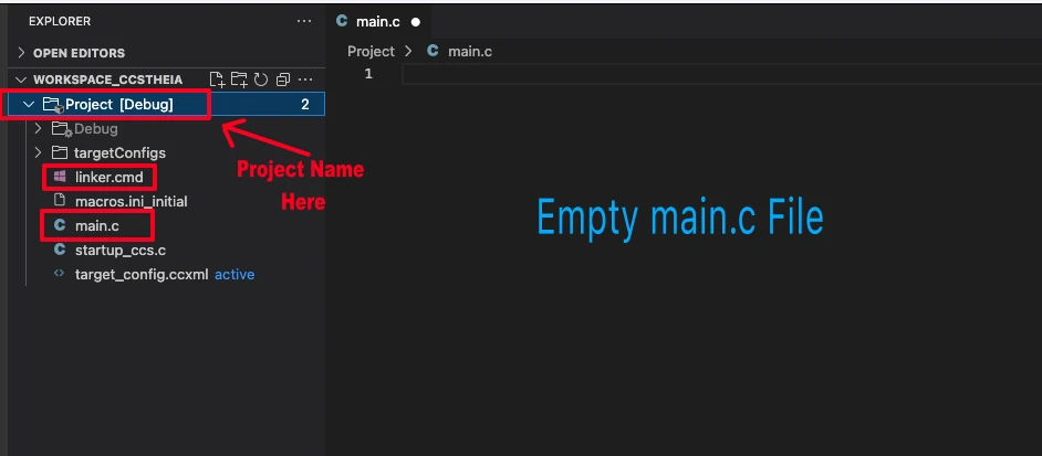
I have already explained how to create a new project in TM4C123 using CCStudio. You can create a similar project with blinky template and then modify it for this tutorial.
There are only 2 things we need to do to turn the blinky template into a new project:
- Delete everything from the blinky.c file, so it should be completely empty. We will write everything ourselves.
- Rename the following:
- blinky.c → main.c, indicating that this is the main file for the project
- blinky_css.cmd → linker.cmd, indicating that this is the linker file
- blinky (Folder) → projectName (Folder)
The final modified project is shown in the image below.
Including TivaWare Driver Library
To simplify UART configuration, we’ll use the TivaWare driver library, which provides ready-to-use APIs for enabling peripherals and setting up UART communication.
Include the following header files at the top of your program:
#include <stdint.h>
#include <stdbool.h>
#include "inc/hw_memmap.h"
#include "driverlib/sysctl.h"
#include "driverlib/gpio.h"
#include "driverlib/uart.h"
#include "driverlib/pin_map.h"These headers serve the following purpose:
| Header File | Purpose | Example Function |
|---|---|---|
| driverlib/sysctl.h | Controls system clock and peripheral power | SysCtlPeripheralEnable() |
| driverlib/gpio.h | Configures GPIO pins for alternate functions | GPIOPinTypeUART() |
| driverlib/uart.h | Manages UART configuration and data transfer | UARTConfigSetExpClk() |
| driverlib/pin_map.h | Maps GPIO pins to their UART functions | GPIOPinConfigure() |
| inc/hw_memmap.h | Defines base addresses of peripherals | UART0_BASE, GPIO_PORTA_BASE |
Enabling UART Modules in TivaWare
Before using any UART module, you must enable its clock in the System Control (SYSCTL) module. This ensures that the peripheral is powered and ready for configuration.
Here’s how to enable and configure UART0 using TivaWare APIs:
void UART0_Init(void)
{
// Enable UART0 and Port A
SysCtlPeripheralEnable(SYSCTL_PERIPH_UART0);
SysCtlPeripheralEnable(SYSCTL_PERIPH_GPIOA);
// Wait for peripherals to be ready
while(!SysCtlPeripheralReady(SYSCTL_PERIPH_UART0));
while(!SysCtlPeripheralReady(SYSCTL_PERIPH_GPIOA));
// Configure pins for UART0 (PA0=RX, PA1=TX)
GPIOPinConfigure(GPIO_PA0_U0RX);
GPIOPinConfigure(GPIO_PA1_U0TX);
GPIOPinTypeUART(GPIO_PORTA_BASE, GPIO_PIN_0 | GPIO_PIN_1);
// Configure UART clock and baud rate
UARTClockSourceSet(UART0_BASE, UART_CLOCK_PIOSC);
UARTConfigSetExpClk(UART0_BASE, 16000000, 115200,
(UART_CONFIG_WLEN_8 | UART_CONFIG_STOP_ONE | UART_CONFIG_PAR_NONE));
// Enable UART
UARTEnable(UART0_BASE);
}This function UART0_Init() initializes UART0 on the TM4C123G microcontroller for serial communication (TX/RX). It sets up the required peripherals, pins, and UART configuration so you can send and receive data through the USB (Virtual COM Port).
Line-by-Line Explanation
SysCtlPeripheralEnable(SYSCTL_PERIPH_UART0);
SysCtlPeripheralEnable(SYSCTL_PERIPH_GPIOA);Enables the clock for UART0 and GPIO Port A, since UART0 pins (PA0 and PA1) belong to Port A. Without enabling the clock, the peripherals won’t function.
while(!SysCtlPeripheralReady(SYSCTL_PERIPH_UART0));
while(!SysCtlPeripheralReady(SYSCTL_PERIPH_GPIOA));Waits until both peripherals are ready to use. This ensures the hardware is fully powered before configuration.
GPIOPinConfigure(GPIO_PA0_U0RX);
GPIOPinConfigure(GPIO_PA1_U0TX);
GPIOPinTypeUART(GPIO_PORTA_BASE, GPIO_PIN_0 | GPIO_PIN_1);Configures the pins PA0 and PA1 for UART RX and TX using their alternate functions. This assigns UART0’s receive and transmit functions to those pins.
UARTClockSourceSet(UART0_BASE, UART_CLOCK_PIOSC);Selects the Precision Internal Oscillator (PIOSC) as the clock source for UART0. This is a 16 MHz internal clock, independent of the system clock.
Each UART module in the TM4C123G can use different clock sources. By default, the system uses the 16 MHz internal oscillator (PIOSC), but you can also choose the system clock. The clock source is important because the UART baud rate is calculated based on it.
For example, if you select PIOSC as the clock (UARTClockSourceSet(UART0_BASE, UART_CLOCK_PIOSC)) and configure the baud rate as 115200, the UART timing will be correct. However, if the UART module uses a different clock (like a PLL-based system clock) without adjusting the baud rate calculation, you may see garbled characters on the serial terminal.
UARTConfigSetExpClk(UART0_BASE, 16000000, 115200,
(UART_CONFIG_WLEN_8 | UART_CONFIG_STOP_ONE | UART_CONFIG_PAR_NONE));This sets the UART communication format. It configures the UART for:
- Baud rate: 115200
- Data length: 8 bits
- Stop bits: 1
- Parity: None
UARTEnable(UART0_BASE);Finally, enables UART0 so it can start transmitting and receiving data.
Virtual COM Port (VCP) in TM4C123G
What is a Virtual COM Port
A Virtual COM Port (VCP) allows your computer to communicate with a microcontroller through USB, but it appears as a normal serial port (COMx) to the operating system.
This means you can use any serial terminal software (like PuTTY, Tera Term, or Arduino Serial Monitor) to send and receive data, just like using a hardware UART port, even though the connection actually happens over USB.
In short, VCP bridges USB and UART, making it easy to exchange serial data between your PC and the microcontroller without any extra USB-to-Serial converter.
How VCP Works in TM4C123G LaunchPad
The TM4C123G Tiva C LaunchPad includes an onboard ICDI (In-Circuit Debug Interface) chip from Texas Instruments.
This chip performs two main functions:
- It allows programming and debugging the MCU through the USB cable.
- It also provides a Virtual COM Port that connects directly to the MCU’s UART0 module.
So when you plug the LaunchPad into your computer using the micro-USB cable, the ICDI chip presents two interfaces:
- One for debugging/programming (JTAG)
- One for UART communication (VCP)
This means you can open a serial terminal on your PC, connect to the VCP, and exchange data with UART0 — all through the same USB cable you use for flashing your code.
Note: No extra hardware (like a USB-to-UART converter module) is needed. The board’s built-in ICDI chip handles it automatically.
Using UART0 for USB Communication
The UART0 module of TM4C123G is internally connected to the ICDI chip. Its pins PA0 (U0RX) and PA1 (U0TX) are hardwired to the VCP interface.
When you initialize UART0 (as we did earlier using UART0_Init()), any data you transmit with UARTCharPut() will appear as serial output on your computer’s virtual COM port.
For example:
UARTCharPut(UART0_BASE, 'A');Will print the character ‘A’ to the serial console on the computer.
Similarly, data you type into the terminal on your PC will be received by the MCU through:
UARTCharGet(UART0_BASE);So effectively, UART0 acts as a USB serial interface between your code and your PC terminal.
How to View Serial Output on a PC
Once you program your LaunchPad and connect it via USB, the PC automatically detects the Virtual COM Port. You can use any serial terminal software like Putty, Realterm, etc. or WCHSerialPort on mac.
You need to configure your serial terminal software with the same communication settings as the UART0 configuration in your code.
For example:
Baud rate: 115200
Data bits: 8
Parity: None
Stop bits: 1
Flow control: None
These settings must match exactly on both sides — the TM4C123G and your PC terminal — for the data to be transmitted and displayed correctly.
The image below shows the serial port configured on WCHSerialPort in Mac.

Example Code for UART Communication in TM4C123G
Sending Data to the Virtual COM Port
In this part, we’ll learn how to send strings, numbers, and floating-point values from the TM4C123G microcontroller to the Virtual COM Port (VCP) using UART0.
All transmitted data can be viewed on a serial terminal such as PuTTY or Tera Term.
How to Send a String through UART0
You can send a string by transmitting each character one by one using UARTCharPut().
void UART0_SendString(const char *str)
{
    while(*str)
    {
        UARTCharPut(UART0_BASE, *str++);
    }
}Example usage:
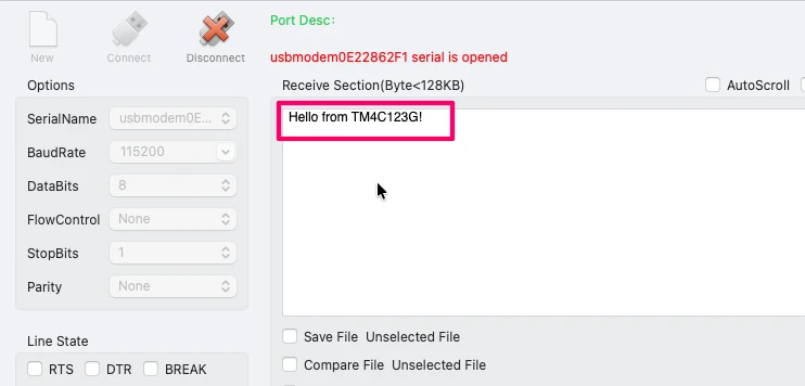
UART0_SendString("Hello from TM4C123G!\r\n");This will display the message on your PC’s serial terminal. This is shown in the image below.
How to Send an Integer through UART0
To send an integer, you must first convert it into a string, because UART transmits only character data.
#include <stdio.h>

void UART0_SendInt(int num)
{
    char buffer[12];
    sprintf(buffer, "%d", num);    // convert integer to string
    UART0_SendString(buffer);
    UART0_SendString("\r\n");
}Example usage:
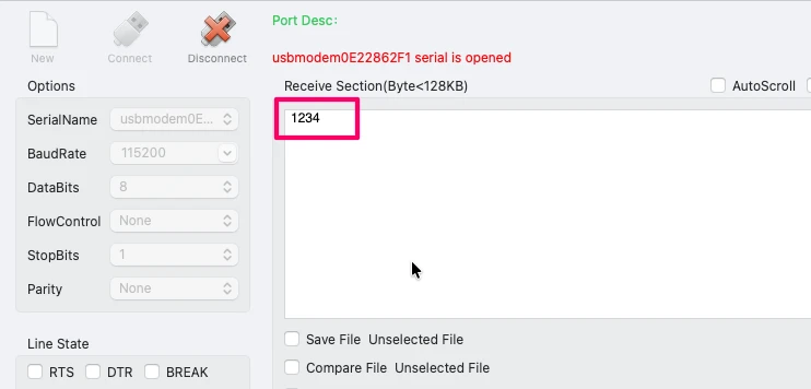
UART0_SendInt(1234);This will print the number on your PC’s serial terminal. This is shown in the image below.
How to Send a Floating-Point Number
Just like integers, you can send floats after converting them to a string.
void UART0_SendFloat(float num)
{
    char buffer[20];
    sprintf(buffer, "%.2f", num);   // 2 decimal places
    UART0_SendString(buffer);
    UART0_SendString("\r\n");
}Example usage:
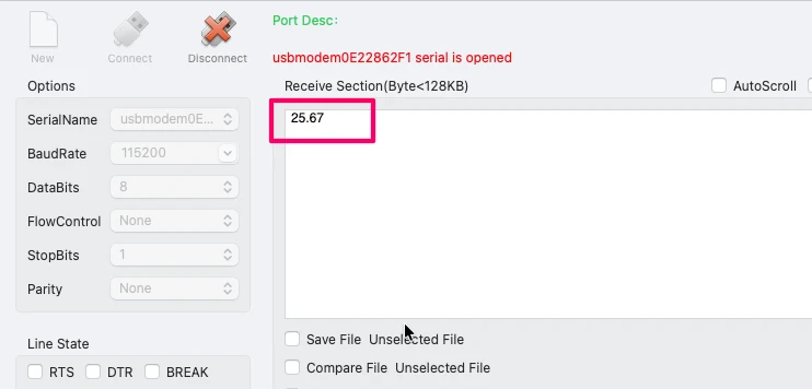
UART0_SendFloat(25.67);This will print the float value on your PC’s serial terminal. This is shown in the image below.
Receiving Data from the Virtual COM Port
Once the UART0 is initialized and running, we can easily receive characters sent from the PC over the Virtual COM Port (VCP). Each time you type a key in the serial terminal (for example PuTTY or Tera Term), the character travels through the USB cable to the MCU’s UART0 RX (PA0) pin.
The code below shows a simple example that checks if a character is available, reads it, and immediately sends it back to the PC.
if (UARTCharsAvail(UART0_BASE))              // Check if any data is available
{
    char c = UARTCharGet(UART0_BASE);   // Read one character from UART
    UARTCharPut(UART0_BASE, c);                    // Echo the same character back
}How It Works:
UARTCharsAvail(UART0_BASE)
This function checks the UART receive FIFO.- It returns true if at least one byte of data has been received.
- It returns false if the receive buffer is empty.
UARTCharGet(UART0_BASE)
Reads the received character from the UART data register. This function will wait until the data is received from UART.UARTCharPut(UART0_BASE, c)
Sends the same character back through UART0 TX (PA1).
On your PC terminal, whatever you type will be echoed back immediately.
Complete Example Loop:
You can place the above code inside your main loop:
while (1)
{
    if (UARTCharsAvail(UART0_BASE))
    {
        char c = UARTCharGet(UART0_BASE);
        UARTCharPut(UART0_BASE, c);
    }
}Now open your serial terminal (115200 baud, 8-N-1, no flow control), type any characters, and you’ll see them appear instantly on the screen — confirming that your TM4C123G is correctly receiving and processing UART data.
You can see this in the video below.
Conclusion
In this tutorial, we learned everything about UART communication in the TM4C123G Tiva C LaunchPad — from understanding what UART is, how many UART modules are available, and how it differs from USART, SPI, and I2C.
We explored how to set up UART0 for communication through the Virtual COM Port (VCP), and how to send and receive data between the microcontroller and the PC.
You also saw practical examples for transmitting strings, integers, and floating-point numbers, and how to read incoming data efficiently using TivaWare APIs.
UART is one of the most important and beginner-friendly communication protocols in embedded systems.
With the TM4C123G’s built-in UART modules and Virtual COM Port support, you can easily debug your programs, display sensor data, or even build command-based control interfaces from your PC.
Once you understand UART, you can apply the same logic to communicate with other serial devices like Bluetooth, GSM, or GPS modules.
Browse More TM4C123G Tutorials
TM4C123G Clock Setup Tutorial – Configure System Clock with PLL
TM4C123G Delay Tutorial – Using SysCtlDelay and SysTick Timer
TM4C123 GPIO Tutorial – Digital Input and Output using Tiva C LaunchPad
TM4C123 GPIO External Interrupts (Using TivaWare in Code Composer Studio)
TM4C123G UART Tutorial (PART 2): Use Interrupt to Receive Data and Control LEDs

I2C in TM4C123G Tiva C – How to Use I2C Peripheral with TivaWare
SPI Communication in TM4C123G: A Simple Guide
TM4C123G UART Project Download
TM4C123G UART FAQs
Subscribe
Login
0 Comments
Newest
