
Published: October 21, 2025
Last Updated: February 6, 2026
Last Updated: February 6, 2026
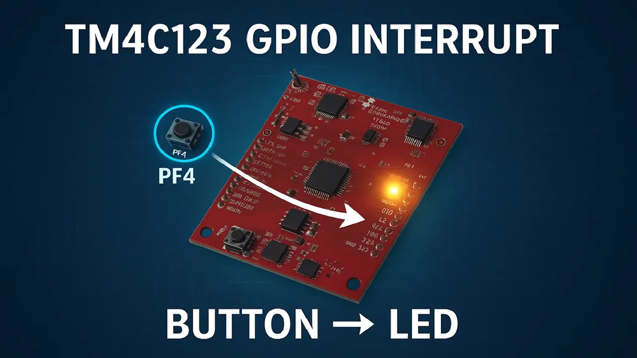
TM4C123 GPIO External Interrupt Tutorial (Using Code Composer Studio)
In this tutorial, we’ll learn how to use external interrupts with GPIO pins on the TM4C123 Tiva C LaunchPad.
Instead of constantly checking the button (polling), we let the microcontroller respond automatically whenever the button is pressed using hardware interrupts.
This approach is efficient and ideal for real-time applications.
Recommended Resources:
I have already covered how to create a project in CCStduio, configure system clock and GPIO in the previous tutorials. This tutorial is going to be a continuation in this series, so you must read the following tutorials first:
- How to Setup CCStudio and build your first project with TM4C123G
- How to configure system clock in TM4C123G
- How to configure GPIO in TM4C123G
Understanding GPIO Interrupts in TM4C123
How GPIO Interrupts Work
GPIO interrupts in the TM4C123 Tiva C microcontroller allow the processor to respond instantly to external events, such as a button press or sensor signal. Instead of continuously checking a pin’s logic level inside a loop, you can configure the MCU to automatically react when a specific condition occurs — for example, when a signal changes from HIGH to LOW.
When this happens, the processor temporarily pauses its main program and executes a special function known as the Interrupt Service Routine (ISR). Inside the ISR, you can define what the microcontroller should do in response — such as turning on an LED, updating a variable, or reading sensor data.
After completing the ISR, the MCU resumes its normal operation. This makes the system faster, more efficient, and responsive, especially when handling time-sensitive inputs.
Interrupt Trigger Types
The TM4C123 supports several types of GPIO interrupt triggers, allowing flexible response configurations based on your application’s needs:
- Falling Edge – Triggered when the signal transitions from HIGH to LOW. This is the most common mode for push buttons, which connects using pull-up resistors.
- Rising Edge – Triggered when the signal goes from LOW to HIGH.
- Both Edges – Triggers whenever the signal changes state, whether rising or falling.
- Level-Sensitive (High or Low Level) – Keeps the interrupt active as long as the pin remains HIGH or LOW.
You can select the trigger type using the GPIOIntTypeSet() function in TivaWare, giving you complete control over how the interrupt responds to input signals.
Edge vs Level Triggered Interrupts (Comparison)
The two main interrupt modes: edge-triggered and level-triggered. They behave differently and are used in different situations.
| Feature | Edge-Triggered | Level-Triggered |
|---|---|---|
| Trigger Condition | Activates on signal transition (LOW→HIGH or HIGH→LOW) | Activates when signal stays HIGH or LOW |
| Common Use Case | Buttons, switches, or pulse signals | External devices that hold a line HIGH/LOW until serviced |
| Re-triggering | Occurs only once per edge | Remains active as long as the level condition exists |
| Response Speed | Faster for quick changes | Suitable for stable, continuous signals |
| Debouncing Need | Often required | Usually not critical |
Edge-triggered interrupts are ideal for momentary signals, like button presses, while level-triggered interrupts work well when a signal stays constant until acknowledged.
Benefits of Using GPIO Interrupts in Embedded Systems
Using GPIO interrupts offers multiple advantages over traditional polling methods:
- Efficient CPU usage: The microcontroller remains idle or runs other tasks until an event occurs.
- Faster response time: Interrupts are handled immediately, ensuring quick reactions to external signals.
- Lower power consumption: The MCU can stay in low-power mode and wake only when needed.
- Simpler code structure: You can separate event-handling logic into clean, dedicated ISRs.
- Scalability: Multiple inputs can be managed easily without increasing CPU load.
GPIO interrupts make embedded systems faster, smarter, and more power-efficient. That’s why real-world applications use them extensively for sensor detection, user interfaces, and communication protocols.
Setting Up GPIO Interrupts in Code Composer Studio (CCS)
Before writing the interrupt code, you need to properly set up your project and configure the required peripherals. The following steps will guide you through creating a new project in Code Composer Studio (CCS) and preparing the environment to use GPIO interrupts on the TM4C123 Tiva C LaunchPad.
Creating a New CCS Project for Tiva C LaunchPad
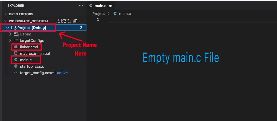
I have already explained how to create a new project in TM4C123 using CCStudio. You can create a similar project with blinky template and then modify it for this tutorial.
There are only 2 things we need to do to turn the blinky template into a new project:
- Delete everything from the blinky.c file, so it should be completely empty. We will write everything ourselves.
- Rename the following:
- blinky.c → main.c, indicating that this is the main file for the project
- blinky_css.cmd → linker.cmd, indicating that this is the linker file
- blinky (Folder) → projectName (Folder)
The final modified project is shown in the image below.
Including Required Header Files
Before using any TivaWare functions, you need to include the essential header files in your main.c. These headers provide access to system control, GPIO, interrupt management, and memory-mapped registers.
#include <stdint.h>
#include <stdbool.h>
#include "inc/hw_memmap.h"
#include "driverlib/sysctl.h"
#include "driverlib/gpio.h"
#include "driverlib/interrupt.h"Here’s what each file does:
- hw_memmap.h – Defines base addresses for all peripherals like GPIO, UART, and timers.
- hw_ints.h – Contains interrupt vector definitions for different modules.
- sysctl.h – Handles clock configuration, peripheral control, and power management.
- gpio.h – Provides functions for GPIO pin setup and interrupt configuration.
- interrupt.h – Enables global interrupt control and vector table registration.
These headers together allow you to manage GPIO pins, set interrupt conditions, and control the system clock — all using clean and readable function calls.
Enabling Peripheral and Configuring Pin
After including the headers, the next step is to enable the GPIO peripheral and configure the pins you’ll use.
In this tutorial, we’ll use Port F —
- PF4 will act as the input pin (connected to the onboard switch SW1).
- PF1 will be used as the output pin (connected to the red LED).
Start by enabling the GPIO port and waiting until it’s ready:
SysCtlPeripheralEnable(SYSCTL_PERIPH_GPIOF);
while(!SysCtlPeripheralReady(SYSCTL_PERIPH_GPIOF));At this point, your GPIO pins are properly configured, and the system is ready for interrupt setup in the next section.
Writing Code for GPIO Interrupt
After configuring the GPIO pins, we set up the interrupt on the input pin. Here, we configure PF4 as an input with a pull-up resistor, PF1 as an output LED, and link PF4 to trigger an interrupt when the button is pressed.
Each part of the configuration is explained clearly below.
Configure GPIO Input with Pull-Up
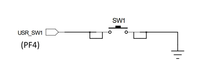
To use PF4 (SW1 button) as an interrupt source, it must first be configured as a digital input. Since the onboard button pulls the pin LOW when pressed, we need an internal pull-up resistor to keep it HIGH by default.
GPIOPinTypeGPIOInput(GPIO_PORTF_BASE, GPIO_PIN_4);
GPIOPadConfigSet(GPIO_PORTF_BASE, GPIO_PIN_4, GPIO_STRENGTH_2MA, GPIO_PIN_TYPE_STD_WPU);Here:
GPIOPinTypeGPIOInput()sets PF4 as an input pin.GPIOPadConfigSet()enables a 2mA drive strength and activates the internal weak pull-up resistor (WPU), ensuring the pin stays HIGH when not pressed.
When the button is pressed, PF4 goes LOW — creating a falling edge, which we’ll use to trigger the interrupt.
Configure GPIO Output (LED)
Next, configure PF1 (the red LED) as an output pin. This LED will turn ON or OFF inside the interrupt routine whenever the button is pressed.
GPIOPinTypeGPIOOutput(GPIO_PORTF_BASE, GPIO_PIN_1);This single line sets PF1 as a digital output. You can control it using GPIOPinWrite() inside your ISR or main code.
Setup GPIO Interrupt Trigger
Now, let’s configure the interrupt behavior for the input pin.
We’ll use a falling edge trigger, since PF4 transitions from HIGH to LOW when the button is pressed.
GPIOIntDisable(GPIO_PORTF_BASE, GPIO_PIN_4); // Disable interrupt during setup
GPIOIntClear(GPIO_PORTF_BASE, GPIO_PIN_4); // Clear any pending interrupts
GPIOIntTypeSet(GPIO_PORTF_BASE, GPIO_PIN_4, GPIO_FALLING_EDGE); // Falling edge trigger
GPIOIntEnable(GPIO_PORTF_BASE, GPIO_PIN_4); // Enable interrupt for PF4Explanation:
GPIOIntDisable()ensures no interrupts occur while configuring.GPIOIntClear()removes any previous interrupt flag.GPIOIntTypeSet()defines the trigger condition (falling edge).GPIOIntEnable()re-enables interrupts on PF4.
This setup ensures the interrupt only triggers when the user presses the button.
Register ISR and Enable Global Interrupts
Once the interrupt type is configured, the next step is to register the Interrupt Service Routine (ISR) and enable global interrupt handling.
GPIOIntRegister(GPIO_PORTF_BASE, GPIOF_Handler); // Register ISR for Port F
IntEnable(INT_GPIOF); // Enable GPIOF interrupt in NVIC
IntMasterEnable(); // Enable global interruptsHere:
GPIOIntRegister()tells the microcontroller which function (ISR) to call when a Port F interrupt occurs. Here it is callingGPIOF_Handler().IntEnable()enables the GPIOF interrupt in the Nested Vector Interrupt Controller (NVIC).IntMasterEnable()globally enables interrupt handling across the system.
At this point, your system is fully set up to respond to GPIO events.
Define the Interrupt Service Routine (ISR)
Instead of performing a delay or toggling the LED directly inside the ISR, we’ll set a flag to indicate that the button was pressed. The main loop will check this flag and perform the LED toggle safely.
volatile bool buttonPressed = false;
void GPIOF_Handler(void)
{
GPIOIntClear(GPIO_PORTF_BASE, GPIO_PIN_4); // Clear interrupt flag
buttonPressed = true; // Set flag to notify main loop
}By now, the interrupt system is fully configured. Each time the button on PF4 is pressed, the microcontroller instantly jumps to the ISR and set the flag buttonPressed to true.
Complete Example Code
This is the full working code where PF4 button presses change the state of the LED on PF1. Each press turns the LED ON if it was OFF, and OFF if it was ON.
#include <stdint.h>
#include <stdbool.h>
#include "inc/hw_memmap.h"
#include "driverlib/sysctl.h"
#include "driverlib/gpio.h"
#include "driverlib/systick.h"
#include "driverlib/interrupt.h"
// System clock configuration
void systemClockConfig(void)
{
SysCtlClockSet(SYSCTL_XTAL_16MHZ | SYSCTL_USE_PLL | SYSCTL_OSC_MAIN | SYSCTL_SYSDIV_2_5);
}
// SysTick for delay
volatile uint32_t msTicks = 0;
void SysTick_Handler(void)
{
msTicks++;
}
void delay_ms(uint32_t ms)
{
uint32_t start = msTicks;
while ((msTicks - start) < ms) {}
}
void SysTick_Init(void)
{
SysTickPeriodSet(SysCtlClockGet() / 1000);
SysTickIntRegister(SysTick_Handler);
SysTickIntEnable();
SysTickEnable();
}
// Flag for button press
volatile bool buttonPressed = false;
void GPIOF_Handler(void)
{
GPIOIntClear(GPIO_PORTF_BASE, GPIO_PIN_4); // Clear interrupt flag
buttonPressed = true; // Set flag
}
int main(void)
{
systemClockConfig();
SysTick_Init();
// Enable GPIOF
SysCtlPeripheralEnable(SYSCTL_PERIPH_GPIOF);
while(!SysCtlPeripheralReady(SYSCTL_PERIPH_GPIOF));
// Configure pins
GPIOPinTypeGPIOInput(GPIO_PORTF_BASE, GPIO_PIN_4);
GPIOPadConfigSet(GPIO_PORTF_BASE, GPIO_PIN_4, GPIO_STRENGTH_2MA, GPIO_PIN_TYPE_STD_WPU);
GPIOPinTypeGPIOOutput(GPIO_PORTF_BASE, GPIO_PIN_1);
// Setup GPIO interrupt
GPIOIntDisable(GPIO_PORTF_BASE, GPIO_PIN_4);
GPIOIntClear(GPIO_PORTF_BASE, GPIO_PIN_4);
GPIOIntTypeSet(GPIO_PORTF_BASE, GPIO_PIN_4, GPIO_FALLING_EDGE);
GPIOIntRegister(GPIO_PORTF_BASE, GPIOF_Handler);
GPIOIntEnable(GPIO_PORTF_BASE, GPIO_PIN_4);
// Enable Master Interrupt
IntMasterEnable();
// Main loop
while(1)
{
static bool ledState = false;
if(buttonPressed)
{
ledState = !ledState; // Change LED state
GPIOPinWrite(GPIO_PORTF_BASE, GPIO_PIN_1, ledState ? GPIO_PIN_1 : 0);
delay_ms(500); // Prevent Debouncing
buttonPressed = false;
}
}
}Explanation
- System Clock and SysTick: Configures MCU clock to 80 MHz and sets up SysTick to create millisecond delays using
delay_ms(). - GPIO Input: PF4 is configured as input with an internal pull-up resistor.
- GPIO Output: PF1 controls the red LED.
- Interrupt Setup: The falling edge on PF4 triggers the ISR
GPIOF_Handler(), which only sets a flag. - IntMasterEnable(): Enables the master interrupt. This will enable both systick interrupt and GPIO interrupt.
- Flag Handling: The main loop checks
buttonPressed. When set, it changes the LED state instead of using a blocking delay inside the ISR. - LED State Change: Using
ledState = !ledStateallows the LED to toggle between ON and OFF with each button press, keeping the ISR fast and efficient.
Mechanical push buttons often generate multiple rapid signals when pressed or released. This is called bouncing, and it can cause the LED to toggle multiple times on a single press.
To handle this, we can implement a simple software debounce using a short delay in the main loop after detecting the button press. I have added a 500ms Delay to prevent it.
Output / Result of GPIO Interrupt
When you press the onboard SW1 button (PF4):
- The red LED (PF1) changes its state — turns ON if it was OFF, and OFF if it was ON.
- Each press is handled immediately via the GPIO interrupt, while the ISR remains non-blocking.
The gif below shows the working of this project.

As you can see above, when the button is pressed, the LED state changes. If the LED is OFF, it turns ON, and if it is ON, it turns OFF. The 500ms Delay we added prevents debouncing of the button.
Conclusion
In this tutorial, we explored how to use GPIO interrupts on the TM4C123 Tiva C LaunchPad to respond instantly to external events like button presses. By configuring PF4 as an input with an internal pull-up resistor and PF1 as an output for the LED, we created a system where each button press changes the LED state. We emphasized the importance of keeping the Interrupt Service Routine (ISR) fast and non-blocking by using a flag to signal events to the main loop. This approach ensures that the microcontroller remains responsive and can handle other tasks or interrupts without delay.
We also introduced software debouncing using a short delay in the main loop to prevent multiple triggers from a single button press, making the LED response consistent and reliable. Overall, this method demonstrates best practices for handling GPIO inputs efficiently, combining interrupts with a flag-based system to create robust, real-time embedded applications. By following these techniques, you can extend the same concepts to multiple buttons, sensors, or other external signals in more complex projects, maintaining both performance and reliability.
Browse More TM4C123G Tutorials
TM4C123G Clock Setup Tutorial – Configure System Clock with PLL
TM4C123G Delay Tutorial – Using SysCtlDelay and SysTick Timer
TM4C123 GPIO Tutorial – Digital Input and Output using Tiva C LaunchPad

TM4C123G UART Tutorial (PART 1) – How to Use UART and Virtual COM Port in Tiva C

TM4C123G UART Tutorial (PART 2): Use Interrupt to Receive Data and Control LEDs

I2C in TM4C123G Tiva C – How to Use I2C Peripheral with TivaWare
SPI Communication in TM4C123G: A Simple Guide
TM4C123G GPIO Interrupt Project Download
TM4C123G GPIO Interrupt FAQs
Subscribe
Login
0 Comments
Newest
