
Published: October 20, 2025
Last Updated: February 6, 2026
Last Updated: February 6, 2026
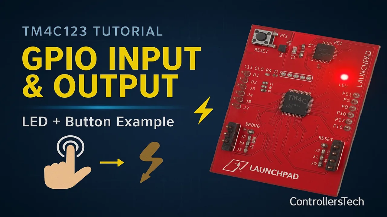
TM4C123 GPIO Tutorial – How to Use Digital Input and Output with Tiva C LaunchPad
The TM4C123 Tiva C LaunchPad is one of the best boards to start learning ARM Cortex-M programming. In this tutorial, we will learn how to use GPIO (General Purpose Input/Output) pins on the TM4C123 to control LEDs and read button inputs.
GPIO is the foundation of every embedded system. It allows the microcontroller to interact with the real world — turning LEDs ON or OFF, reading switches, or controlling sensors.
Before diving into advanced topics like UART, ADC, or PWM, it’s essential to understand how GPIO works.
We’ll use STM32CubeIDE with the TM4C123 microcontroller, and you’ll learn step by step how to:
- Configure GPIO pins as input or output
- Toggle LEDs using software
- Read button states and control LEDs accordingly
By the end of this tutorial, you’ll be comfortable with basic digital I/O operations on the Tiva C LaunchPad, and ready to move toward interrupts and timers.
Recommended Resources:
I have already covered how to create a project in CCStduio and configure system clock in the previous tutorials. This tutorial is going to be a continuation in this series, so you must read the following tutorials first:
- How to Setup CCStudio and build your first project with TM4C123G
- How to configure system clock in TM4C123G
Introduction to GPIO on TM4C123
What is GPIO in TM4C123?
GPIO stands for General Purpose Input/Output.
In the TM4C123 Tiva C microcontroller, GPIO pins are the basic interface between the microcontroller and the outside world. These pins can be configured as input or output, allowing the microcontroller to either read signals from sensors, switches, and buttons, or send signals to devices such as LEDs, motors, and relays.
The TM4C123 microcontroller comes with six GPIO ports — Port A to Port F — providing a total of 43 GPIO pins. Each port is 8 bits wide, meaning it can handle up to 8 pins, although some ports may have fewer usable pins depending on the device package.
These GPIO pins are highly flexible. You can:
- Configure each pin as digital input or output.
- Enable internal pull-up or pull-down resistors.
- Use alternate functions like UART, SPI, I2C, or PWM when needed.
- Control output levels directly from software using registers.
GPIO is the first step in understanding how the TM4C123 communicates with other hardware components. It lays the foundation for working with all other peripherals in the system.
Why Learn GPIO Before Other Peripherals?
Before learning complex peripherals like UART, ADC, or timers, it’s important to master GPIO programming. Here’s why:
- Fundamental for All Embedded Applications
GPIO operations form the base of every embedded project. Whether you’re blinking an LED, reading a button, or controlling a sensor, you’ll always use GPIO at some point. - Simple and Easy to Understand
Working with GPIO helps you get familiar with register-level programming, bit masking, and hardware-level control — concepts that are essential when dealing with any microcontroller peripheral. - Visual Feedback for Learning
Turning LEDs ON and OFF or reacting to a button press gives immediate feedback. This makes it much easier to debug your setup and understand how your code interacts with hardware. - Gateway to Advanced Features
Once you’re comfortable with GPIO, you’ll naturally be ready to explore interrupts, timers, and communication interfaces. All of these use similar concepts of configuration and control.
Understanding GPIO Ports and Pins on TM4C123
GPIO Port Names and Pin Count
The TM4C123 microcontroller includes multiple GPIO ports labeled from Port A to Port F. Each port typically contains 8 pins, named Px0 to Px7, where “x” represents the port letter.
However, not all pins are always available for general use — some are reserved for special functions like JTAG, NMI, or oscillator inputs. The exact number of usable GPIO pins depends on the specific TM4C123 variant and its package type.
Here’s a quick summary of the available GPIO ports on TM4C123:
| Port | Pin Range | Notes |
|---|---|---|
| Port A | PA0 – PA7 | Commonly used for UART and SPI functions |
| Port B | PB0 – PB7 | Supports I2C and PWM functions |
| Port C | PC0 – PC7 | Some pins are reserved for JTAG |
| Port D | PD0 – PD7 | Can be used for USB or GPIO functions |
| Port E | PE0 – PE5 | Fewer pins, often used for ADC inputs |
| Port F | PF0 – PF4 | Connected to onboard LEDs and switches |
Each port must have its clock enabled through the SYSCTL_RCGCGPIO register before you can use it. Once the clock is active, you can configure individual pins as input or output, and control their logic levels directly through GPIO registers.
How GPIO Pins are Connected to the Tiva C LaunchPad LEDs and Buttons
The Tiva C LaunchPad (TM4C123GXL) provides easy access to GPIO pins through headers and onboard components like LEDs and switches.
Here’s how the onboard peripherals are connected:
| Component | GPIO Pin | Port | Function |
|---|---|---|---|
| Red LED | PF1 | Port F | Digital Output |
| Blue LED | PF2 | Port F | Digital Output |
| Green LED | PF3 | Port F | Digital Output |
| Switch 1 (SW1) | PF4 | Port F | Digital Input (Active Low) |
| Switch 2 (SW2) | PF0 | Port F | Digital Input (Active Low) |
When you press a switch, it connects the pin to ground (logic LOW). Therefore, the default state of the switches is logic HIGH due to internal pull-up resistors.
This simple configuration makes it easy to test GPIO programming — you can toggle LEDs or read button presses without any external components.
Unlocking and Configuring Special GPIO Pins (like PF0)
Some GPIO pins on the TM4C123 are locked by default for safety and debugging purposes. One common example is PF0, which is used as a Non-Maskable Interrupt (NMI) pin.
To use PF0 as a normal GPIO pin, you need to unlock it in software before configuration. This is done using a specific sequence involving the GPIOLOCK and GPIOCR registers.
Here’s how to unlock PF0:
- Write the unlock key
0x4C4F434Bto the LOCK register of Port F. - Set the corresponding bit for PF0 in the COMMIT (CR) register to allow changes.
- Once unlocked, configure PF0 as an input or output pin using normal GPIO functions.
Example:
HWREG(GPIO_PORTF_BASE + GPIO_O_LOCK) = 0x4C4F434B;   // Unlock Port F
HWREG(GPIO_PORTF_BASE + GPIO_O_CR) |= 0x01; // Allow changes to PF0Once unlocked, you can set PF0 as input or output like any other GPIO pin.
This step is especially important when using the onboard SW2 button, since it’s connected to PF0.
By understanding which pins are locked, shared, or reserved, you can avoid conflicts and make full use of the TM4C123’s GPIO capabilities.
Setting Up GPIO in Code Composer Studio (CCS) for TM4C123
Before we start controlling LEDs or reading button inputs, we first need to set up GPIO in Code Composer Studio (CCS).
This section will guide you through creating a new project, adding the TivaWare library, and writing the basic code to enable and configure GPIO pins for the TM4C123 Tiva C LaunchPad.
Creating a New CCS Project for Tiva C LaunchPad
I have already explained how to create a new project in TM4C123 using CCStudio. You can create a similar project with blinky template and then modify it for this tutorial.
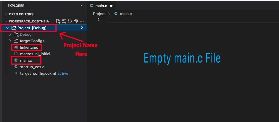
There are only 2 things we need to do to turn the blinky template into a new project:
- Delete everything from the blinky.c file, so it should be completely empty. We will write everything ourselves.
- Rename the following:
- blinky.c → main.c, indicating that this is the main file for the project
- blinky_css.cmd → linker.cmd, indicating that this is the linker file
- blinky (Folder) → projectName (Folder)
The final modified project is shown in the image below.
Including TivaWare Driver Library
To make programming easier, we’ll use TivaWare, which provides ready-to-use driver functions like GPIOPinTypeGPIOOutput() and SysCtlPeripheralEnable().
Include TivaWare headers in your program:
#include "driverlib/sysctl.h"
#include "driverlib/gpio.h"
#include "inc/hw_memmap.h"These headers serve the following purpose:
| Header File | Purpose | Example Function or Macro |
|---|---|---|
driverlib/sysctl.h | Controls system-level settings like clocks | SysCtlPeripheralEnable() |
driverlib/gpio.h | Configures and controls GPIO pins | GPIOPinWrite() |
inc/hw_memmap.h | Defines base addresses of peripherals | GPIO_PORTF_BASE |
Enabling GPIO Clock in Code
Every GPIO port in the TM4C123 requires a clock before it can be used.
This clock is controlled by the System Control module, and you can enable it using the TivaWare function SysCtlPeripheralEnable().
Example:
SysCtlPeripheralEnable(SYSCTL_PERIPH_GPIOF);   // Enable clock for Port F
while(!SysCtlPeripheralReady(SYSCTL_PERIPH_GPIOF)); // Wait until readyThis ensures that the GPIOF module is fully powered and ready to use before configuration.
Configuring Pins as Input or Output
Once the GPIO clock is enabled, you can configure the direction of each pin. Use TivaWare functions to set pins as input or output.
Example:
// Configure PF1, PF2, PF3 as output (LEDs)
GPIOPinTypeGPIOOutput(GPIO_PORTF_BASE, GPIO_PIN_1 | GPIO_PIN_2 | GPIO_PIN_3);
// Configure PF0 and PF4 as input (Switches)
GPIOPinTypeGPIOInput(GPIO_PORTF_BASE, GPIO_PIN_0 | GPIO_PIN_4);If you’re using the onboard push buttons, you should also enable internal pull-up resistors, since the switches are active LOW:
GPIOPadConfigSet(GPIO_PORTF_BASE, GPIO_PIN_0 | GPIO_PIN_4, GPIO_STRENGTH_2MA, GPIO_PIN_TYPE_STD_WPU);Now your GPIO pins are ready for digital input and output operations.
Writing Code for Digital Output (LED Control)
Controlling LEDs is the first step in learning how to use GPIO pins. With the TM4C123 Tiva C LaunchPad, you can easily turn LEDs on or off by writing to the appropriate GPIO pins.
Initialize GPIO Port and Direction
Before controlling LEDs, the corresponding GPIO port must be enabled, and the pins connected to LEDs must be configured as outputs.
In Code Composer Studio (CCS) with TivaWare, you can do this using the following steps:
- Enable the GPIO Port Clock
SysCtlPeripheralEnable(SYSCTL_PERIPH_GPIOF);   // Enable clock for Port F
while(!SysCtlPeripheralReady(SYSCTL_PERIPH_GPIOF)); // Wait until ready- Configure LED Pins as Output
The TM4C123 LaunchPad has onboard LEDs connected to PF1 (Red), PF2 (Blue), PF3 (Green).
GPIOPinTypeGPIOOutput(GPIO_PORTF_BASE, GPIO_PIN_1 | GPIO_PIN_2 | GPIO_PIN_3);Now the pins are ready to be driven HIGH or LOW.
Set or Clear Pin Output Value
Once a pin is configured as output, you can turn the LED on or off using the GPIOPinWrite() function.
- Turn ON an LED: Write the pin HIGH
GPIOPinWrite(GPIO_PORTF_BASE, GPIO_PIN_1, GPIO_PIN_1); // Turn ON Red LED- Turn OFF an LED: Write the pin LOW
GPIOPinWrite(GPIO_PORTF_BASE, GPIO_PIN_1, 0); // Turn OFF Red LEDYou can control multiple LEDs at the same time by OR-ing the pin masks in the function call.
GPIOPinWrite(GPIO_PORTF_BASE, GPIO_PIN_1|GPIO_PIN_2, GPIO_PIN_1|GPIO_PIN_2); // Turn ON LEdsExample Code to Blink LED using GPIO
Here’s a simple example that blinks the Red LED (PF1) continuously using a delay. The code combines system clock setup, GPIO output control, and a millisecond timer using SysTick interrupts to blink an LED reliably.
Using SysTick is preferred over simple delay loops because it allows accurate, interrupt-driven timing that won’t be affected by CPU speed changes. I have covered the usage of Delay in TM4C123G, you can check it out.
#include <stdint.h>
#include <stdbool.h>
#include "inc/hw_memmap.h"
#include "driverlib/gpio.h"
#include "driverlib/sysctl.h"
#include "driverlib/systick.h"
#include "driverlib/interrupt.h"   // for IntMasterEnable


// System Clock Related Functions
void systemClockConfig (void)
{
    // Using MOSC 16MHz (External) -> PLL (400MHz) -> PLL (200MHz)/2.5 = 80MHz
    SysCtlClockSet(SYSCTL_XTAL_16MHZ|SYSCTL_USE_PLL|SYSCTL_OSC_MAIN|SYSCTL_SYSDIV_2_5);
}

// SysTick Timer Related functions
volatile uint32_t msTicks = 0;

void SysTick_Handler(void)
{
    msTicks++;   // increment every millisecond
}

void delay_ms(uint32_t ms)
{
    uint32_t start = msTicks;
    while ((msTicks - start) < ms) {}
}

void SysTick_Init(void)
{
    SysTickPeriodSet(SysCtlClockGet() / 1000); // 1ms period
    SysTickIntRegister(SysTick_Handler);     // Register ISR
    SysTickIntEnable();                        // Enable SysTick interrupt
    SysTickEnable();                           // Start SysTick
}

int main(void)
{
    // Set system clock
    systemClockConfig();

    IntMasterEnable();  // enable master interrupt
    SysTick_Init();  // configure SysTick Timer

    // Enable GPIOF
    SysCtlPeripheralEnable(SYSCTL_PERIPH_GPIOF);
    while(!SysCtlPeripheralReady(SYSCTL_PERIPH_GPIOF));

    // Configure PF1 as output (Red LED)
    GPIOPinTypeGPIOOutput(GPIO_PORTF_BASE, GPIO_PIN_1);

    while(1)
    {
        GPIOPinWrite(GPIO_PORTF_BASE, GPIO_PIN_1, GPIO_PIN_1);  // LED ON
        delay_ms(1000);  // Simple delay
        GPIOPinWrite(GPIO_PORTF_BASE, GPIO_PIN_1, 0);           // LED OFF
        delay_ms(1000);  // Simple delay
    }
}This program demonstrates blinking an LED (PF1) on the TM4C123 Tiva C LaunchPad using SysTick-based delays and GPIO control.
- System Clock Configuration (
systemClockConfig)
Sets up the microcontroller to run at 80 MHz using the external 16 MHz crystal and the PLL. This ensures accurate timing for SysTick and peripheral operations. - SysTick Timer for Millisecond Delay
SysTick_Init()sets up the SysTick timer to generate an interrupt every 1 ms.SysTick_Handler()increments a global countermsTickson each interrupt.delay_ms()provides a blocking delay by comparingmsTicks, allowing accurate timing without using simple loops.
- GPIO Initialization
- The GPIO port F clock is enabled using
SysCtlPeripheralEnable(). GPIOPinTypeGPIOOutput()configures PF1 (Red LED) as a digital output.
- The GPIO port F clock is enabled using
- Master Interrupts (
IntMasterEnable)
Enables global interrupts, which is required for SysTick interrupt to work. - LED Blink Logic (in
main)
Inside the infinite loop:GPIOPinWrite()turns the LED ON or OFF.delay_ms(1000)introduces a 1-second delay between toggles.
Output Demonstration: LED Blinking on TM4C123
After writing and running the code, you can observe the Red LED (PF1) on the Tiva C LaunchPad turning ON and OFF every 1 second. This visually confirms that the GPIO output and SysTick-based delay are working correctly.
The GIF below illustrates the LED blinking in real time, showing a consistent 1-second ON/OFF pattern.

Writing Code for Digital Input (Push Button)
Reading a push button to control an LED is a fundamental way to learn digital input on the TM4C123 Tiva C LaunchPad. Here, we’ll use PF4 (SW1) as input and PF1 (Red LED) as output.
Configure GPIO Pin as Input and Use Pull-Up Resistor
Before reading the button, the pin must be configured as input, and an internal pull-up resistor must be enabled. This is necessary because the onboard buttons are active LOW.
// Configure PF4 as input (SW1) with internal pull-up
GPIOPinTypeGPIOInput(GPIO_PORTF_BASE, GPIO_PIN_4);
GPIOPadConfigSet(GPIO_PORTF_BASE, GPIO_PIN_4, GPIO_STRENGTH_2MA, GPIO_PIN_TYPE_STD_WPU);First set the PF4 as input using the function GPIOPinTypeGPIOInput. Next, the function GPIOPadConfigSet configures the electrical properties of a GPIO pin. It controls the drive strength and pad type.
Parameters Explained
GPIO_PORTF_BASE- Specifies the base address of Port F, indicating which GPIO port we are configuring.
GPIO_PIN_4- Indicates pin 4 of Port F (SW1 button on Tiva C LaunchPad).
GPIO_STRENGTH_2MA- Sets the output drive strength to 2 milliamps.
- For input pins, this is not critical, but TivaWare requires a strength value even for inputs.
GPIO_PIN_TYPE_STD_WPU- Sets the pad type to standard with weak pull-up resistor.
- This ensures the pin reads HIGH when the button is not pressed (because the button connects the pin to ground when pressed).
Example Code to Control LED with Button
This program demonstrates digital input on the TM4C123 Tiva C LaunchPad. A push button (SW1) is used to control the Red LED (PF1).
#include <stdint.h>
#include <stdbool.h>
#include "inc/hw_memmap.h"
#include "driverlib/sysctl.h"
#include "driverlib/gpio.h"
#include "driverlib/systick.h"
#include "driverlib/interrupt.h"
volatile uint32_t msTicks = 0;
void SysTick_Handler(void)
{
msTicks++; // increment every millisecond
}
void delay_ms(uint32_t ms)
{
uint32_t start = msTicks;
while ((msTicks - start) < ms) {}
}
void SysTick_Init(void)
{
SysTickPeriodSet(SysCtlClockGet() / 1000); // 1ms period
SysTickIntRegister(SysTick_Handler);
SysTickIntEnable();
SysTickEnable();
}
void systemClockConfig(void)
{
SysCtlClockSet(SYSCTL_XTAL_16MHZ | SYSCTL_USE_PLL | SYSCTL_OSC_MAIN | SYSCTL_SYSDIV_2_5);
}
int main(void)
{
systemClockConfig(); // Set system clock
IntMasterEnable(); // Enable global interrupts
SysTick_Init(); // Initialize SysTick timer
// Enable GPIO Port F
SysCtlPeripheralEnable(SYSCTL_PERIPH_GPIOF);
while(!SysCtlPeripheralReady(SYSCTL_PERIPH_GPIOF));
// Configure PF1 as output (Red LED)
GPIOPinTypeGPIOOutput(GPIO_PORTF_BASE, GPIO_PIN_1);
// Configure PF4 as input (SW1) with internal pull-up
GPIOPinTypeGPIOInput(GPIO_PORTF_BASE, GPIO_PIN_4);
GPIOPadConfigSet(GPIO_PORTF_BASE, GPIO_PIN_4, GPIO_STRENGTH_2MA, GPIO_PIN_TYPE_STD_WPU);
while(1)
{
// Read the button state
if(GPIOPinRead(GPIO_PORTF_BASE, GPIO_PIN_4) == 0) // Button pressed (active LOW)
GPIOPinWrite(GPIO_PORTF_BASE, GPIO_PIN_1, GPIO_PIN_1); // Turn ON LED
else
GPIOPinWrite(GPIO_PORTF_BASE, GPIO_PIN_1, 0); // Turn OFF LED
}
}The code follows the same style as the previous LED blink example, using SysCtlClock, SysTick timer, and TivaWare GPIO functions.
- System Clock Setup (
systemClockConfig)
Sets the MCU to 80 MHz, ensuring reliable timing and peripheral operation. - SysTick Timer
Although not required for button reading, SysTick is initialized to maintain a consistent millisecond counter, keeping the code structure consistent with the previous section. - GPIO Initialization
- PF1 is configured as an output to drive the LED.
- PF4 (SW1) is configured as an input with internal pull-up resistor, ensuring a HIGH logic level when the button is not pressed.
- Button Control Logic
Inside the infinite loop:GPIOPinRead()checks the state of PF4.- When the button is pressed (logic LOW), the LED is turned ON.
- When the button is released, the LED is turned OFF.
This simple program demonstrates how to combine digital input and output in real-time, letting you interact with the hardware using a button.
Output Demonstration: LED Controlled by Push Button
After running the code, you can observe the following behavior on the Tiva C LaunchPad:
- Red LED (PF1) turns ON only when SW1 (PF4) is pressed.
- The LED immediately turns OFF when the button is released.
- This confirms that GPIO input reading and output control are working correctly.

Conclusion
In this tutorial, we covered the fundamentals of GPIO on the TM4C123 Tiva C LaunchPad. You learned how to configure pins as outputs to control LEDs and use the SysTick timer to create reliable millisecond delays. We also explored configuring GPIO pins as inputs to read push buttons, enabling internal pull-up resistors to handle active LOW buttons, and combining input and output to control an LED using a button.
By working through these examples, you now have a solid understanding of how to read from switches and control LEDs, which forms the foundation for most embedded projects. In the next tutorial, we will expand on this knowledge by introducing external interrupts, allowing buttons to trigger events without constant polling, making your code more efficient and responsive.
Browse More TM4C123G Tutorials
TM4C123G Clock Setup Tutorial – Configure System Clock with PLL
TM4C123G Delay Tutorial – Using SysCtlDelay and SysTick Timer
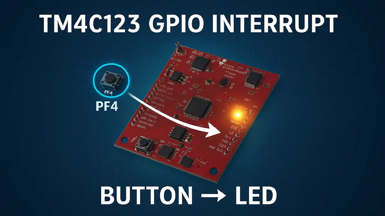
TM4C123 GPIO External Interrupts (Using TivaWare in Code Composer Studio)
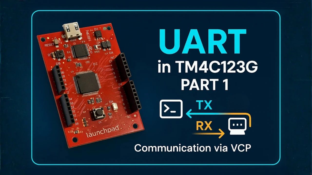
TM4C123G UART Tutorial (PART 1) – How to Use UART and Virtual COM Port in Tiva C

TM4C123G UART Tutorial (PART 2): Use Interrupt to Receive Data and Control LEDs

I2C in TM4C123G Tiva C – How to Use I2C Peripheral with TivaWare
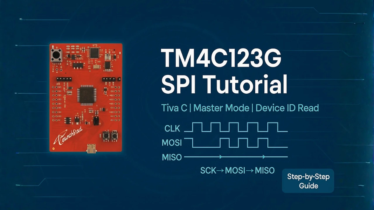
SPI Communication in TM4C123G: A Simple Guide
TM4C123G GPIO Project Download
TM4C123G GPIO FAQs
Subscribe
Login
0 Comments
Newest
