Published: February 4, 2026
Last Updated: April 1, 2026
Last Updated: April 1, 2026
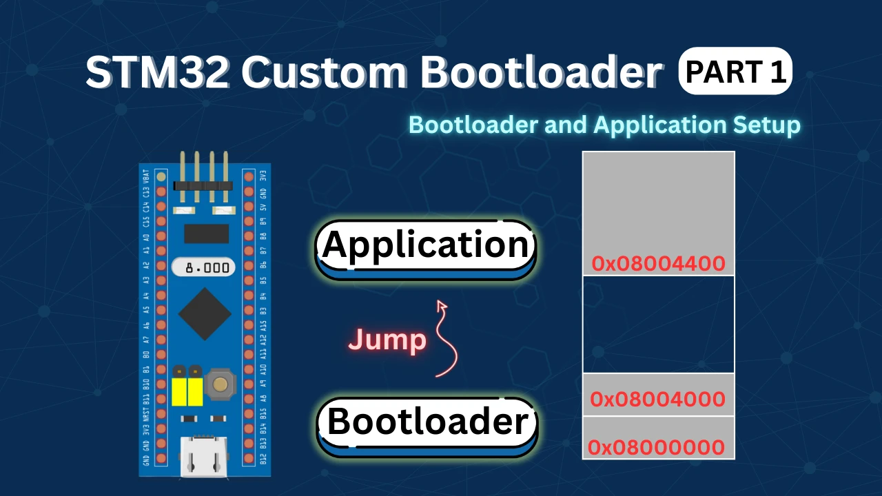
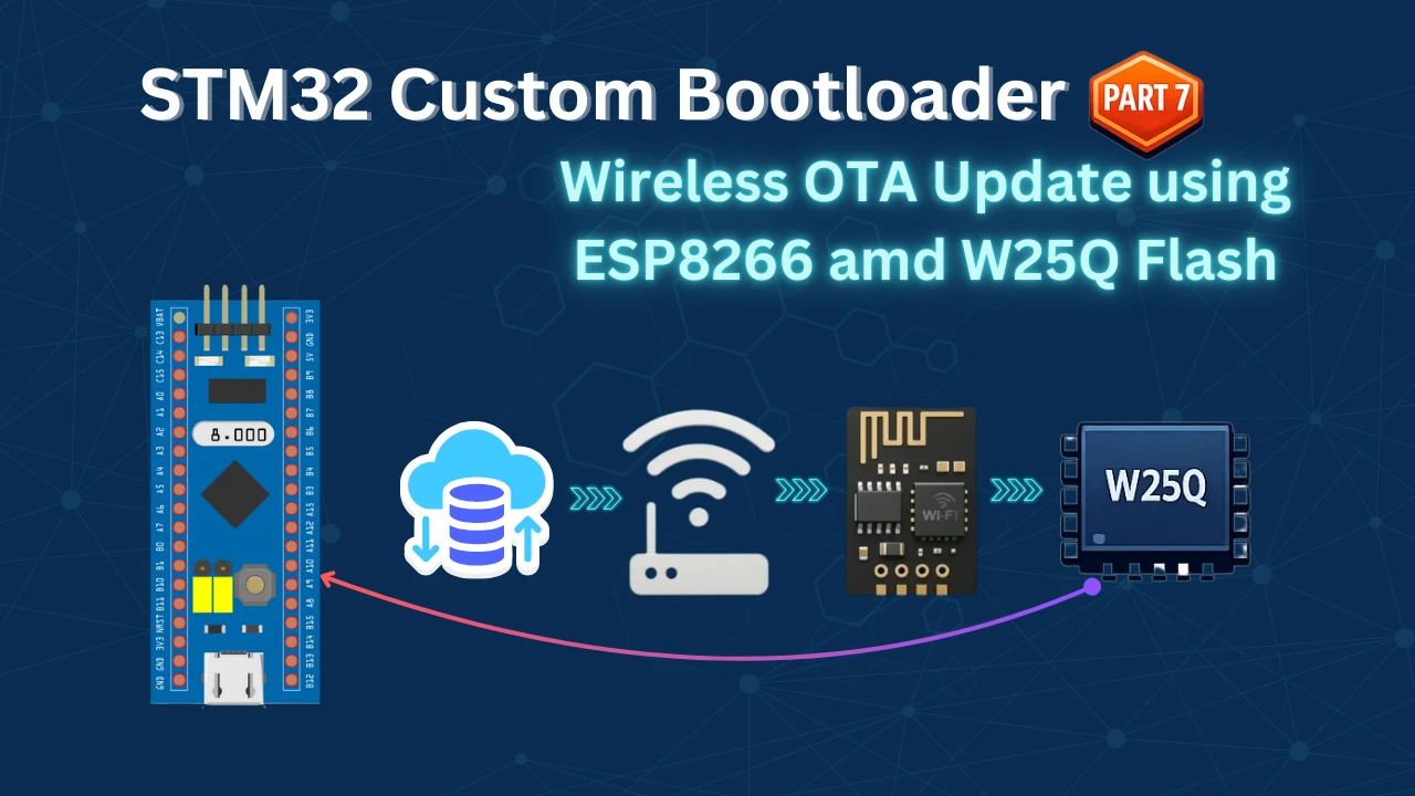
STM32 Wireless OTA Update Using ESP8266 and External Flash Memory
In the previous part of this STM32 Custom Bootloader series, we successfully implemented an OTA firmware update using Ethernet with the W5500 module. We downloaded the firmware from a TCP server and stored it in the internal flash memory. That worked great, but it still required a wired network connection.
In Part 7, we are going completely wireless.
This time, we will use the ESP8266 WiFi module to download the firmware update from a TCP server over WiFi. No more cables. No more network adapters. The STM32 will connect to your WiFi network, download the new firmware, and update itself automatically.
But there’s one more important change.
The STM32F103C8 has limited internal flash memory. We cannot split it like we did with the STM32F446. So instead of using internal flash, we will store the downloaded firmware in an external W25Q SPI flash memory. This gives us more flexibility and allows us to handle larger firmware files.
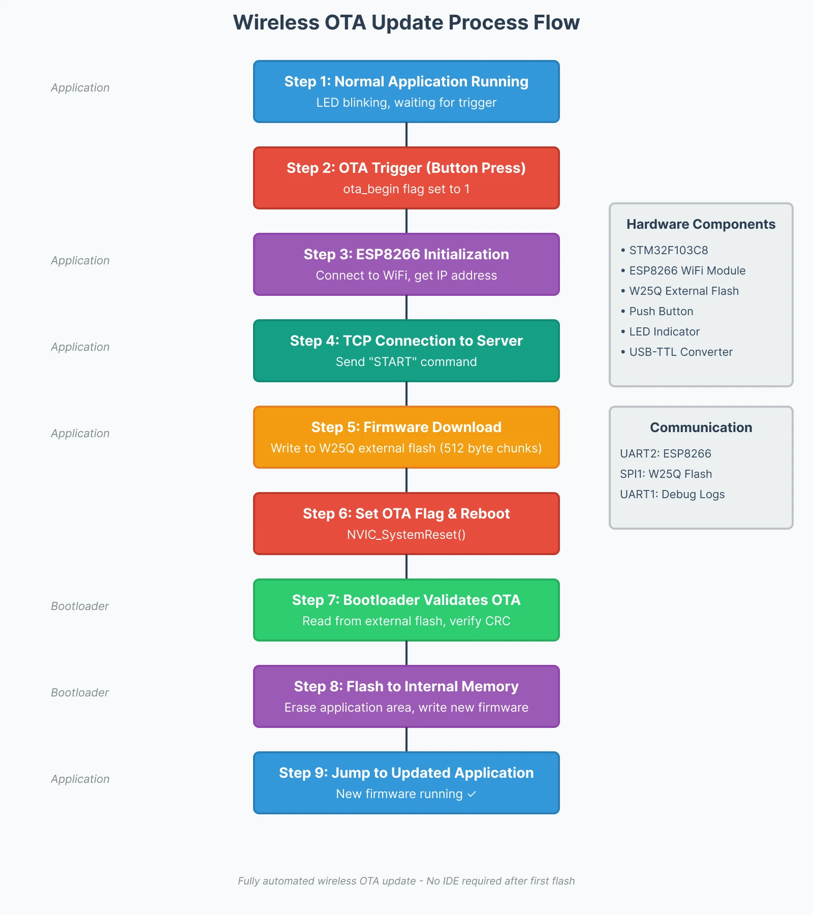
Here’s how the complete process works:
- The application receives a trigger signal from a push button
- ESP8266 initializes and connects to WiFi
- It connects to the TCP server and downloads the OTA firmware
- The firmware is stored in the W25Q external flash memory
- The system reboots automatically
- The bootloader reads the firmware from external flash
- It validates the firmware and writes it to internal flash
- Finally, the bootloader jumps to the updated application
This tutorial will show you how to configure the ESP8266 module, set up external flash memory, implement the wireless OTA client, and modify the bootloader to read firmware from external storage. We will also test the complete system and verify that the update works reliably.
Understanding the Wireless OTA System Architecture
Before we jump into the code and configuration, let’s understand why we’re using this specific architecture and how all the pieces fit together. This section will help you see the bigger picture and understand the design decisions we made for this wireless OTA system.
Why Use ESP8266 for Wireless OTA Updates
I chose the ESP8266 for this project because it removes the need for any physical network connection. In the previous tutorial, we used Ethernet with the W5500 module, which required an Ethernet cable connected to a router or computer. That works fine in lab environments, but it’s not practical for real-world IoT devices.
With the ESP8266, your STM32 device can connect to any WiFi network and download firmware updates from anywhere. You could have the device installed in a remote location, and as long as it has WiFi access, you can push updates to it wirelessly.
The ESP8266 also has a simple AT command interface, which we can use to:
- Connect to WiFi access points
- Establish TCP connections
- Send and receive data over the network
- Handle multiple connections if needed
External Flash Memory Benefits
In Part 6 of this series, we used internal flash memory to store the downloaded OTA image. We split the STM32F446’s 512KB flash into regions for the bootloader, application, and OTA storage. That approach worked well because the F446 has enough flash space.
But the STM32F103C8 only has 64KB of internal flash. We cannot split such a small flash into multiple regions without severely limiting the application size. This is where external flash memory becomes essential.
The W25Q series of SPI flash chips are small, affordable, and easy to interface with STM32. They come in different sizes, from 1MB to 128MB, which gives us plenty of room to store firmware updates. It communicates over SPI, which is a standard interface available on all STM32 microcontrollers. We just need four wires: CLK, MISO, MOSI, and CS. The read and write speeds are fast enough for OTA purposes, and the library to control these chips is simple and reliable.
Complete OTA Update Process Flow
Now let’s walk through the complete OTA update process from start to finish. This will help you understand how the application, bootloader, ESP8266, and external flash all work together.
Step 1: Normal Application Execution
When the STM32 boots up normally, the bootloader runs first. It checks if there’s a valid application in internal flash. If everything looks good, the bootloader jumps to the application, and the application starts running.
At this stage, the ESP8266 is not initialized, and no OTA process is active. The application just does its normal job, whatever that might be. In our demo, it blinks an LED to show that it’s running.
Step 2: OTA Trigger
To start the OTA process, we press a push button connected to the STM32. This button sets a flag in the application code. You could also trigger the OTA process using a network command, a timer, or any other condition, but for this tutorial, we’re using a simple button for demonstration.
Once the flag is set, the application knows it needs to start the OTA update sequence.
Step 3: ESP8266 Initialization and WiFi Connection
The application initializes the ESP8266 module by sending AT commands over UART. First, it resets the module to ensure a clean start. Then it configures the WiFi mode and connects to the access point using the SSID and password we defined in the code.
The ESP8266 sends back status messages, which the application monitors. Once the module successfully connects to WiFi and obtains an IP address, it’s ready to communicate over the network.
Step 4: TCP Connection to OTA Server
Next, the application tells the ESP8266 to connect to the TCP server. We provide the server’s IP address and port number. The ESP8266 establishes a TCP connection and waits for instructions.
Once connected, the application sends a simple “start” command to the server. This tells the server that the device is ready to receive the firmware update.
Step 5: Firmware Download and Storage
The TCP server starts sending the firmware file in small chunks, usually 512 bytes at a time. The ESP8266 receives these chunks and forwards them to the STM32 over UART.
The application reads the incoming data, processes it, and writes it directly to the W25Q external flash memory. Each chunk is written sequentially until the complete firmware image is stored.
To ensure reliable transfer, the application sends an acknowledgment (ACK) back to the server after each chunk. The server waits for this ACK before sending the next chunk. This simple flow control prevents data loss.
Step 6: OTA Flag and System Reboot
Once the entire firmware file is downloaded and verified, the application sets an OTA flag in a special memory location. This flag tells the bootloader that a new firmware update is available in external flash.
After setting the flag, the application resets the STM32 using the NVIC system reset function. The MCU reboots immediately.
Step 7: Bootloader Reads and Validates OTA
After the reboot, the bootloader runs again. This time, it detects the OTA flag and knows it needs to process a firmware update instead of jumping directly to the application.
The bootloader initializes the W25Q external flash and starts reading the firmware image. It verifies the OTA header, checks the CRC, and makes sure the firmware size is valid.
If everything passes validation, the bootloader continues to the next step. If validation fails, the bootloader clears the OTA flag and boots into the old application.
Step 8: Flashing New Firmware to Internal Flash
Once validation is complete, the bootloader erases the application region in internal flash. Then it reads the new firmware from external flash and writes it into internal flash, sector by sector.
After the entire firmware is written, the bootloader recalculates the CRC and updates the application header with the new version number and metadata.
Step 9: Jump to Updated Application
Finally, the bootloader jumps to the newly flashed application. The updated firmware starts running, and you can verify the version number to confirm the update was successful.
From this point forward, the device runs the new firmware. The OTA flag is cleared, and the system is ready for the next update whenever needed.
This entire process happens automatically. Once you press the button, the rest of the sequence runs without any user intervention. The application downloads the firmware, stores it safely, and signals the bootloader to flash it. The bootloader handles the update and boots into the new application.
The image below shows the complete OTA update flow diagram for better visualization.
Hardware Setup and Connection Diagram
Now that we understand the system architecture, let’s connect all the hardware components. This section shows you exactly how to wire the ESP8266, external flash memory, and other peripherals to the STM32F103C8 board.
The image below shows the complete wiring diagram used in this project. It includes the connection for ESP8266, W25Q Flash, FT232 USB to TTL converter, Button and the LED.
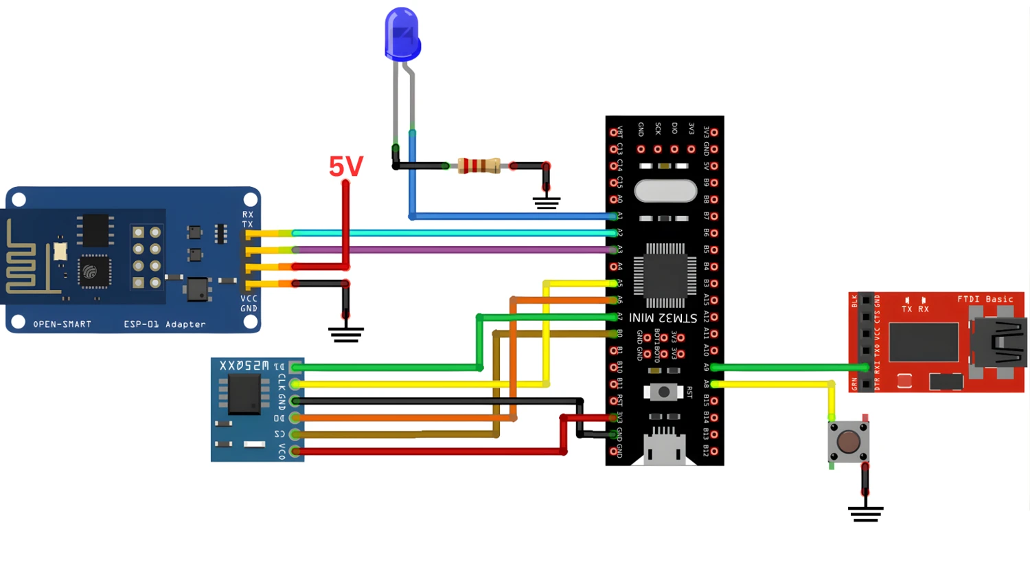
Let’s understand each component connection in detail.
ESP8266 WiFi Module Connection to STM32
The ESP8266 communicates with the STM32 using UART. We will use UART2 for this connection because UART1 is reserved for debugging.
I am using an ESP-Adapter to connect the ESP8266 module with STM32. This adapter helps reducing the number of connections required with the MCU. If you want to check out the ESP8266 communication with STM32 in depth, do checkout Connect STM32 to WiFi with ESP8266.
Here’s how to connect the ESP8266 to STM32:
| ESP8266 Adapter | STM32F103C8 |
|---|---|
| TX | PA3 (UART2 RX) |
| RX | PA2 (UART2 TX) |
| VCC (5V) | 5V |
| GND | GND |
Make sure the TX pin of the ESP8266 connects to the RX pin of the STM32, and vice versa. This is a common mistake that prevents communication. The ESP8266 operates at 3.3V, so never connect it to 5V. Although the adapter it is connected to, required 5V. Hence I have connected it to 5V.
Most ESP8266 modules are pre-configured to use 115200 baud rate for AT commands. We will use this same baud rate in our UART2 configuration.
W25Q External Flash Memory SPI Wiring
The W25Q flash memory uses SPI communication. We will connect it to SPI1 on the STM32. These chips are available in different sizes like W25Q16 (2MB), W25Q32 (4MB), or W25Q64 (8MB). Any of these will work fine for storing OTA firmware.
Here’s the SPI connection:
| W25Q Flash | STM32F103C8 |
|---|---|
| CLK | PA5 (SPI1 SCK) |
| MISO | PA6 (SPI1 MISO) |
| MOSI | PA7 (SPI1 MOSI) |
| CS | PB0 (GPIO Output) |
| VCC | 3.3V |
| GND | GND |
The CS (Chip Select) pin is controlled manually using a GPIO pin. We set it LOW when we want to communicate with the flash and HIGH when we’re done. The W25Q flash memory also operates at 3.3V, just like the ESP8266. Make sure all your power connections are correct and all ground pins are connected together.
USB to TTL Converter for Debug Logs
We need a way to see what’s happening during the OTA update process. For this, we connect a USB to TTL converter to UART1. This allows us to print debug messages to a serial terminal on our computer. We only need to receive the data from STM32, hence I have just used 1 pin.
Here’s the connection:
| USB-TTL Converter | STM32F103C8 |
|---|---|
| RX | PA9 (UART1 TX) |
Push Button and LED Indicator Setup
We need a push button to trigger the OTA update manually. This button is connected to a GPIO pin configured as an external interrupt.
We also need an LED to show that the application is running. This makes it easy to verify that the firmware update worked.
Here’s the simple connection:
| Component | STM32F103C8 |
|---|---|
| Push Button | PA1 (GPIO Input with Pull-up) |
| Button GND | GND |
| LED Anode (+) | PA0 (GPIO Output) |
| LED Cathode (–) | GND (through 220 Ω resistor) |
The push button is connected between PA1 and GND. We will enable the internal pull-up resistor in CubeMX, so when the button is not pressed, PA1 reads HIGH. When pressed, it reads LOW.
The LED is connected to PA0 through a current-limiting resistor. When PA0 is HIGH, the LED turns on. When LOW, it turns off.
The Application project
We will start with the Application project. We will first update the project with cubeMX, enabling the peripherals to include the new components. Then copy the required library files and finally modify the application code.
STM32CubeMX Configuration
We have already configured the UART1 for logs, a push button to trigger the OTA update and an LED to indicate the application running in the previous tutorial of this series. Now we need to enable the SPI for the W25Q Flash and another UART to communicate with the ESP8266.
SPI configuration for W25Q
The image below shows the SPI1 configuration for the W25Q flash memory.
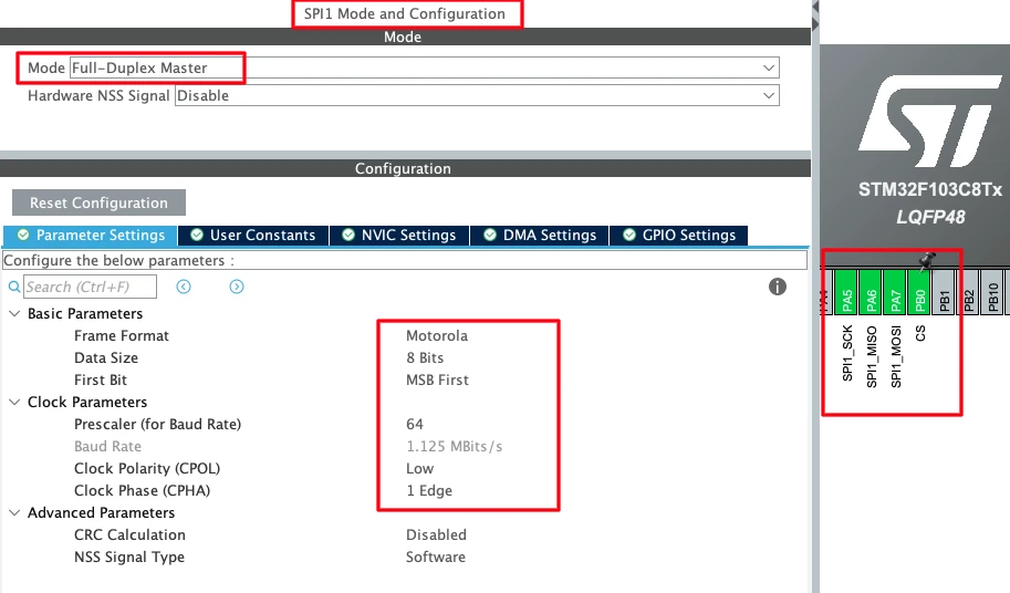
Enable the SPI in the Full-duplex mode with the following parameters:
Mode: Full-Duplex Master
Hardware NSS Signal: Disable
Data Size: 8 Bits
First Bit: MSB First
Set the prescaler so that the SPI baud rate stays close to 1 Mbps. Also set the clock polarity and phase:
Clock Polarity (CPOL): Low
Clock Phase (CPHA): 1 Edge
These settings are required by the W25Q flash memory datasheet. If these are wrong, the flash won’t respond correctly.
Once you enable SPI1, CubeMX automatically assigns the pins:
PA5 → SPI1_SCK (Clock)
PA6 → SPI1_MISO (Master In Slave Out)
PA7 → SPI1_MOSI (Master Out Slave In)
We also need to configure the GPIO pin for the Chip Select signal and I have configured PB0 for it. This in is configured in the output mode.
Configuring UART2 for ESP8266
Now we will configure UART2 to communicate with the ESP8266. The image below shows the UART configuration.
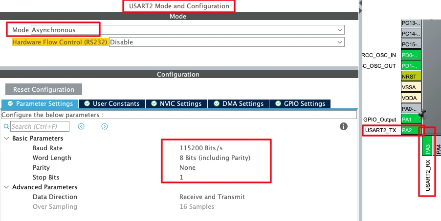
Set the baud rate to 115200. Most ESP8266 modules come pre-configured with this baud rate, so this is the safest choice.
Baud Rate: 115200 Bits/s
Word Length: 8 Bits
Parity: None
Stop Bits: 1
These are standard UART settings that work with almost all ESP8266 modules.
Once enabled, CubeMX assigns these pins:
PA2 → USART2_TX
PA3 → USART2_RX
Remember, PA2 (TX of STM32) connects to RX of ESP8266, and PA3 (RX of STM32) connects to TX of ESP8266.
Setting up the UART DMA
The ESP8266 will send large amounts of firmware data over UART2. If we use normal polling or interrupt mode, we might lose data because the CPU could be busy doing other things. DMA (Direct Memory Access) solves this problem by copying data directly from the UART peripheral to memory without CPU involvement.
The image below shows the DMA configuration for UART2 RX.
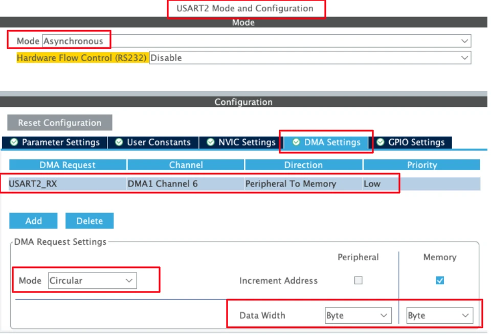
Go to the DMA Settings tab under USART2. Click Add to create a new DMA request.
Configure it as follows:
DMA Request: USART2_RX
Mode: Circular
Data Width: Byte
The Circular mode is very important. This means the DMA automatically restarts when it reaches the end of the buffer. We don’t need to manually reinitialize it after every packet.
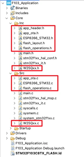
Adding the required libraries
We need to add the library files for the ESP8266 and the W25Q flash memory. I have also made some changes to the existing files we created in the previous parts of this series. You can get all the files used in the project by downloading the complete project at the end of this post.
The image below shows the application project structure with new library files included.
Configure the ESP8266 Library
After copying the library files, we must configure them according to our setup. Open the ESP8266_STM32.h file and update the UART instance for the ESP8266.
/* ------------ USER CONFIG ------------- */
#define ESP_UART huart2 // UART connected to ESP8266Next, open the ESP8266_STM32.c file and configure the network setting as shown below.
#define WiFi_ssid				"ssid"
#define WiFi_pssd				"password"
#define SERVER_IP               "192.168.1.6"
#define SERVER_PORT 5678Then open the W25Qxx.c file and update the SPI instance and memory size for the W25Q module.
#define W25Q_SPI hspi1

#define chipSizeinmb 32 // 32megabitsWriting the Main Application Code
Inside the main.c file, we will first implement a custom write function to route the printf output to the UART. This is necessary to get the debug logs to show up on the serial console.
int __io_putchar (int ch)
{
HAL_UART_Transmit(&huart1, (uint8_t *)&ch, 1, 10);
return ch;
}The OTA process will only start after the user press a button connected to the STM32. The button Pin is configured in the EXTI mode, hence when the button is pressed, an interrupt will trigger and a GPIO_EXTI callback will be called.
Inside this callback, we will set a variable ota_begin to start the the OTA update process.
void HAL_GPIO_EXTI_Callback(uint16_t GPIO_Pin)
{
ota_begin = 1;
}The rest of the code will run inside the while loop. Below is the complete while loop.
while (1)
{
if (ota_begin == 1)
{
HAL_Delay(500); // debounce
ota_begin = 0;
ota_start();
}
while (ota_active == 1)
{
ESP8266_OTA_Task();
HAL_Delay(1);
}
HAL_GPIO_TogglePin(GPIOA, GPIO_PIN_1);
HAL_Delay(500);
}Here if the ota_begin variable is set, we will start the OTA update process by calling the function ota_start().
This function is defined inside the ESP8266_STM32.c file and it is responsible for the following:
- It will initialize the ESP8266 module and connect to the provided WiFi access point.
- Then it will connect to the TCP server and wait for the connection to be established.
- Next, it will initialize the W25Q chip and send START command to the server, stating that it is ready to receive the data.
Once the OTA update process is started, the variable ota_active will set to 1. Inside the main while loop, we will create another infinite loop, which will run when this variable is set. The main purpose of this loop is to call the function ESP8266_OTA_Task(), which handles the incoming data from the ESP8266.
If the button is not pressed, the variable ota_begin will be 0 and the usual application will run normally.
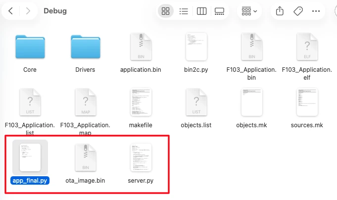
Preparing the OTA Image
After building the application, we need to generate the ota_image.bin file. To do this, use the app_final.py script file present in the debug folder of the project. There is also a server.py file, which creates a TCP server on the computer for testing the OTA update process.
You can modify this script to change the server IP or Port address according to your requirement.
The image below shows the files present inside the debug folder of the application project.
The Bootloader Project
We do not need to modify a lot in the bootloader project. It is already fully capable of flashing the OTA update. But since the bootloader needs to read the update file from the external flash memory, we do need to configure the cubeMX and add the W25Q library files.
CubeMX configuration
The image below shows the SPI1 configuration for the W25Q flash memory.
Enable the SPI in the Full-duplex mode with the following parameters:
Mode: Full-Duplex Master
Hardware NSS Signal: Disable
Data Size: 8 Bits
First Bit: MSB FirstSet the prescaler so that the SPI baud rate stays close to 1 Mbps. Also set the clock polarity and phase:
Clock Polarity (CPOL): Low
Clock Phase (CPHA): 1 EdgeThese settings are required by the W25Q flash memory datasheet. If these are wrong, the flash won’t respond correctly.
Once you enable SPI1, CubeMX automatically assigns the pins:
PA5 → SPI1_SCK (Clock)
PA6 → SPI1_MISO (Master In Slave Out)
PA7 → SPI1_MOSI (Master Out Slave In)We also need to configure the GPIO pin for the Chip Select signal and I have configured PB0 for it. This in is configured in the output mode.
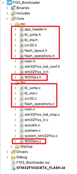
Adding the required libraries
We need to add the library files for the W25Q flash memory. I have also made some changes to the existing files we created in the previous parts of this series. You can get all the files used in the project by downloading the complete project at the end of this post.
The image below shows the bootloader project structure with new library files included.
Next, open the W25Qxx.c file and update the SPI instance and memory size for the W25Q module.
#define W25Q_SPI hspi1

#define chipSizeinmb			32	// 32megabits
Writing the Main Application Code
As I said, the bootloader is already capable of flashing the OTA, but we still need to update the way it reads the data from the update file. The OTA update is stored inside the W25Q external flash, therefore we need to update the Read function inside the main.c file.
int ota_read_mem(uint8_t *buf, uint32_t len)
{
    if (mem_cursor + len > ota_image_total_size)
        return -1;

    W25Q_FastRead(mem_base + mem_cursor, buf, len);

    mem_cursor += len;
    return 0;
}We created this function ota_read_mem() in the previous tutorials of this series. Here it is modified to read the data from the W25Q flash by calling the function W25Q_FastRead().
The rest of the bootloader logic will remain the same as we applied in the previous tutorials. Since it has been already explained, so I will skip it here.
Flashing the projects
Now both the projects are ready, so we will flash them to the STM32 board. Let’s start with the bootloader project first.
Flashing bootloader via cubeProgrammer
I will flash the bootloader project using the STM32CubeProgrammer. Before flashing the project, erase the entire flash memory to make sure we start everything clean.
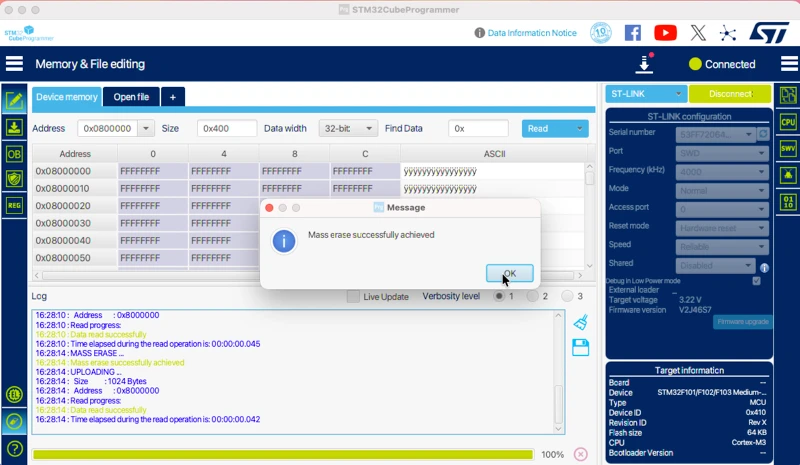
Once the flash is erased, download the bootloader project into the flash memory. You can use the ELF file to avoid the addressing input.
Flashing Application via cubeIDE
We need to run the application at least once in order to make the entire process work. Therefore we will run the application using the cubeIDE.
Open the application project, launch the debugger and create a new debug configuration. Go to the Startup tab and change the Start Address to 0x08004400. This is the start address of the application in the flash memory.
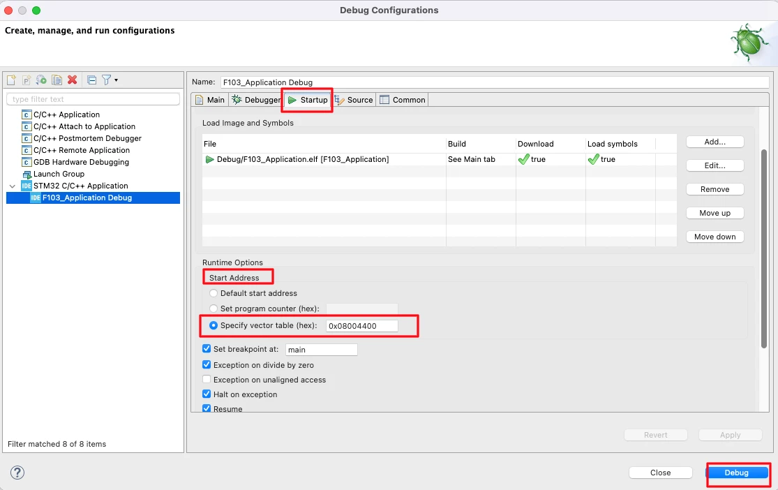
Once the debugger is launched, run the application.
Testing OTA Update Over WiFi
In this section, we will verify the complete OTA update flow over WiFi. At this stage, both the application and the bootloader are ready, and the TCP OTA server is running. Now we will observe how the system behaves before the update, during the OTA process, and after the new firmware is flashed.
Observing Server Logs
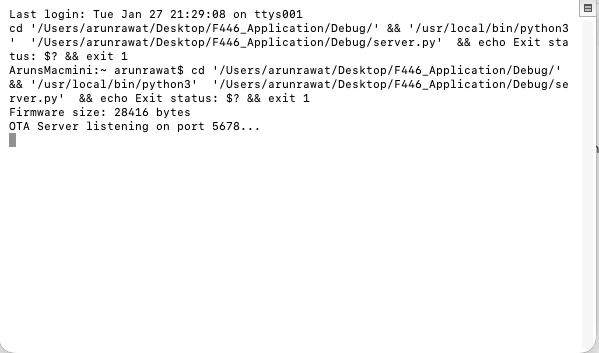
First, start the Python OTA server on your PC. Once the server starts, it begins listening for incoming TCP connections.
You should see logs indicating that the server is waiting for a client and is ready to send the OTA file. The image below shows the server logs displaying that the TCP server is listening and ready to accept a client connection.
OTA Download and Flash Process
We used the debugger to tun the application , so the application is already running on the STM32 board. Next, press the OTA trigger button on the STM32 board.
Once the button is pressed:
- The ESP8266 module is initialized along with W25Q flash
- An IP address is assigned
- The TCP client connects to the OTA server
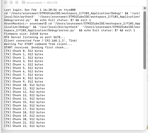
- The OTA request is sent to the server
The server then starts transmitting the OTA binary file. The image below shows the logs generated by the server.
On the client side, the firmware is received in chunks and written directly to the W25Q flash memory. The image below shows the logs generated by the application running on STM32.
It start by initializing ESP8266 module. Then it connects to the WiFI network and waits for the IP address to be obtained. Afterwards, it connects to the TCP server and sends OTA request.
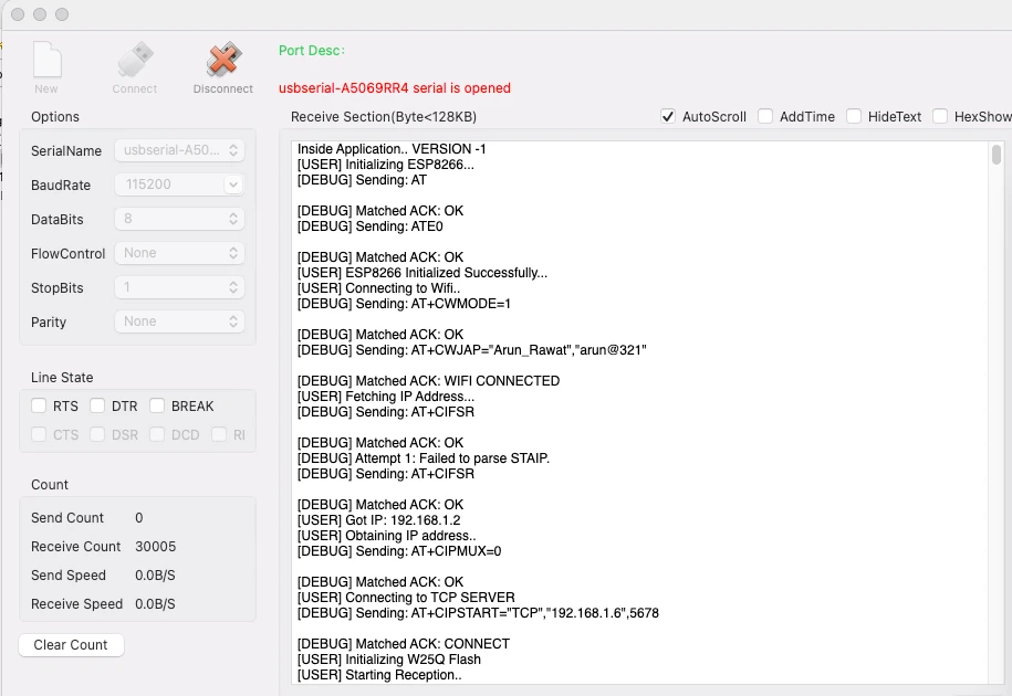
The client then receives all the data sent by the server. After the complete OTA image is received, the application resets the MCU.
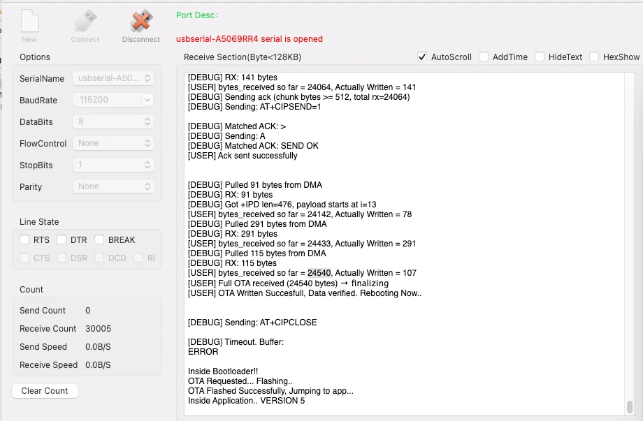
After the reset, the bootloader runs automatically.
The bootloader:
- Reads the OTA image from flash
- Verifies the firmware
- Flashes it into the application region
- Jumps to the new application
Now the updated application starts running.
Note:
You can check the video at the end of this post to see the complete working.
Verifying Application Version After OTA
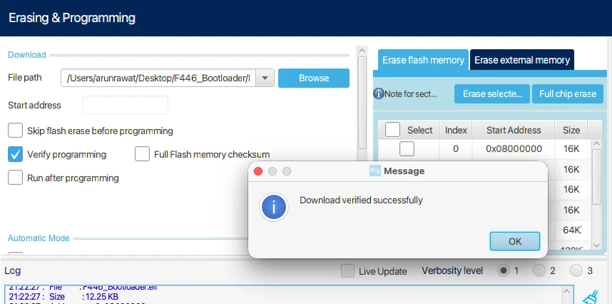
After the OTA update is complete and the system boots into the new firmware, we should always verify that the correct application has been flashed. The easiest and safest way to do this is by using STM32CubeProgrammer.
Reading Application Header from Flash
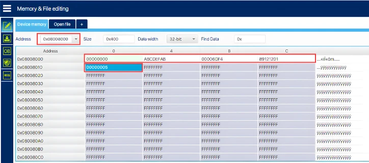
Open STM32CubeProgrammer and connect the STM32 using ST-Link. Once connected, go to the Memory & File Editing section. Here, read the flash memory region where the application header is stored.
The application header contains important metadata such as:
- Magic number
- Firmware size
- CRC
- Application version
This header is written by the bootloader after a successful OTA flash. The image below shows the application version field in STM32CubeProgrammer, confirming that the OTA update was applied successfully.
Video Tutorial
STM32 Wireless OTA Update Using ESP8266 – Complete Demo
In this video, we perform a complete wireless OTA update using the ESP8266 WiFi module. The application connects to WiFi, establishes a TCP connection to the server, downloads the firmware, stores it in W25Q external flash memory, and reboots automatically. After reset, the bootloader reads the OTA image from external flash, verifies it, flashes the new application to internal memory, and jumps to it.
The demo shows the entire process from button trigger to WiFi connection, firmware download, and successful application update running with a new version number.
Watch the Wireless OTA Update VideoConclusion and Next Steps
In this tutorial, we successfully implemented a fully wireless OTA firmware update system using the ESP8266 WiFi module and external flash memory. We learned how to configure the STM32F103C8 to communicate with the ESP8266 over UART, download firmware from a TCP server over WiFi, and store it in the W25Q external flash. The bootloader was then modified to read the firmware from external flash, validate it, and flash it into internal memory. This approach works perfectly for devices with limited internal flash and removes the need for any wired connections during updates.
The biggest advantage of this wireless OTA system is that it’s completely automated and requires no physical access to the device after the first flash. Once the initial bootloader and application are programmed, all future firmware updates can be pushed wirelessly over WiFi. The user simply triggers the update with a button press, and the entire process runs automatically. The application downloads the firmware, stores it safely, signals the bootloader, and reboots. The bootloader handles verification and flashing without any manual intervention. This makes it ideal for IoT devices deployed in remote locations.
This approach gives you flexibility in choosing your hardware and storage strategy. You can use the ESP8266 with internal flash storage on larger MCUs like the STM32F446, or combine it with external flash on smaller devices like the STM32F103C8. You can also switch between Ethernet and WiFi based on your project requirements. In future tutorials, we may explore additional features like rollback protection, encrypted firmware updates, or cloud-based OTA servers. For now, you have a complete, working wireless OTA system that you can adapt and use in your own projects.
More STM32 Bootloader Tutorials

STM32 Custom Bootloader (Part 2): Application Validation Using Magic Number
STM32 Custom Bootloader (Part 3): CRC Based Application Validation
STM32 Custom Bootloader (Part 4): Implementing OTA FLAG Mechanism
STM32 Custom Bootloader (Part 5): Implementing OTA Update
STM32 OTA Bootloader PART 6: Flash OTA Update from TCP Server Using Ethernet
STM32 Bootloader Project Download
STM32 Bootloader OTA FAQs
Subscribe
Login
0 Comments
Newest
