Published: November 1, 2025
Last Updated: February 6, 2026
Last Updated: February 6, 2026
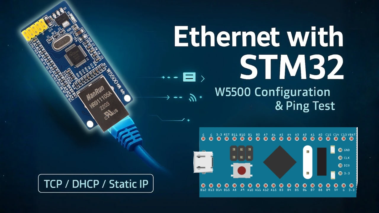
How to Interface W5500 Ethernet Module with STM32 via SPI
Ethernet connectivity can bring a whole new level of performance and reliability to your STM32 projects. In this tutorial, we’ll learn how to connect and configure the W5500 Ethernet module with STM32 using SPI.
I’ve already created an STM32 Ethernet series that covers the built-in Ethernet peripheral and the PHY LAN8742. However, that series focuses mainly on higher-end STM32 microcontrollers that include native Ethernet support. Many popular and cost-effective STM32 boards, especially the lower-end ones, don’t have this built-in Ethernet peripheral, which makes direct Ethernet connectivity impossible without an external module.
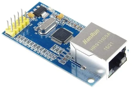
The W5500 from Wiznet is one of the most efficient Ethernet controllers, featuring a built-in hardware TCP/IP stack. This makes it perfect for STM32 boards that don’t have a built-in Ethernet peripheral.
We’ll go step by step -> starting from project setup in STM32CubeIDE, hardware connections, and library integration, to testing DHCP, Static IP, and perform Ping test.
Introduction to W5500 and STM32 Ethernet Interface
Ethernet communication allows STM32-based projects to connect directly to local networks or the internet for reliable, high-speed data transfer. However, not all STM32 microcontrollers come with a built-in Ethernet peripheral. That’s where external Ethernet modules like W5500 come in. The W5500 Ethernet module from Wiznet communicates via SPI, making it compatible with a wide range of STM32 boards, including cost-effective ones like the STM32F103 (Bluepill).
This tutorial series will guide you through enabling Ethernet connectivity on STM32 boards that don’t have native Ethernet support.
Why Use W5500 with STM32
The W5500 is a powerful and easy-to-use Ethernet controller designed specifically for embedded systems. It includes a built-in hardware TCP/IP stack, which means the STM32 doesn’t need to handle complex networking protocols in software. This offloads processing from the microcontroller, reduces CPU load, and improves overall performance.
Since the W5500 communicates using SPI, it can work with almost any STM32 MCU, even the low-cost ones without Ethernet hardware. It supports up to 8 simultaneous socket connections, provides 10/100 Mbps Ethernet, and includes a 32 KB internal buffer for smooth and efficient data transfer.
ENC28J60 vs W5500 – Which is Better for STM32 Projects
The ENC28J60 is another commonly used Ethernet module that also works via SPI. It’s cheaper and widely available, but it has a major drawback — it does not include a hardware TCP/IP stack. This means the STM32 must handle all network protocols using a software stack like lwIP, which increases CPU usage, consumes more flash and RAM, and slows down performance, especially when managing multiple connections.
In contrast, the W5500 processes TCP/IP operations internally, freeing the STM32 to handle other tasks. This makes it faster, more reliable, and ideal for real-time applications or IoT devices where efficiency matters.
The table below shows some key differences between ENC28J60 and W5500 Ethernet modules.
| Feature / Aspect | ENC28J60 | W5500 |
|---|---|---|
| Popularity & Availability | Very popular and easily available; low-cost option | Slightly costlier but also widely available |
| TCP/IP Stack Handling | Requires the MCU to handle the entire TCP/IP stack using software (like LWIP) | Has a built-in hardware TCP/IP stack, handled internally |
| MCU Resource Usage | High — consumes more Flash and RAM, and increases CPU load | Low — minimal MCU processing and memory required |
| Performance | Slower, especially with multiple connections or large data transfers | Faster and more stable due to hardware-based protocol handling |
| Simultaneous Connections | Limited (depends on software stack and available memory) | Supports up to 8 simultaneous socket connections |
| Data Buffer | No dedicated internal buffer; depends on MCU memory | 32 KB internal buffer for efficient data handling |
| Interface Speed | 10 Mbps Ethernet | 10/100 Mbps Ethernet |
| Ease of Integration with STM32 | Requires LWIP and more configuration effort | Simple SPI-based communication; works easily with most STM32 MCUs |
| Ideal Use Case | Suitable for simple or low-speed Ethernet applications | Recommended for high-performance and reliable Ethernet communication |
If your goal is to build a stable, high-performance Ethernet connection with minimal resource usage, W5500 is the clear winner.
What You Will Learn in This Tutorial
In this first part of the series, you’ll learn:
- How to connect the W5500 Ethernet module to an STM32 board using SPI
- How to configure the project in STM32CubeIDE
- How to set up DHCP and Static IP modes
- How to verify the connection using a ping test
- And finally, how to prepare for upcoming tutorials where we’ll create TCP and UDP servers for real data exchange
Setting Up STM32CubeIDE Project
To begin working with the W5500 Ethernet module, we first need to set up a new project in STM32CubeIDE. This setup includes selecting the right STM32 microcontroller, configuring the system clock, and enabling the required peripherals, mainly SPI for communication with the W5500 and UART for debugging and serial output.
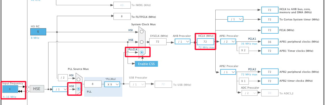
Configuring the Clock
- Enable the External High-Speed Crystal (HSE) as the clock source.
- The Bluepill board has an 8 MHz crystal oscillator, which we’ll use to run the system at 72 MHz, the maximum clock speed supported by this MCU.
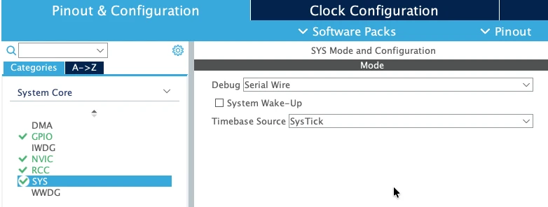
After this, go to System Core → SYS → Debug and enable Serial Wire Debug (SWD). This setting will allow you to program and debug the board through the ST-Link or a similar programmer.
SPI Peripheral Configuration for W5500
Now we’ll configure SPI1, which will be used to communicate with the W5500 module.
Open Connectivity → SPI1 and enable it in Full Duplex Master Mode, as the communication needs to work both ways.
The image below shows the SPI1 Configuration for this project.
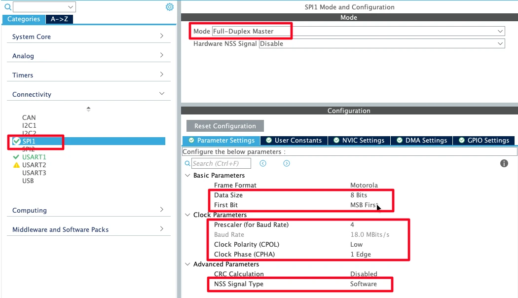
Make sure the settings are as follows:
- Data Size: 8-bit
- First Bit: MSB first
- Prescaler: Set to keep the SPI clock speed below 25 MHz (for example, 18 MHz is ideal)
- Clock Polarity (CPOL): Low
- Clock Phase (CPHA): 1st Edge (SPI Mode 0)
- NSS Signal: Software controlled (we’ll handle Chip Select manually through GPIO)
By default, the SPI pins PA5 (SCK), PA6 (MISO), and PA7 (MOSI) will be assigned automatically.
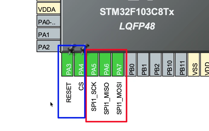
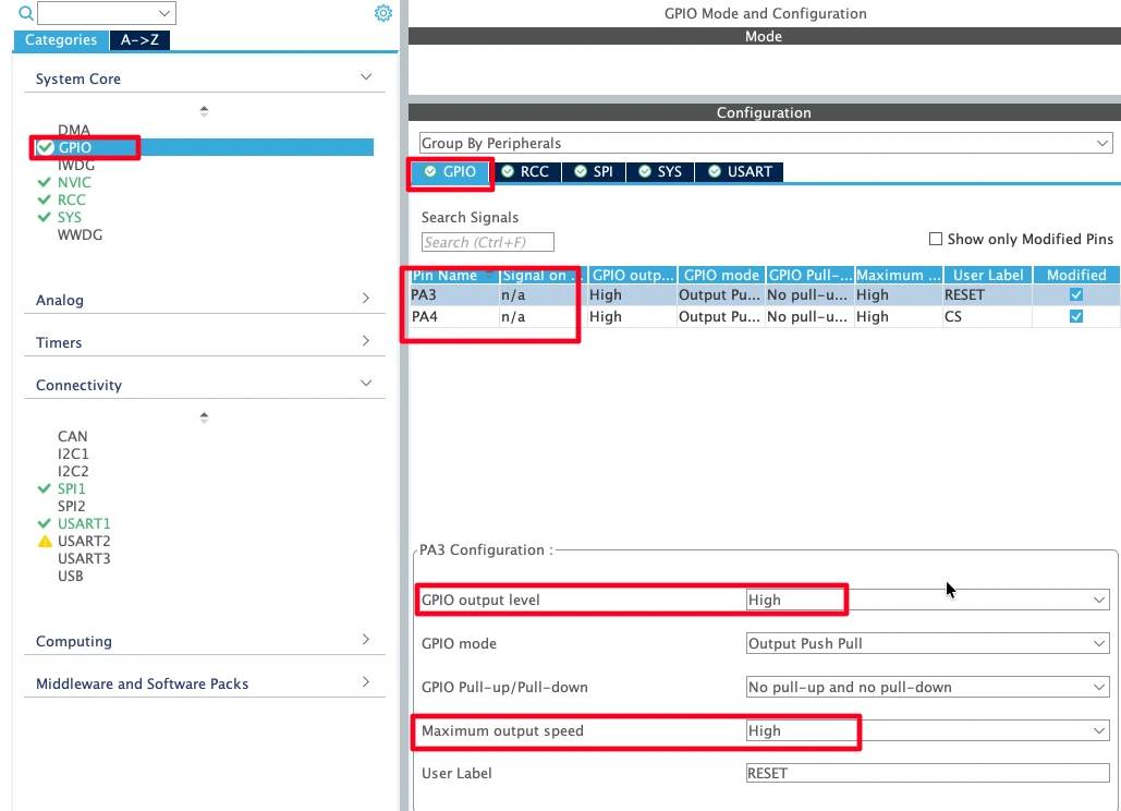
We’ll also define two extra GPIO pins: one for Chip Select (CS) and another for Reset (RST). Both should be configured as Output Push-Pull and named appropriately — CS and RESET.
Configuring UART for Serial Output
To monitor logs and debug information, we’ll configure UART1 for serial communication.
Enable USART1 from Connectivity → USART1 and set it to Asynchronous mode.
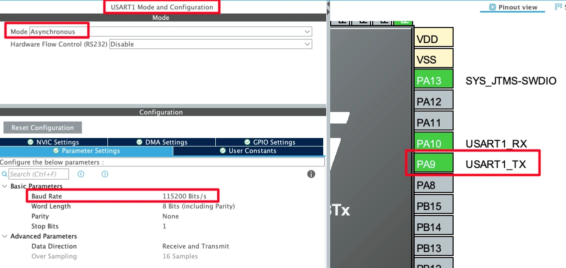
The TX pin (PA9) will be connected to the RX pin of the USB-to-TTL converter (like FT232). This setup allows you to view log messages on your computer using a serial monitor.
Finally, go to System Core → GPIO and ensure both the CS and RESET pins have their initial output level set to HIGH. This ensures the W5500 module remains in a safe state during power-up. Also, set the GPIO speed to High Output for faster signal transitions.
That’s all we need for the basic configuration.
Click Save to generate the initialization code, and STM32CubeIDE will automatically create all the necessary setup files for the project.
Connecting W5500 to STM32
Once the STM32 project is configured, the next step is to connect the W5500 Ethernet module to the STM32 board. Proper wiring is essential for reliable SPI communication and stable Ethernet operation. In this section, we’ll look at the pinout, power requirements, and UART connection for serial debugging.
W5500 Pinout and Wiring Diagram
The W5500 module from Wiznet has a standard pinout for SPI communication and control. The image below shows how the STM32F103C8 Dev board is connected to W5500 Ethernet Module and FT232 USB-to-TTL converter.
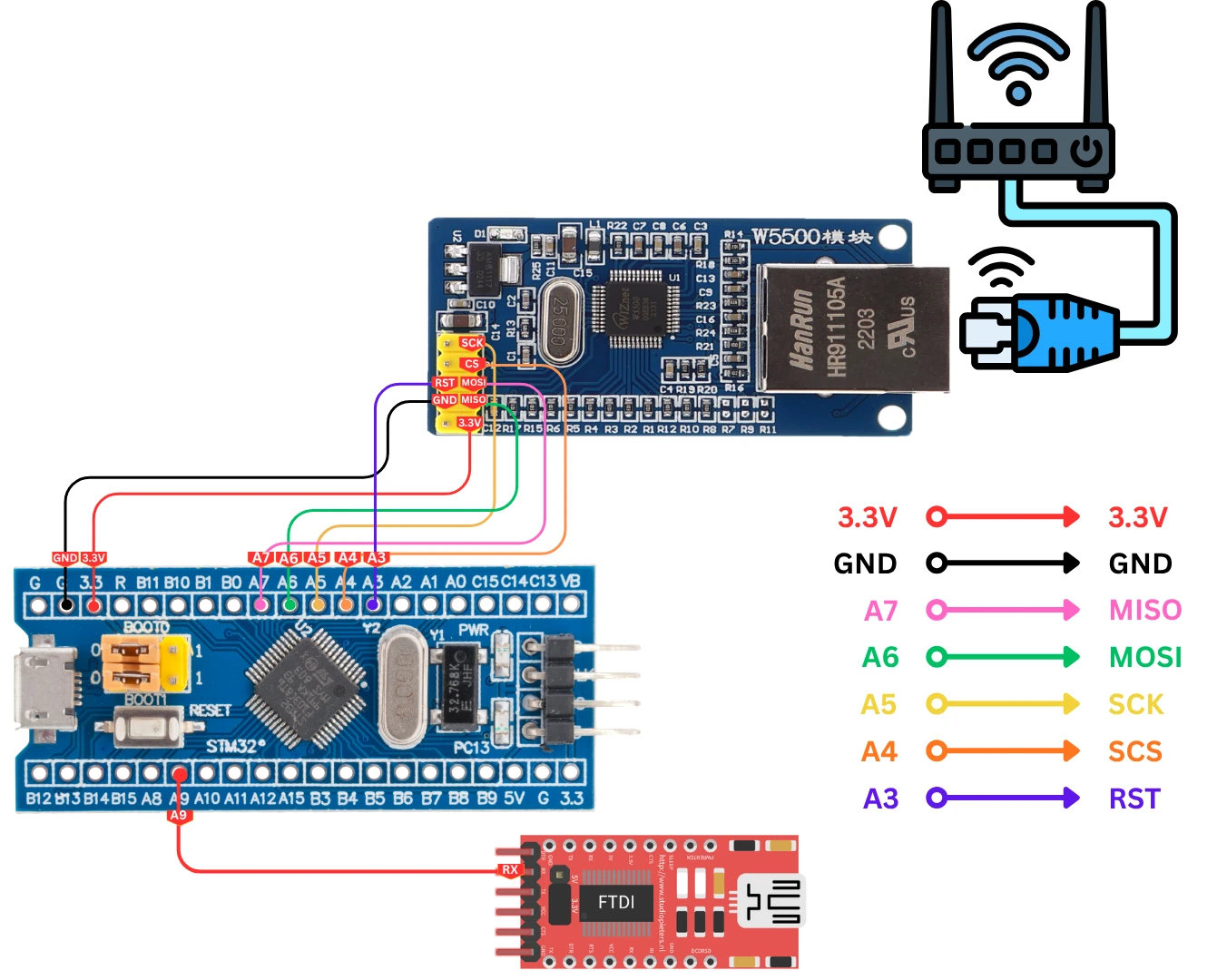
Here’s a quick overview of the important pins you’ll need to connect to the STM32:
| W5500 Pin | Function | STM32 Pin (Example – Bluepill) |
|---|---|---|
| SCS (CS) | Chip Select | PA4 |
| SCLK (SCK) | SPI Clock | PA5 |
| MISO | Master In Slave Out | PA6 |
| MOSI | Master Out Slave In | PA7 |
| RST | Reset Pin | PA3 |
| 3V3 | Power Supply | 3.3V Output |
| GND | Ground | GND |
You can follow this wiring whether you’re using the STM32F103, STM32F4, or similar boards. Make sure all grounds are connected together, this is very important for stable SPI communication.
Power Supply and Communication Pins
The W5500 module operates at 3.3V, so it can be powered directly from the STM32 board’s 3.3V pin. Do not power it from 5V, as that can permanently damage the IC.
For communication:
- The SPI pins (SCK, MISO, MOSI) handle data exchange between the STM32 and W5500.
- The CS (Chip Select) pin allows the MCU to enable or disable communication with the module.
- The RESET pin ensures proper startup of the W5500 and can be toggled by the STM32 if required.
The RJ45 port on the W5500 can be connected directly to your router or network switch using a standard Ethernet cable. This connection allows the W5500 to obtain an IP address through DHCP.
Otherwise if you would like to use the Static IP, connect the cable directly to your computer.
Connecting UART to USB-to-TTL Module
For monitoring logs, connect the STM32’s UART1 TX (PA9) pin to the RX pin of a USB-to-TTL converter such as the FT232 or CH340.
Here’s how to wire it:
| STM32 Pin | FT232 Pin | Function |
|---|---|---|
| PA9 (TX) | RX | Serial Data Output |
| GND | GND | Common Ground |
Once connected, plug the USB-to-TTL module into your computer and open a serial monitor (such as PuTTY or RealTerm) with the same baud rate you configured in STM32CubeIDE.
This setup will allow you to see initialization logs, IP configuration details, and debug messages from the STM32 in real time, which is extremely helpful for verifying that your W5500 module is communicating properly.
Adding Wiznet W5500 Library Files in STM32 Project
To make the W5500 work with STM32, we need to add the Wiznet IO Library to our project. This library contains all the essential files for handling SPI communication, IP configuration, and socket management for Ethernet communication. Once it’s added, you can easily create applications like TCP or UDP servers using simple API functions.
Downloading and Organizing the Wiznet IO Library
Wiznet provides an official IO Library for the W5500 module on their GitHub repository. You can either download the ZIP file or clone the repository using Git.
Once downloaded, extract the files and focus on the following folders:
- Ethernet/ → contains source files for W5500, socket handling, and DHCP.
- Internet/ → includes modules like DHCP, DNS, and loopback examples.
- wizchip_conf.h → contains all the configuration macros for the W5500 chip.
Create a new folder inside your STM32 project->Drivers directory (for example, name it Ethernet_W5500) and copy the required files into it.
Your project structure should now look something like this:
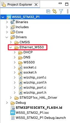
Here I have added the following files:
- wizchip_conf.h/.c → contains all the configuration macros for the W5500 chip.
- socket.h/.c → Implements the logic (functions and behavior) for managing network sockets.
- wizchip_port.h/.c → contains the functions to link the driver to STM32, like SPI functions. These files are written by me, so you won’t find them in the downloaded library.
- DNS & DHCP folders → contains the files related to the same. Use them if you want these functionality in your project.
- W5500 folder → contains the files needed to wrk with this chip.
Note: wizchip_port.h/.c are written by me, so you will not find them in the downloaded library. Once you download the project from the end of this article, you can find these files exactly where they are shown in the above image.
Configuring wizchip_conf.h and Adding Include Paths
Now, open the wizchip_conf.h file. This header file defines key configuration parameters and hardware interface functions for the W5500.
Here you need to define the wiznet chip you are using (W5500 in our case).
The image below shows the chip definition in the wizchip_conf.h file.
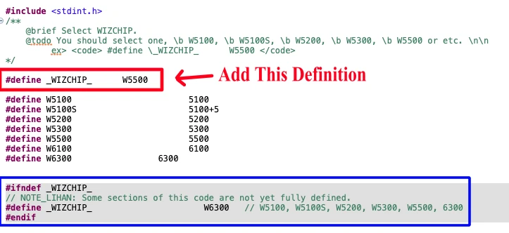
Once you define the chip in the wizchip_conf.h file, the predefined chip (in the blue box) will be greyed out.
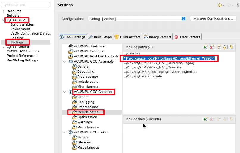
Next, go to Project Properties → C/C++ Build → Settings → MCU/MPU GCC Compiler → Include Paths, and add the path to the folder we just created (Ethernet W5500).
Understanding the wizchip_port.c File
The wizchip_port.c file acts as the connection bridge between your STM32 hardware and the W5500 Ethernet module. It handles the SPI communication, network configuration, and pin operations required for the module to function properly. Understanding this file is important because it defines how the STM32 interacts with the W5500 at the hardware level.
Configuring SPI and UART Handlers
At the top of the wizchip_port.c file, you’ll find definitions for the SPI and UART handlers. These handlers specify which peripherals on the STM32 are used for communication with the W5500 and for printing logs on the serial console.
If you have already configured SPI and UART in STM32CubeMX, simply link those handlers here — no extra setup is required.
For example:
#define W5500_SPI hspi1
#define LOG_UART huart1This ensures that all SPI transfers and debug messages go through the correct interfaces.
Enabling DHCP or Using Static IP
Next, the file allows you to choose between DHCP and Static IP configuration.
- Set
USE_DHCPto 1 if you want the W5500 to automatically obtain an IP address from the router. - Set it to 0 if you prefer to assign a fixed IP address manually.
When using a static IP, you’ll define your IP address, subnet mask, gateway, and DNS server directly in the file. If DHCP is enabled, these values will be overwritten once the module successfully obtains the IP information from the network.
Network Information Setup and Pin Configuration
The next section defines your network parameters such as:
- MAC address – a unique hardware address for the module
- IP address, Subnet mask, Gateway, and DNS server
wiz_NetInfo netInfo = {
    .mac = {0xAA, 0xBB, 0xCC, 0xDD, 0xEE, 0xFF},
    .ip = {192, 168, 1, 10},
    .sn = {255, 255, 255, 0},
    .gw = {192, 168, 1, 1},
    .dns = {8, 8, 8, 8},
#if USE_DHCP
	.dhcp = NETINFO_DHCP
#else
    .dhcp = NETINFO_STATIC
#endif
};The MAC address can be any random but valid value, while the other fields depend on your local network setup. If you’re using static IP, make sure the assigned IP is in the same subnet as your router or computer.
Finally, you’ll find two important functions to handle the Chip Select (CS) and Reset (RST) pins:
W5500_CS_LOW()/W5500_CS_HIGH()control the SPI chip select line.W5500_RST_LOW()/W5500_RST_HIGH()handles the reset sequence of the W5500.
If you have already named these pins (CS and RESET) in STM32CubeMX, the functions will automatically use those definitions, so you don’t need to modify anything here.
Initializing W5500 in STM32
Once the hardware and libraries are properly set up, the next step is to initialize the W5500 Ethernet module and verify its network connection. This process is handled by the W5500_init() function, which performs everything from resetting the chip to configuring the network parameters.
W5500_init() Function Explained
The W5500_init() function is the main initialization routine that prepares the W5500 for communication.
When called inside the main() function, it performs several key steps:
- Resets the module – Executes a hardware reset sequence to ensure the chip starts clean.
- Registers SPI callbacks – Links the SPI read and write functions, allowing data exchange between STM32 and W5500.
- Initializes the chip – Checks the chip status and reads the hardware version number. If everything is correct, it should return the version
0x04. - Checks network link – Verifies that the Ethernet cable is connected. It performs multiple retries until the link is detected.
If any step fails, the initialization process will stop and log an error message via UART.
DHCP, Static IP, and Network Configuration Steps
Once the link is established, the module proceeds with network configuration.
Depending on whether DHCP is enabled or not, the steps differ slightly:
- If DHCP is enabled (
USE_DHCP = 1):
The module requests an IP address from the router. It performs up to 20 retries, waiting around 500 ms between each attempt.
Once successful, the assigned IP address, Gateway, Subnet Mask, and DNS are automatically applied to the chip. - If using Static IP (
USE_DHCP = 0):
The pre-defined network information fromwizchip_port.cis written directly to the module.
This method is ideal when you want a fixed IP or are testing without a router.
After the network parameters are set, the function initializes the DNS and prints all configuration details, including IP, subnet, gateway, and DNS.
Using the W5500 with DHCP
We will first see how to use the module with DHCP to obtain the IP address. To enable the DHCP, make sure the USE_DHCP is set to 1 in the wizchip_port.c file.
#define USE_DHCP 1Inside the main.c file, include the wizchip_port.h file and call the function W5500_init() inside the main() function.
int main()
{
....
....
if (W5500_Init() != 0)
Error_Handler();
while (1)
{}
}Viewing Logs and Ping Test Results
All the initialization logs are printed on the serial console through UART. These logs show the entire process, from chip initialization to DHCP configuration, making it easier to debug connection issues.
The image below shows the initialization logs printed on the serial console.
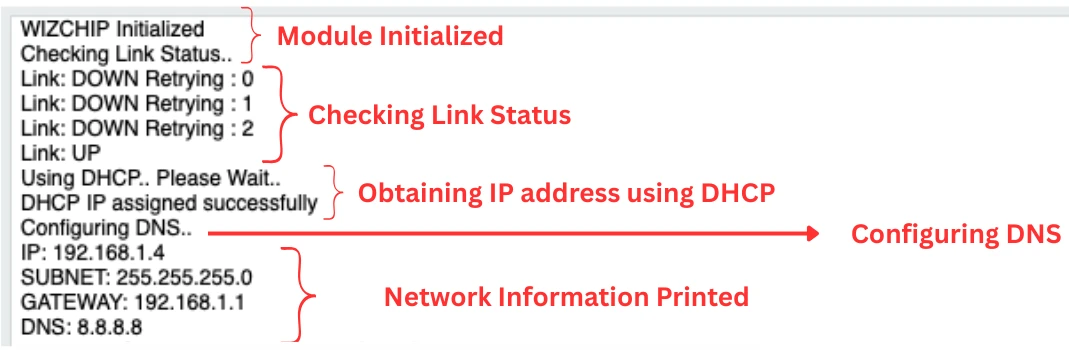
As you can see in the image, after initialization, the code checks for the link connectivity. Even thought the link is connected, it still takes some time to detect it. Once detected, it will obtain the IP address using the DHCP.
Next, after configuring the DNS, it prints all the network information on the serial console. This network information include:
- IP address: 192.168.1.4
- Subnet Mask: 255.255.255.0
- Gateway: 192.168.1.1
- DNS: 8.8.8.8
Once the IP address is obtained, you can perform a ping test from your computer or any device on the same network. If the ping responds successfully, it confirms that the W5500 is properly initialized and communicating with the network.
The image below shows the result of the ping test using my computer, which is connected to the same network via WiFi.
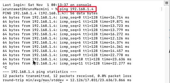
This simple test validates both the hardware connection and the network configuration, ensuring that your STM32 and W5500 setup is working perfectly before moving to higher-level protocols like TCP or UDP.
Using W5500 with Static IP
If you do not have the access to the router, you can still use static IP to test your project. To do so, connect the Ethernet cable directly between the computer and the W5500 Ethernet Module.
To use the Static IP, make sure the USE_DHCP is set to 0 in the wizchip_port.c file.
#define USE_DHCP 0The module will not be able to obtain the IP address automatically, therefore we need to configure it ourselves. The network information structure is defined at the top of the wizchip_port.c file.
wiz_NetInfo netInfo = {
    .mac = {0xAA, 0xBB, 0xCC, 0xDD, 0xEE, 0xFF},
    .ip = {192, 168, 1, 10},
    .sn = {255, 255, 255, 0},
    .gw = {192, 168, 1, 1},
    .dns = {8, 8, 8, 8},
#if USE_DHCP
	.dhcp = NETINFO_DHCP
#else
    .dhcp = NETINFO_STATIC
#endif
};Inside the main.c file, include the wizchip_port.h file and call the function W5500_init() inside the main() function.
int main()
{
  ....
  ....
    if (W5500_Init() != 0)
	  Error_Handler();
  while (1)
  {}
}Configuring Your Computer for Static IP Communication
When using a static IP with the W5500 module, it’s important to configure your computer’s Ethernet interface so both devices are on the same network. This ensures smooth communication between the STM32 board and your PC.
Start by connecting the RJ45 cable directly between your computer and the W5500 module. Once connected, the Ethernet adapter should become active.
Now, open your computer’s network settings and locate the Ethernet interface. You’ll need to manually assign an IPv4 address, do not use automatic (DHCP) mode.
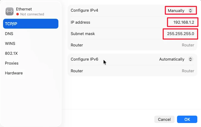
If your W5500 module’s gateway is set to 192.168.1.1, then your computer’s IP address must be within the same subnet but unique, Here I have configured it to 192.168.1.2.
For example, you can use something like 192.168.1.2 to 192.168.1.254.
Keep the Subnet Mask as 255.255.255.0, and set the Gateway to 192.168.1.1 (or whatever gateway you defined for the module).
Once configured, save the settings and close the network window. Your computer is now ready to communicate directly with the W5500 module using the assigned static IP.
Note: If you’re on macOS or Linux, make sure Wi-Fi is disabled while testing, as the operating system may prioritize the wireless network over the wired one, which could prevent successful ping responses.
Viewing Logs and Ping Test Results
All the initialization logs are printed on the serial console through UART. These logs show the entire process making it easier to debug connection issues.
The image below shows the initialization logs printed on the serial console.
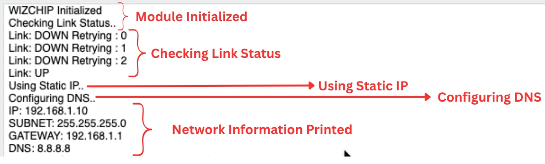
As you can see in the image, after initialization, the code checks for the link connectivity. Even thought the link is connected, it still takes some time to detect it. Once detected, it will use the static IP address.
Next, after configuring the DNS, it prints all the network information on the serial console. This network information include:
- IP address: 192.168.1.10
- Subnet Mask: 255.255.255.0
- Gateway: 192.168.1.1
- DNS: 8.8.8.8
You can see that the IP address printed on the console is the same as what we configured in the network parameters.
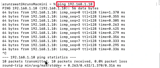
Now you can perform a ping test from your computer, which is connected to the W5500 module via Ethernet cable. If the ping responds successfully, it confirms that the W5500 is properly initialized and communicating with the network.
The image below shows the result of the ping test. You can see the Ping to the static IP 192.168.1.10 is successful.
Video Tutorial
STM32 W5500 Ethernet Interface Video Tutorial
This video demonstrates how to interface the W5500 Ethernet module with STM32 using the SPI protocol. It covers the complete setup — hardware connections, CubeIDE configuration, and testing the module using both DHCP and static IP.
Watch the W5500 TutorialConclusion and Next Steps
As we wrap up this first part of the STM32 Ethernet series, let’s quickly review what we’ve accomplished and what’s coming next.
Summary of What We Achieved
In this tutorial, we successfully connected the W5500 Ethernet module to an STM32 microcontroller using the SPI interface. We explored how to configure the SPI and UART peripherals, include the required Wiznet library files, and initialize the module using the W5500_init() function.
We also learned how to set up both DHCP and Static IP configurations, view logs through UART, and verify network connectivity using the ping test. By the end of this tutorial, your STM32 board should be able to establish a stable Ethernet connection and respond to network pings successfully.
What’s Coming Next – Custom TCP Server
In the next part of this series, we’ll go beyond the basics and create a custom TCP server on STM32 using the W5500 module. This server will allow the STM32 to receive, process, and respond to data from a client over the Ethernet network, making it a powerful starting point for IoT and embedded networking applications.
Browse More STM32 W5500 Tutorials
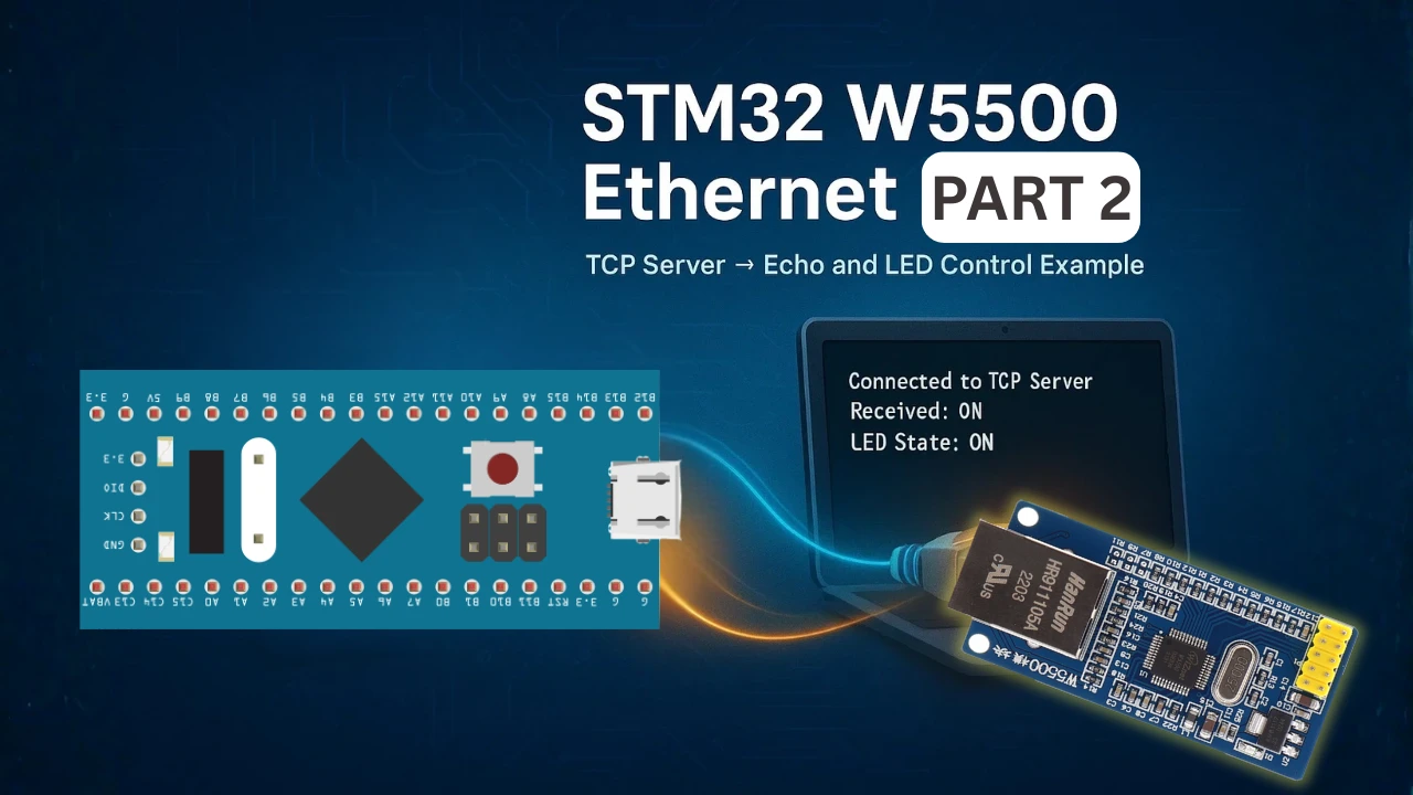
STM32 W5500 Ethernet Tutorial (PART 3): TCP Server with FreeRTOS
STM32 W5500 Ethernet Tutorial (Part 4): Connect STM32 to TCP Server Using DNS and Static IP
STM32 W5500 Ethernet Tutorial (Part 5): HTTP Webserver on STM32
STM32 W5500 Ethernet Tutorial (Part 6): Dynamic HTTP Webserver using CGI

Hi,
After following your instructions, I have an issue regrading to perform ping test while using static IP from another device to check the connection to module but seems not working properly it says the destination is unreachable, also I’m very sure about settings the IP. Could you guide me?
This is most probably due to wrong ethernet configuration in the computer. Make sure you configure the IP, subnet and gateway properly in the ethernet setting on your computer.