Published: January 13, 2026
Last Updated: April 1, 2026
Last Updated: April 1, 2026
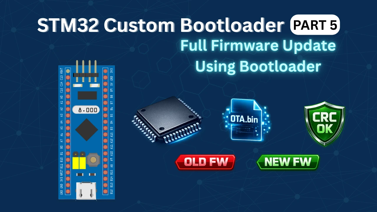
How to flash the OTA update from the STM32 Bootloader
This tutorial is Part 5 of the STM32 Custom Bootloader series. In the previous parts, we designed the memory layout, created the application header, added CRC, and implemented the OTA flag mechanism. We also learned how the button can trigger the OTA process. However, the bootloader was not flashing any real firmware yet.
In this part, we finally flash a real OTA image from the bootloader. The bootloader will read the OTA image, write it into flash memory, verify it using CRC, update the application header, and then jump to the new firmware.
In STM32 systems, this is done using a flag based bootloader. The bootloader checks a special OTA flag stored in flash memory. If the flag is set, it knows that a new firmware is available and starts the OTA process. If not, it simply jumps to the existing application.
In this tutorial, we will use this flag mechanism along with CRC and versioning to build a reliable STM32 OTA bootloader system.
OTA Update Architecture for STM32
To understand how an STM32 OTA bootloader works, we must first understand how the flash memory is organized and how the bootloader and application work together. Both the bootloader and the application live inside the same internal flash memory, but they use different regions. The bootloader always runs first after reset. Based on the OTA flag and application header, it decides whether to flash a new firmware or jump to the existing one.
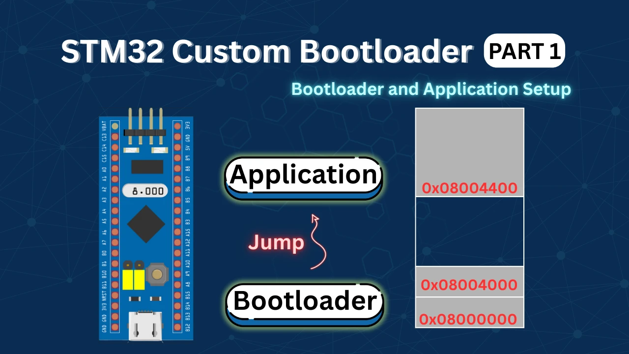
Flash Memory Layout
In an STM32 OTA system, the flash memory is split into two main areas. One area is used by the bootloader and the other by the application.
A simple layout looks like this:
|------------------------|
|   Bootloader           |
|------------------------|
|   Application Header   |
|------------------------|
|   Application Code     |
|------------------------|The bootloader is stored at the start of flash. This area normally never changes. The application header is placed just before the application code. This header holds important information about the firmware. The application code is the firmware that will be updated through OTA.
Every time the STM32 resets, it starts executing from the bootloader. The bootloader reads the header and decides what to do next.
Application Header Structure
The application header is a small data structure stored in flash. It describes the firmware that is currently installed.
In this project, the application header looks like this:
typedef struct
{
    uint32_t ota_flag;
    uint32_t magic;
    uint32_t size;      // application size in bytes
    uint32_t crc;       // CRC32 of application
    uint32_t version;
} app_header_t;Each field has a clear purpose.
- The ota_flag tells the bootloader whether a new firmware needs to be flashed.
- The magic number helps the bootloader check if the header is valid.
- The size stores the application size in bytes.
- The crc stores the CRC32 value of the firmware.
- The version helps track different firmware builds.
This header is written by the bootloader after a successful OTA update. The application binary itself does not contain this header in flash. The bootloader creates it after verifying the firmware.
OTA Flag Working
The OTA flag is the main control signal of the entire update system. It is stored as the first word of the application header.
The bootloader reads this flag directly from flash using this function:
uint32_t flash_read_ota_flag(void)
{
    __IO uint32_t *flash_ptr = (__IO uint32_t *)APP_HEADER_ADDR;
    return flash_ptr[0];
}This function reads the first 32-bit word from the application header address. That word is the OTA flag.
If the returned value is 1, it means an OTA update is required. The bootloader will start flashing the new firmware.
If the value is 0, it means the firmware is valid, and the bootloader will jump to the application.
After the bootloader successfully flashes a new firmware, it clears this flag and writes the full application header. This marks the firmware as valid and ready to run.
This simple flag-based design makes the STM32 OTA update process safe, fast, and reliable.
Application Side OTA Request Implementation
Before the bootloader can flash a new firmware, the application must prepare a proper OTA image. This image contains the firmware along with its metadata, such as size, CRC, and version. In this section, we will see how the application is prepared, how the OTA binary is generated, and how CRC and version are handled.
Since the actual OTA download is not implemented yet, we will simulate this behaviour using an external button. This helps us clearly understand the flow without adding extra complexity.
OTA Flag Location in Flash Memory
The OTA request flag is stored in the application header. Placing the OTA flag inside the application header has several advantages:
- The bootloader already knows where to read this data
- The flag survives reset and power cycles
- No extra flash region is required
In this implementation, the OTA flag is stored as the first word of the application header.
0-> No OTA request1-> OTA request active
Only this single word is modified during the OTA request. The rest of the application header remains unchanged.
Using External Button to Trigger OTA
In a real system, the OTA request would be triggered after:
- Downloading firmware from a server
- Verifying the downloaded image
Since this part is not implemented yet, we use a push button to simulate the OTA request.
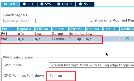
The button is connected to:
- PA8 configured as an external interrupt (EXTI)
- Internal pull-up resistor enabled
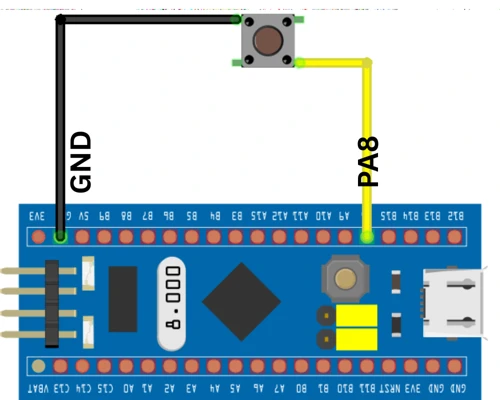
When the button is pressed:
- The pin goes low
- An external interrupt is generated
- The application starts the OTA request process
This approach makes testing easy and allows us to manually control the OTA flow.
GPIO EXTI Callback for OTA Request
When the button is pressed, the GPIO EXTI callback function is executed. The code below shows the EXTI callback used in the application.
void HAL_GPIO_EXTI_Callback(uint16_t GPIO_Pin)
{
    uint32_t wait = 10000;
    while (wait--);

    enable_ota_request();
}This callback does not directly modify flash memory. Instead, it calls a dedicated function that safely handles flash operations.
Application Header and Metadata
The application itself does not write the final application header into flash. That job is done by the bootloader after a successful OTA update.
However, the OTA image must still contain the metadata required by the bootloader. This metadata includes the application size, CRC, version, and magic number. This data is added to the binary file before it is flashed.
The actual application code only contains the firmware logic. In our test firmware, we use UART output and LED blinking to confirm that the new firmware is active.
HAL_UART_Transmit(&huart1, (uint8_t *)"Inside Test Application!!\r\n", 27, 100);
while (1)
{
    HAL_GPIO_TogglePin(GPIOA, GPIO_PIN_1);
    HAL_Delay(100);
}This code prints a message on the serial terminal and toggles the LED every 100 ms. When OTA is complete, this behavior confirms that the new firmware is running.
Generating OTA Binary
After building the application in STM32CubeIDE, a raw binary file (application.bin) is created in the Debug folder. This binary only contains the application code.
This file is then processed using the app_final.py script. The purpose of app_final.py is to:
- Read the application binary
- Calculate the application size
- Calculate the CRC32
- Add the magic number and version
- Append this metadata to the end of the binary
After running this script, a new file is created called ota_image.bin.
This file is the final OTA firmware. It contains both the application code and its metadata in a single binary.
CRC and Version Handling
The CRC32 is calculated inside app_final.py using the application binary. This CRC is stored inside the OTA metadata that is appended to ota_image.bin.
When the bootloader flashes this OTA image, it recalculates the CRC while writing the data to flash. At the end, both CRC values are compared. If they do not match, the firmware is rejected.
hdr = struct.pack(
    "<IIII",
    0xABCDEFAB,   # magic
    size,
    crc,
    0x04    # version
)The version number is also defined inside app_final.py. Every time a new firmware is built, this version should be increased. After a successful OTA update, the bootloader writes this version into the application header.
This makes it easy to track which firmware is running on the STM32.
Creating ota_image.h
The bootloader does not directly use ota_image.bin. Instead, for this tutorial, we convert it into a C header file. This is done using the second Python script bin2c.py. This script takes ota_image.bin and converts it into a C array.
The output file is ota_image.h.
This file contains the OTA firmware as a byte array. It is copied into the bootloader project and included in the code. The bootloader reads the OTA data directly from this array and flashes it into application flash memory.
Later, when TCP or HTTP is used, this header file will no longer be needed. But for now, it makes testing very simple and reliable.
Bootloader OTA Engine (bl_OTA.c)
The OTA engine is the heart of the STM32 OTA bootloader. It controls the full update flow, from reading the OTA image to flashing it and validating it. This file works like a small state machine. Each function runs in sequence and moves the OTA process forward until the new firmware is ready to run.
In this section, we will see how the bootloader reads the OTA header, validates the image, and flashes the firmware while checking the CRC.
Reading OTA Header
The first step of the OTA process is to read the OTA image header. This header is stored at the start of the OTA image and contains all important metadata.
Inside bl_ota_run(), the bootloader reads this header from the OTA stream.
ota_image_hdr_t hdr;

/* Read OTA header */
if (stream->read((uint8_t *)&hdr, sizeof(hdr)) != 0)
return -1;This header contains the magic number, firmware size, CRC, and version. Without this information, the bootloader cannot safely flash the firmware.
Once the header is read, the bootloader knows how large the application is and how much data must be received.
Validating Image
After reading the header, the bootloader checks whether the image is valid.
if (hdr.magic != APP_MAGIC)
    return -2;

if (hdr.image_size == 0 || hdr.image_size > APP_MAX_SIZE)
return -3;The magic number confirms that this is a valid OTA image.
The image size ensures that the firmware fits inside the application flash region.
Only if both checks pass does the bootloader continue with the OTA process.
At this point, the bootloader also tells the OTA stream how much data it will read.
uint32_t total_size =
    sizeof(ota_image_hdr_t) + hdr.image_size;

if (stream->set_total_size)
stream->set_total_size(total_size);This allows the stream layer to manage how much data remains.
Flashing and CRC Check
Once the image is validated, the actual flashing process starts.
bl_ota_begin(ctx, hdr.image_size, hdr.crc);This function erases the application flash area, prepares the context, and initializes the CRC engine.
The firmware data is then read in small chunks and written into flash.
while (remaining)
{
    uint32_t len = (remaining > sizeof(buf)) ? sizeof(buf) : remaining;

    if (stream->read(buf, len) != 0)
        return -4;

    if (bl_ota_write_chunk(ctx, buf, len) != 0)
        return -5;

    remaining -= len;
}Each chunk is written to flash, and the running CRC is updated at the same time. This ensures that every byte of the firmware is verified.
After all data is written, the bootloader finalizes the OTA.
if (bl_ota_finalize(ctx, &hdr) != 0)
return -6;This step compares the calculated CRC with the expected CRC from the OTA header. If they match, the bootloader writes the application header, clears the OTA flag, and marks the firmware as valid.
If anything fails, the bootloader stays active and does not jump to the application. This makes the OTA system safe and reliable.
OTA Stream Interface
The bootloader does not care where the OTA file comes from. It only knows how to read data using a stream. This design makes the OTA system very flexible. The data can come from a header file, internal flash, external flash, TCP, or even an HTTP server. All of this is handled by the OTA stream interface.
In this section, we will see how the OTA stream is defined, how a memory-based reader works, and how the OTA image stored as a C header is used.
OTA Stream Structure
The OTA stream is defined using a simple structure inside the bl_ota.h file. It contains two function pointers.
typedef struct
{
    int  (*read)(uint8_t *buf, uint32_t len);
    void (*set_total_size)(uint32_t total_size);
} ota_stream_t;The read() function is used to fetch data from the OTA source.
The set_total_size() function tells the stream how much data will be read in total.
The bootloader OTA engine uses only these two functions. It does not need to know where the data is coming from.
Memory Based OTA Reader
For this tutorial, the OTA image is stored inside flash as a C array. So we use a memory-based reader.
Some internal variables are used to track where we are reading from.
static uint32_t mem_base = 0;
static uint32_t mem_cursor = 0;
static uint32_t ota_image_total_size = 16; // OTA header sizeThe total OTA image size is updated after reading the OTA header.
void ota_mem_set_total_size(uint32_t size)
{
    ota_image_total_size = size;
}The read function copies data from the OTA image into a buffer.
int ota_read_mem(uint8_t *buf, uint32_t len)
{
    if (mem_cursor + len > ota_image_total_size)
        return -1;

    memcpy(buf, &ota_image_bin[mem_base + mem_cursor], len);

    mem_cursor += len;
    return 0;
}This function simply reads data from the OTA image array. If the OTA is stored in external flash or received from a server, this function can be replaced with the correct reader.
Using Header Based OTA Image
The OTA image is included in the bootloader as ota_image.h. This file contains the firmware as a byte array. When the OTA flag is set, the bootloader creates the stream and starts the OTA engine.
if (check_ota_request() == 0)
{
    ota_stream_t stream =
    {
        .read = ota_read_mem,
        .set_total_size = ota_mem_set_total_size
    };

    bl_ota_ctx_t ctx;

    if (bl_ota_run(&ctx, &stream) != 0)
    {
        while (1)
        {
            HAL_GPIO_TogglePin(GPIOA, GPIO_PIN_4);
            HAL_Delay(500);
        }
    }
}If the OTA update fails, the red LED blinks slowly.
If it succeeds, the bootloader continues to validate the application.
int err = bootloader_is_app_valid();

if (err != 0)
{
    while (1)
    {
        HAL_GPIO_TogglePin(GPIOA, GPIO_PIN_4);
        HAL_Delay(100);
    }
}If the application is valid, the bootloader jumps to it.
JumpToApplication();This stream-based design allows the same OTA engine to work with any data source. Only the read function needs to change.
How read() changes for different OTA sources
The OTA engine always does this internally:
stream->read(buffer, length);It does not know if the data is coming from:
- A C header
- External flash
- Ethernet
- Wi-Fi
- SD card
Only the implementation of read() changes.
W25Q External SPI Flash OTA
Let’s say your OTA image is stored in W25Q at address 0x000000.
static uint32_t w25q_base   = 0x000000;
static uint32_t w25q_cursor = 0;
static uint32_t ota_image_total_size = 0;

void ota_w25q_set_total_size(uint32_t size)
{
    ota_image_total_size = size;
}

int ota_read_w25q(uint8_t *buf, uint32_t len)
{
    if (w25q_cursor + len > ota_image_total_size)
        return -1;

    W25Q_Read(buf, w25q_base + w25q_cursor, len);   // SPI Flash read

    w25q_cursor += len;
    return 0;
}Stream setup:
ota_stream_t stream =
{
    .read = ota_read_w25q,
    .set_total_size = ota_w25q_set_total_size
};The OTA engine doesn’t know it’s reading SPI flash, it just sees bytes.
Ethernet / TCP OTA (W5500)
Here the OTA image is coming over a TCP socket.
static uint32_t tcp_bytes_received = 0;
static uint32_t ota_image_total_size = 0;

void ota_tcp_set_total_size(uint32_t size)
{
    ota_image_total_size = size;
}

int ota_read_tcp(uint8_t *buf, uint32_t len)
{
    if (tcp_bytes_received + len > ota_image_total_size)
        return -1;

    int r = TCP_Recv(buf, len);   // blocking read from W5500
    if (r != len)
        return -1;

    tcp_bytes_received += len;
    return 0;
}Stream setup:
ota_stream_t stream =
{
    .read = ota_read_tcp,
    .set_total_size = ota_tcp_set_total_size
};Now OTA works over LAN without touching the OTA engine.
UART OTA
Firmware coming via UART.
static uint32_t uart_rx_count = 0;
static uint32_t ota_image_total_size = 0;

void ota_uart_set_total_size(uint32_t size)
{
    ota_image_total_size = size;
}

int ota_read_uart(uint8_t *buf, uint32_t len)
{
    if (uart_rx_count + len > ota_image_total_size)
        return -1;

    HAL_UART_Receive(&huart1, buf, len, HAL_MAX_DELAY);

    uart_rx_count += len;
    return 0;
}Stream update:
ota_stream_t stream =
{
    .read = ota_read_uart,
    .set_total_size = ota_uart_set_total_size
};SD Card OTA
Firmware stored in firmware.bin on SD card.
static FIL file;
static uint32_t ota_image_total_size = 0;

void ota_sd_set_total_size(uint32_t size)
{
    ota_image_total_size = size;
}

int ota_read_sd(uint8_t *buf, uint32_t len)
{
    UINT br;
    if (f_read(&file, buf, len, &br) != FR_OK)
        return -1;

    if (br != len)
        return -1;

    return 0;
}Stream update:
ota_stream_t stream =
{
    .read = ota_read_sd,
    .set_total_size = ota_sd_set_total_size
};Flashing and Testing OTA Update
Before we move to advanced OTA sources like Ethernet or WiFi, we must first confirm that the complete OTA chain works correctly. In this section, we will program the bootloader, trigger the OTA update, and verify that the new firmware is really running on the STM32.
Flashing the bootloader
We only flash the bootloader, not the application. This is because the bootloader itself will handle flashing the application during the OTA process.
You can flash the bootloader in two ways:
- Directly from STM32CubeIDE
- Or by using STM32CubeProgrammer
When using CubeProgrammer:
- Connect the ST-Link to the board.
- Open the Download tab.
- Browse to the bootloader binary file.
- Set the address to the start of flash memory, 0x08000000
- Click Start Programming.
At this point, only the bootloader is inside the MCU. The application will be written later by the OTA engine.
Triggering OTA update
After flashing the bootloader, reset the board. At this point the old application should run.
Now press the button to trigger the OTA. This sets the OTA flag and forces the MCU to reset.
On restart, the bootloader detects the OTA request and starts flashing the new firmware from the OTA image.
During this process:
- The old application is erased
- The new firmware is written
- CRC is verified
- The application header is updated
If something goes wrong, the bootloader will stay active and the LED will indicate failure.
Verifying new firmware
Once flashing is complete, the bootloader jumps to the new application. The image below shows the log printed on the serial console.
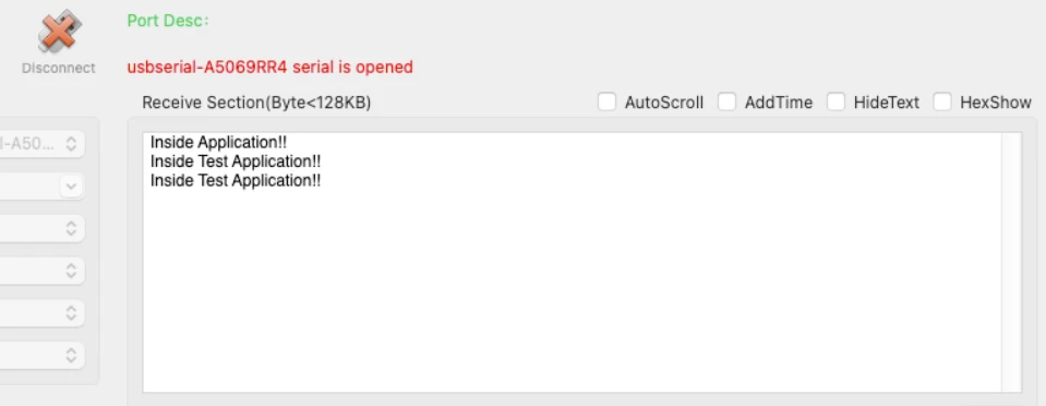
The Green LED on STM32 blinks every 100ms confirming that the new application is running.

This confirms that:
- The new binary was written
- The CRC matched
- The version was updated
- The bootloader jumped correctly
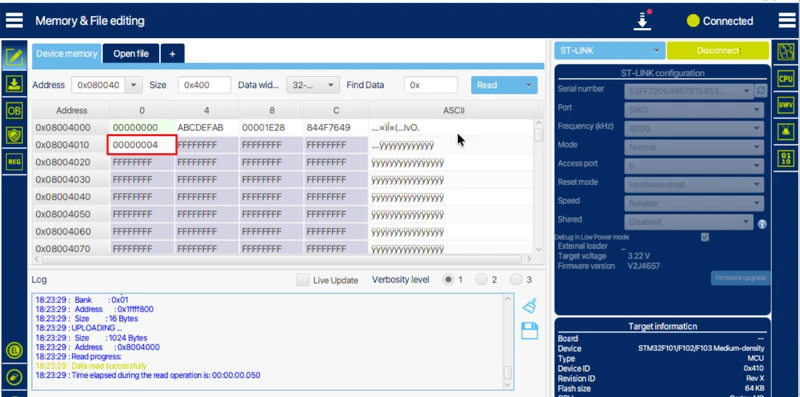
You can also connect the board to STM32CubeProgrammer and check the application header. The version field should now show the new version number, proving that the OTA update worked.
At this point, your STM32 OTA bootloader is fully functional and ready to receive firmware from memory, SD card, Ethernet, or WiFi in the next parts of this series.
Video Tutorial
STM32 OTA Bootloader – Full Update Demo
Watch how the STM32 bootloader reads an OTA image, checks its CRC, flashes it into memory, and jumps to the new firmware. The video also shows how a button triggers the OTA process and how the updated application runs after flashing.
Watch the STM32 OTA VideoConclusion
In this part 5 of the STM32 OTA Bootloader series, we built a complete and working OTA update system. We covered the memory layout, application header, OTA flag mechanism, OTA image generation, CRC validation, stream-based OTA reading, and the bootloader OTA engine. We also tested the full flow by flashing the bootloader, triggering the OTA update, and verifying that the new firmware runs correctly on the STM32.
This design is very powerful because it makes the bootloader independent of where the firmware comes from. The same OTA engine can work with internal flash, external flash, SD card, or even data received from Ethernet or WiFi. The OTA flag and application header make the update safe, while CRC ensures data integrity. This gives you a reliable and scalable STM32 OTA update solution.
In the next parts of this series, we will remove the manual steps. The application will download the firmware from HTTP or TCP servers, store it in flash, and trigger the OTA automatically. This will give us a fully automated remote firmware update system for STM32, which is ideal for real-world IoT and embedded products.
More STM32 Bootloader Tutorials

STM32 Custom Bootloader (Part 2): Application Validation Using Magic Number
STM32 Custom Bootloader (Part 3): CRC Based Application Validation
STM32 Custom Bootloader (Part 4): Implementing OTA FLAG Mechanism
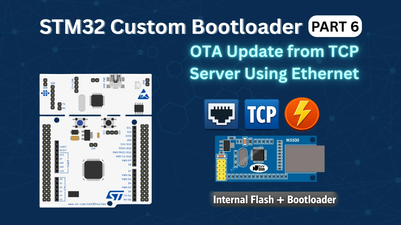
STM32 OTA Bootloader PART 6: Flash OTA Update from TCP Server Using Ethernet
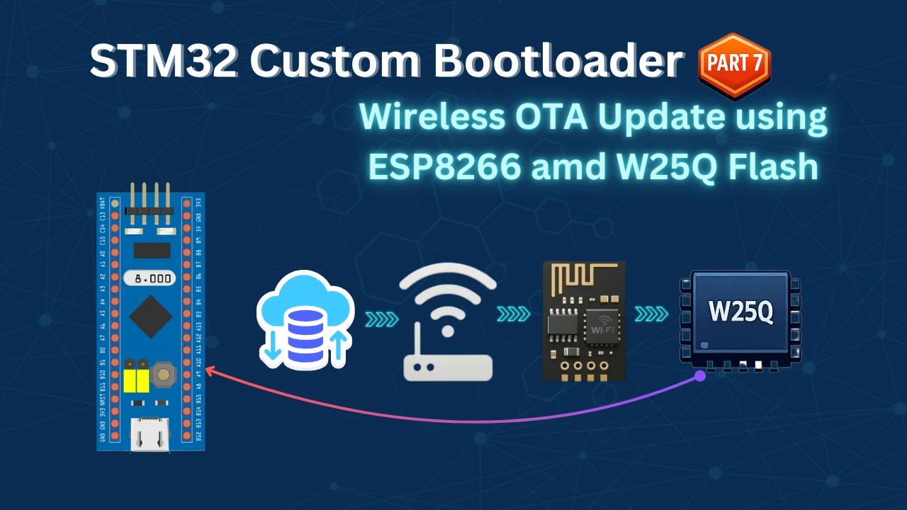
STM32 OTA Bootloader (PART 7): Wireless Firmware Update Using ESP8266 WiFi Module
STM32 Bootloader Project Download

STM32 Bootloader OTA FAQs
Subscribe
Login
0 Comments
Newest
