Home ▸ STM32 Tutorials ▸
Published: July 11, 2025
Last Updated: March 23, 2026
Last Updated: March 23, 2026
Interface SD Card via SDIO (4Bit Mode & DMA)
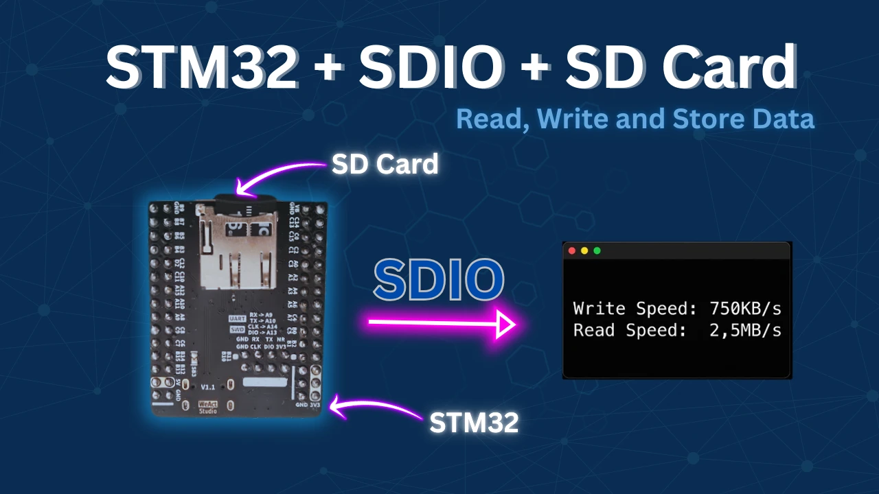
In this tutorial, we cover how to interface an SD card with an STM32 microcontroller using the SDIO peripheral, which is specifically designed for high-speed SD card communication. The provided library also supports DMA-based data transfers, allowing data to move directly between memory and the SD card with minimal CPU intervention. This significantly improves read and write performance compared to polling-based methods, making it suitable for data logging, file systems, and storage-intensive embedded applications.
The SDIO-based implementation supports most commonly used SD card types, including SDSC (Standard Capacity), SDHC (High Capacity), and SDXC (eXtended Capacity) cards. This flexibility ensures compatibility across a wide range of storage sizes and use cases. Additionally, if you are interested in a simpler or more universally supported approach, we have already covered SD card interfacing using SPI with DMA in a separate tutorial, which you can refer to here:
https://controllerstech.com/interface-sd-card-with-stm32-via-spi-dma/
Introducing SDIO Peripheral
The SDIO (Secure Digital Input Output) peripheral in STM32 microcontrollers is a dedicated hardware interface used for communication with SD cards and MMC cards. It offers high-speed data transfer and is optimized for SD memory access, making it a superior alternative to the traditional SPI interface when working with SD cards.
Unlike SPI, which is a general-purpose serial communication protocol, SDIO is specifically designed to interface with SD cards using the native SD protocol. This allows for faster read/write speeds, lower CPU overhead, and more efficient data handling, especially when combined with DMA (Direct Memory Access).
Some of its features are:
- High-Speed Data Transfer: Supports up to 4-bit data width, enabling much faster transfer rates compared to 1-bit SPI mode.
- DMA Support: Seamless integration with DMA controllers offloads the CPU, allowing background data transfers.
- Dedicated Hardware Interface: Uses dedicated SDIO peripheral registers and hardware logic for optimized SD card operations.
- Multiple Transfer Modes: Supports Polling, Interrupt, and DMA modes, making it flexible for various application needs.
Below is the table showing the comparison between SPI and SDIO.
| Feature | SPI Interface | SDIO Interface |
|---|---|---|
| Protocol Type | General-purpose serial (SPI) | SD card native protocol (SDIO) |
| Data Bus Width | 1-bit | Up to 4-bit |
| Transfer Speed | Up to ~25 Mbps | Up to ~100 Mbps (depends on card & mode) |
| CPU Load | High (more interrupts, no DMA in some cases) | Low (especially with DMA) |
| Initialization Complexity | Simple | Moderate (requires SDIO configuration) |
| Driver Support | Widely available (FATFS via SPI) | Requires BSP/Middlewares for SDIO |
| Power Efficiency | Lower (longer transfer duration) | Higher (faster transfers, CPU offload) |
| Use Case | Low-speed, simple apps | High-speed, data-intensive applications |
Wiring the SDIO module to STM32
I am using WeAct Studio STM32F446 Dev board. This Dev board has on board SDIO connector for the micro SD Card. Below is the image showing the SDIO connector’s pinout.
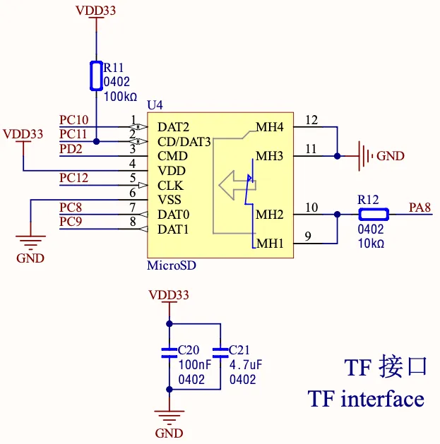
As you can see in the image above, the DATA pins from DAT0 to DAT3 are connected to pins PC8 to PC11. The SDIO_CLK is connected to PC12 and SDIO_CMD is connected to PD2.
There is also pin PA8, which needs to be set as input to the MCU. This pin will be used to detect the SD card.
Other than the SDIO connection, we also need to connect an USB-to-UART converter to view the serial logs on the console. Below is the image showing the connected between FT232 and the Dev Board.
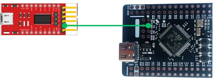
The TX Pin (PA9) from the MCU is connected to the RX pin of the Dev Board.
Note: Only the RX from FTDI is connected in this diagram, it’s used primarily for receiving data from the STM32.
STM32 CubeMX Configuration
I am using STM32F446RE for this project. We will start with the clock setup first.
Clock Configuration
Below is the image showing the clock configuration.
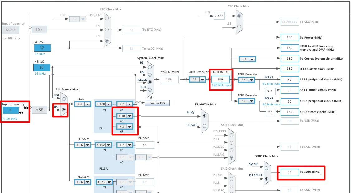
The system is clocked by the 8MHz HSE crystal and we will run it at maximum 180MHz. The SDIO clock is configured at 36MHz, you can increase it upto 48MHz here.
SDIO Configuration
Parameters
Below is the image showing SDIO configuration in 4 bit mode.
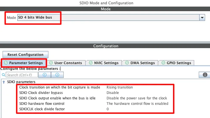
- The clock transition should be on the rising edge, which is the standard timing phase for SD card communication.
- SDIO clock divider bypass should be disabled so we can control clock frequency precisely.
- Disable the power saver feature for the SDIO clock to maintain stable, continuous operation.
- Enable the hardware flow control to help manage buffering and data flow under heavy loads.
The final parameter is the clock divider factor—this determines the actual SDIO bus speed. Below is the formula to calculate the SDIO Clock.
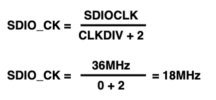
The SDIO clock should be set within 187 kilohertz and 24 megahertz during initialisation phases—and we have the clock within this specified range.
DMA Configuration
You can also enable the DMA for better performance. Below is the image showing the DMA configuration for the SDIO.
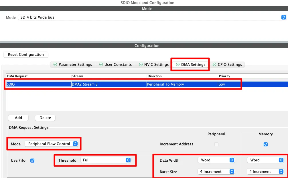
You can enable DMA for specific Transmit or Receive operations—or simply select SDIO to enable both channels automatically.
The mode should be set to Peripheral Flow Control, FIFO threshold set to Full, data width to Word, and burst size to 4 for optimal speed.
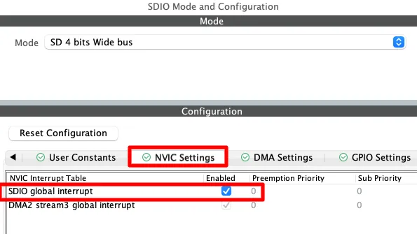
Go to the NVIC tab and make sure to enable the SDIO global interrupt—this is necessary, or else SDIO DMA writes won’t work.
Pin Configuration
Below is the image showing the pins configured in the cubeMX.
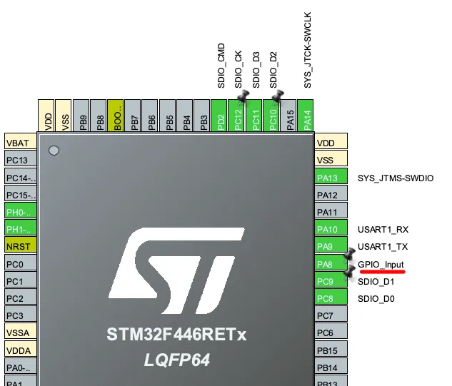
You can see in the image that the pins are configured according to the schematic of the STM32F446RE Dev board. I have configured the pin PA8 in the input mode as this pin is used to detect the SD card.
FATFS Configuration
Basic Defines
Below is the image showing the FATFS configuration for the SD card.
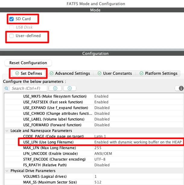
Enable the SD Card Mode in FATFS and make sure not to check the User-defined mode, instead we will use the BSP drivers for the SD card.
I am leaving everything to default except the use of Long Filenames. I have enabled the Long Filenames with dynamic buffer on the HEAP.
Advance Settings
Below is the image showing the Advance settings of FATFS.
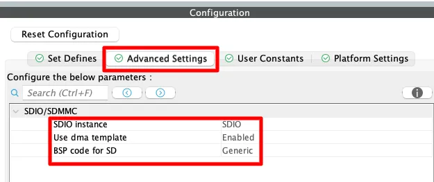
The SDIO instance is set to SDIO, DMA Template is Enabled and the BSP code is set to Generic.
Platform Settings
Below is the image showing the Platform Settings.
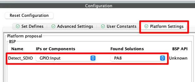
Here we will configure the Detect_SDIO pin to PA8. We configured this pin as input in the cubeMX, so that it can be used to detect the presence of the SD card.
Adding and Configuring the SDIO Library
After generating the project, we need to copy the library files to the src and inc folders. The final project after copying the files looks as shown below.
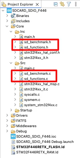
The sd_benchmark.c file is used for benchmarking the read and write speeds of the SD card. We also need to modify few things in this file.
/***************************************************************
 * 🔧 USER-MODIFIABLE SECTION
 * You are free to edit anything below this line
 ***************************************************************/

#define TEST_SIZE 512000*2 // 1MB Test File

/***************************************************************
 * 🚫 DO NOT MODIFY BELOW THIS LINE
 * Auto-generated/system-managed code. Changes may be lost.
***************************************************************/We can modify the TEST_SIZE to change the size of the test file which is copied and read from the SD card.
The sd_functions.c file contains all the user functions for the SD card operations. The file contains functions like mount, read, write, list, etc. We do not need to modify anything in this file.
The library uses the printf function to log the data to the serial console. We will define a custom write function to route the printf data via the UART. Make sure to define the correct UART instance in the write function.
int _write(int fd, unsigned char *buf, int len) {
  if (fd == 1 || fd == 2) {                     // stdout or stderr ?
    HAL_UART_Transmit(&huart1, buf, len, 999);  // Print to the UART
  }
  return len;
}The function MX_SDIO_SD_Init() inside the main file initialises the SDIO peripheral. Actually this function only configures the parameters, the actual initialisation takes place in the function BSP_SD_Init() which is inside the file bsp_driver_sd.c.
The SDIO can not initialize directly in the 4 bit mode. We need to first initialize it in 1 bit mode and then configure it to use the 4 bit wide bus. Below is the modified MX_SDIO_SD_Init() function.
static void MX_SDIO_SD_Init(void)
{
  /* USER CODE BEGIN SDIO_Init 1 */

  /* USER CODE END SDIO_Init 1 */
  hsd.Instance = SDIO;
  hsd.Init.ClockEdge = SDIO_CLOCK_EDGE_RISING;
  hsd.Init.ClockBypass = SDIO_CLOCK_BYPASS_DISABLE;
  hsd.Init.ClockPowerSave = SDIO_CLOCK_POWER_SAVE_DISABLE;
  hsd.Init.BusWide = SDIO_BUS_WIDE_4B;
  hsd.Init.HardwareFlowControl = SDIO_HARDWARE_FLOW_CONTROL_ENABLE;
  hsd.Init.ClockDiv = 0;
  /* USER CODE BEGIN SDIO_Init 2 */
  hsd.Init.BusWide = SDIO_BUS_WIDE_1B;  // add this
  /* USER CODE END SDIO_Init 2 */

}Since we have configured the SDIO in 4 bit mode, it will obviously initialise in that mode. Therefore we need to change the bus width to 1 bit. I did this by adding the line 14 in the initialisation code.
If you take a look at the BSP_SD_Init() function, you can see that after initialising the SDIO (HAL_SD_Init(&hsd);), the function enables wide operation by configuring the bus in 4 Bit mode.
STM32 HAL Code for SD Card via SDIO
Inclusions
We will start by including the header files first.
/* USER CODE BEGIN Includes */
#include "sd_functions.h"
#include "stdio.h"
#include "sd_benchmark.h"
/* USER CODE END Includes */The sd_functions contains all the user functions for SD card operations. The stdio will be used by the printf function and sd_benchmark will be used for benchmarking the SD card.
Definitions
We need to define some global variables.
uint8_t bufr[80];
UINT br;The bufr array will store the data read from a file on the SD card, which we will then print on the serial console. The variable br will store the number of bytes read from the file.
List Files
Let’s test the file listing first. I have already created some files and folders on the SD card and we will retrieve them on the console.
sd_mount();
sd_list_files();
sd_unmount();We will first mount the SD card, then retrieve all the files from it and finally unmount the card. Below is the image showing the output of this code.
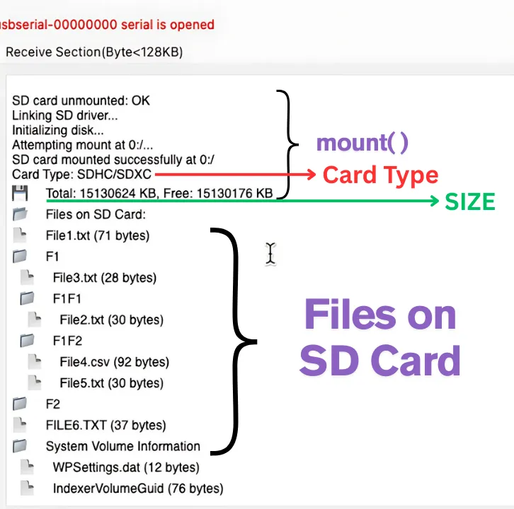
As you can see the mount was successful and the mount() function provides some details about the card like the card type (SDHC), its capacity (16GB) and Free space.
After mounting, it listed all the files and directories present on the card along with the file sizes.
Read File
Now we will read a file from the card and print its data on the serial console.
sd_mount();
sd_read_file("F1/F1F2/File5.TXT", bufr, 50, &br);
printf("DATA from File:::: %s\n\n",bufr);
sd_unmount();After mounting the card, we will read the data from the File5.txt. This file is present inside the folder F1F2, which itself is present in the folder F1.
After storing the data in the bufr array, we will print the array on the console and unmount the card.
Below is the image showing the output of this code.
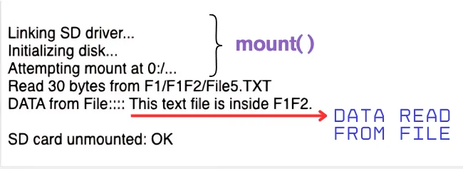
As you can see, after mounting the SD card, 30 bytes of data was read from the file5.txt. This data is then printed on the serial console.
Write File
Next we will test the write operation. We will create a new file and write some data into it.
sd_mount();
sd_write_file("FILE6.TXT", "This file is created by the cubeIDE\n");
sd_read_file("File6.txt", bufr, 80, &br);
printf("DATA from File:::: %s\n\n",bufr);
sd_list_files();
sd_unmount();After mounting the card, we will write the data into the File6.txt. This file is not present in the SD card, therefore the write operation will first create the file and then write the data into it.
After writing the data, we will read it back and print the data on the console.
We will also list the files to check if the fil6.txt is present on the SD card or not.
Below is the image showing the output of this code.
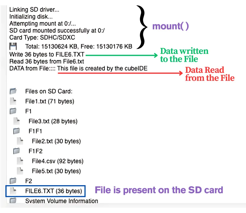
As you can see, after mounting SD Card, 36 bytes were written to File6.TXT. The data read from the file is same as what we wrote into it.
Also note that the list files shows the File6.TXT present on the root of the SD Card.
Read CSV File
Next we will read the CSV File. The library contains a function for the processing of CSV files. I already have a CSV file present in the SD Card. Below is the image showing the data inside the file.
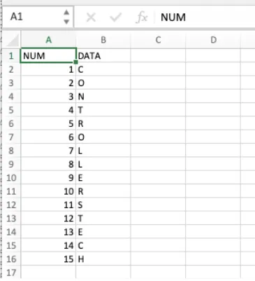
The CSV file has a total of 16 rows of data. We will read this file now.
#define max_records 20
CsvRecord myrecords[max_records];
int record_count = 0;
sd_mount();
sd_read_csv("F1/F1F2/File4.csv", myrecords, max_records, &record_count);
sd_unmount();- max_records is the maximum number of expected rows in the file.
- myrecords is the CsvRecord structure, which contains the 2 elements to store data of 2 columns.
- record_count is the actual number of rows read by the function.
After mounting the SD card, we will read data from the CSV file. The data will be stored in the myrecords structure.
Below is the image showing the output of this code.
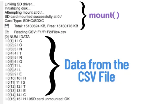
As you can see in the image, after mounting the card, the function read the data from the file correctly.
Append the File
Next we will append the data into an existing file. I will update the data to the File6.TXT created earlier.
sd_mount();
sd_append_file("File6.txt", "This is Appended Text\n");
sd_read_file("File6.txt", bufr, 80, &br);
printf("DATA from File:::: %s\n\n",bufr);
sd_unmount();After mounting the card, we will append the File6.TXT. This file should be already present in the SD card for the function to work.
We will then read the File6.TXT to get the complete data (Original Data + Appended data).
Below is the image showing the output of this code.
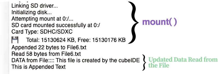
As you can see in the image above, the function appended 22 bytes to the file. Then we read 58 bytes from File6.txt. This file was originally 36 bytes and now 22 bytes are appended to it. The data read from the file is then printed on the console.
Benchmarks
The file sd_benchmark.c already contains the functions for benchmarking the SD card read and write capabilities. We just need to call the function sd_benchmark(); inside the main function.
Below is the image showing the test results.
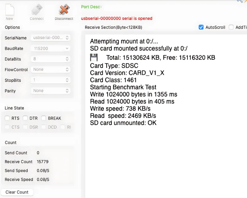
Here I am getting the write speed of 740KB/s and the read speed of 2.5MB/s in the SDIO 4Bit mode along with DMA.
Comparing Benchmarks
Below is the image showing the speed comparison between SPI and different modes in SDIO.
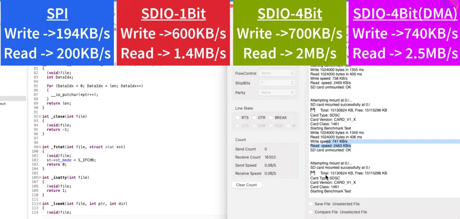
Using the SDIO mode drastically improves the SD card transfer speed. We can even see the improvements in using the 4Bit mode over the 1Bit Mode.
These comparisons are shown in detail in the video below.
Conclusion
In this tutorial, we covered how to interface an SD card with an STM32 microcontroller using the SDIO peripheral in 4-bit mode, along with DMA support for efficient data transfers. You learned how to configure the hardware connections, set up SDIO and DMA in STM32CubeMX, integrate FATFS, and perform common file operations such as mounting the card, reading and writing files, and handling data stored on the SD card. This forms a complete and practical foundation for working with external storage on STM32.
Using SDIO in 4-bit mode is especially useful for applications that require higher data throughput and better performance compared to SPI-based solutions. With DMA handling most of the data movement, the CPU remains free for other tasks, making this approach ideal for data logging, audio recording, image storage, configuration files, and other storage-intensive embedded applications. It also closely matches how SD cards are intended to be used, ensuring reliable and scalable performance as storage requirements grow.
If your project does not require high-speed transfers or if you prefer a simpler hardware setup, you can also interface an SD card using the SPI peripheral with DMA. That approach is covered in a separate tutorial and is a good alternative for simpler designs or MCUs without SDIO support. You can check out that tutorial here:
https://controllerstech.com/interface-sd-card-with-stm32-via-spi-dma/
Check out more STM32 Tutorials

STM32 Weather Station Web Server using Mongoose (Ethernet + BME280)
STM32 Microsecond Delay Using HAL Timer (delay_us Example)
STM32 Timers (Part 4): Input Capture Tutorial | Measure Frequency & Pulse Width
STM32 IoT with ESP8266 (Part 3): MQTT Connect and Publish messages
STM32 W5500 Ethernet Tutorial (Part 7): STM32 as MQTT Client

Riverdi STM32-U5 Embedded Display

I just wanted to let you know that the whole tutorial could be amazing and could answer all the questions I might have, but I refuse to read even one line of it just and only because the AI generated slop of a thumbnail you decided to put up here. At the moment I saw it, you lost the very last piece of my trust that you actually tried to run the project you present here on an actual hardware, because if you would, why would you generate the thumbnail using AI instead of taking a picture? Just look at it, the SD card is inserted backwards, the wires are malformed and what are even the large gold bricks supposed to be. At this point, I have no way of knowing if this would eventually work or whether is it just a vibecoded slop that you didn’t even try to run.
I have changed it now. Hope the AI vibes are reduced.
Attempting mount at 0:/…
Mount failed with code: 3
📂 Files on SD Card:
[ERR] Cannot open: 0:/
SD card unmounted: OK Why isn’t it working?
Make sure the SD card is formatted in FAT32.
Pate your static MX_SDIO_SD_Init() code (in main.c) here.
static void MX_SDIO_SD_Init(void)
{
  /* USER CODE BEGIN SDIO_Init 1 */

  /* USER CODE END SDIO_Init 1 */
  hsd.Instance = SDIO;
  hsd.Init.ClockEdge = SDIO_CLOCK_EDGE_RISING;
  hsd.Init.ClockBypass = SDIO_CLOCK_BYPASS_DISABLE;
  hsd.Init.ClockPowerSave = SDIO_CLOCK_POWER_SAVE_DISABLE;
  hsd.Init.BusWide = SDIO_BUS_WIDE_4B;
  hsd.Init.HardwareFlowControl = SDIO_HARDWARE_FLOW_CONTROL_ENABLE;
  hsd.Init.ClockDiv = 0;
  /* USER CODE BEGIN SDIO_Init 2 */
  hsd.Init.BusWide = SDIO_BUS_WIDE_1B;  // add this
  /* USER CODE END SDIO_Init 2 */

}
I am trying four cards: 2GB, 4GB, 16GB, and 32GB. The cards are formatted as FAT32.
In the SPI example, it works perfectly.
Put the SDIO contacts in the pull-up, it helped me with the same problem. You can also set SDIO_detect (PA8) to pull-down mode.