Last Updated: February 6, 2026
How to Port U8G2 Graphics Library to STM32
Discover how to port the U8G2 monochrome graphics library to STM32 with hardware SPI, I2C, and software SPI methods. This tutorial includes CubeMX setup, callbacks & demos. The project is available to download at the end of the post.
VIDEO TUTORIAL
You can check the video to see the complete explanation and working of this project.
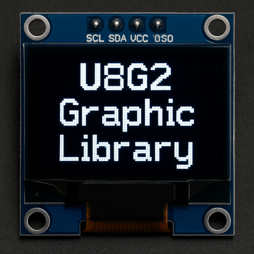
Introducing U8G2 Graphic Library
U8G2 (Universal 8-bit Graphics Library) is an open-source graphics library developed for embedded systems with monochrome displays such as OLED, LCD, and ePaper. It is widely used in projects involving microcontrollers like AVR, STM32, ESP32, and Arduino due to its ease of use, compact memory footprint, and compatibility with various display controllers (e.g., SSD1306, ST7920, SH1106).
The library provides a versatile set of functions to draw graphics, text, and user interface elements on small displays. U8G2 supports both hardware and software-based communication protocols like I2C and SPI, making it highly flexible across platforms and hardware configurations.
Here are some important features of the library:
- Wide Display Support: Supports over 100 display controllers and modules, including popular ones like SSD1306, ST7565, and ST7920.
- Multiple Communication Interfaces: Works with hardware/software I2C and SPI, providing flexibility in microcontroller pin usage.
- High-Level Drawing Functions: Offers built-in functions to render text, lines, circles, boxes, bitmaps, and other shapes with easy API calls.
- Font Management: Includes a large collection of pre-rendered fonts and allows selection of proportional and fixed-width fonts.
- Page Buffer Modes: Provides multiple rendering modes (full buffer, page buffer, or no buffer) to optimize memory usage on low-RAM systems.
You can get more details about the U8G2 Library from their GitHub page. They have an official porting guide, which we will follow in this tutorial.
According to the Porting Guide, there are only 2 set of things we need to modify while porting the library to any MCU.
- The “uC specific” GPIO and Delay callback.
- The u8x8 byte communication callback.
GPIO and Delay callback
GPIO and Delay callback takes care of all the messages regarding the GPIO and Delay.
The Delay messages might include the delay needed for the display (mostly in millis) or the delay needed to generate the SPI or I2C clocks (mostly in nano or micro) in case the software SPI or I2C is implemented.
The GPIO messages include the setting and resetting of the GPIO pins used for interfacing the display. These GPIO pins might include the data pins (D0 D1 D2 etc.. in parallel mode) or the control pins (CS RST DC in SPI mode).
Communication callback
Communication callback is used to handle the messages used during the communication with the display. These messages includes the transfer start, byte send, transfer end, etc.
In this tutorial we will cover different communication methods to interface different displays. We will see how to use the hardware SPI to interface SH1106 based 1.3″ Oled display, Hardware I2C to interface SSD1306 based 0.96″ Oled display and Software SPI to interface HX1230 display.
COMMON SETUP
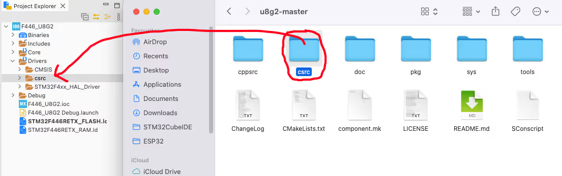
We need to copy the library files inside our project folder. To do that, first download the u8g2.zip from the GitHub Page.

Then extract the files. copy the csrc folder from the u8g2 and paste it inside the Drivers folder of the project.
Now open the project properties -> C/C++ Build -> Settings -> GCC Compiler -> Include Path and click add button to add the folder path here.
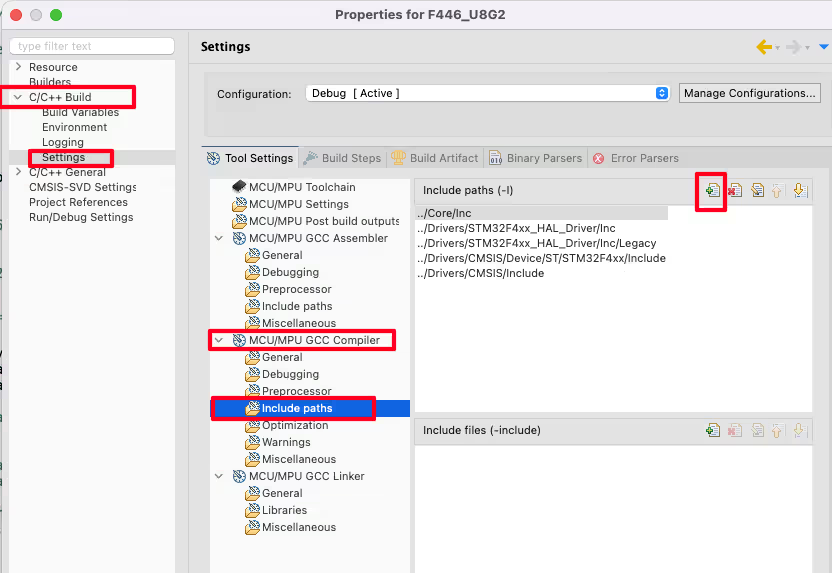
Now click on Workspace, browse the csrc folder inside the Drivers and click OK.
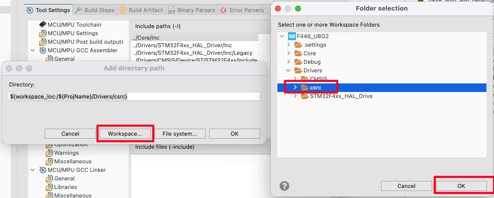
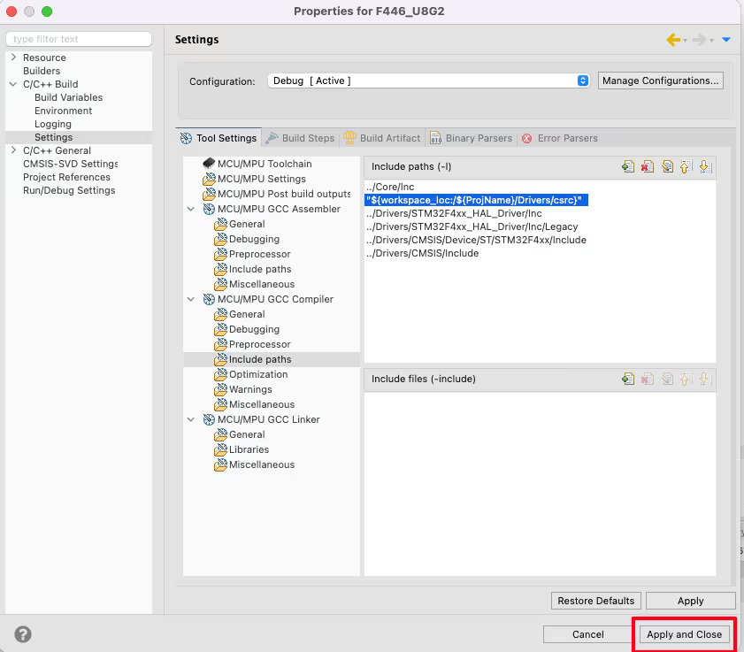
Finally click on Apply and Close to save this configuration.
1.3″ SH1106 SPI OLED DISPLAY
We will start with 1.3″ SH1106 based SPI Oled Display first. Below is the image showing the cubeMX Configuration needed to interface this display.
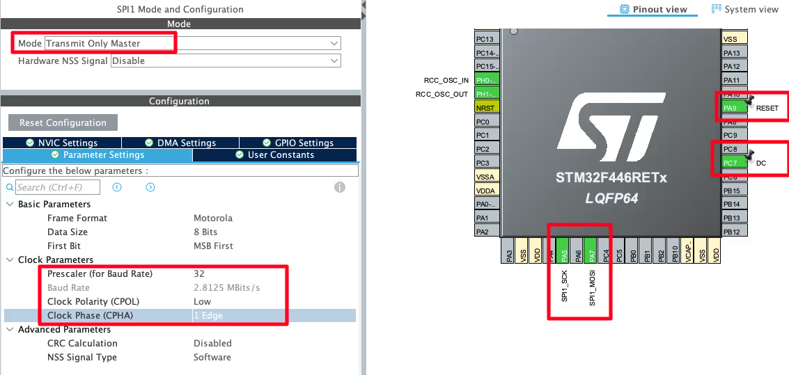
I have configured the SPI1 in the Transmit Only Master Mode. We do not need any data back from the display, so transmit only mode works fine.
The Baud rate should not be too high, so I have kept it around 3MBits/s. The CPOL is Low and CPHA is 1 Edge, basically the SPI Mode 0 is used.
Wiring Diagram
Below is the image showing the connection between the oled display and STM32.
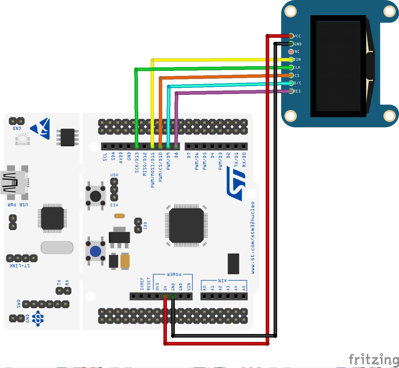
The pin Description is as follows:
| LCD Pin | Function | Connected to STM32 |
|---|---|---|
| VCC | Power Supply (5V) | 5V |
| GND | Ground | GND |
| SCK | SPI Clock | PA5 |
| MOSI (SDI) | SPI Data | PA7 |
| RESET | Reset Pin | PA9 |
| DC / RS | Data/Command Select | PC7 |
| CS | Chip Select | PB6 |
The Code
As I mentioned above, we need to setup the GPIO and Delay callback and the communication callback. Below is the GPIO and Delay callback function.
uint8_t u8x8_gpio_and_delay(u8x8_t *u8x8, uint8_t msg, uint8_t arg_int, void *arg_ptr)
{
	  switch(msg)
	  {
	  case U8X8_MSG_DELAY_MILLI:
		  HAL_Delay(arg_int);
		  break;
	  case U8X8_MSG_GPIO_CS:
		  HAL_GPIO_WritePin(CS_GPIO_Port, CS_Pin, arg_int);
		  break;
	  case U8X8_MSG_GPIO_DC:
		  HAL_GPIO_WritePin(DC_GPIO_Port, DC_Pin, arg_int);
		  break;
	  case U8X8_MSG_GPIO_RESET:
		  HAL_GPIO_WritePin(RESET_GPIO_Port, RESET_Pin, arg_int);
		  break;
	  }
	  return 1;
}The template for this callback is provided in the Porting Guide itself. Here we will only define the messages that we need for the display using hardware SPI communication.
- U8X8_MSG_DELAY_MILLI is called for the delay in milliseconds. Here we will simply call the HAL_Delay to provide the delay in ms. The parameter arg_int is the number of milliseconds.
- U8X8_MSG_GPIO_CS/DC/RESET are called for setting or resetting the respective pins. In this case, the parameter arg_int can be either 1 (set the pin) or 0 (Reset the pin). We will simply call the GPIO_WritePin function to set or reset the respective pin.
Now we will define the communication callback.
uint8_t u8x8_spi(u8x8_t *u8x8, uint8_t msg, uint8_t arg_int, void *arg_ptr)
{
	  switch(msg)
	  {
	  case U8X8_MSG_BYTE_SET_DC:
		  HAL_GPIO_WritePin(DC_GPIO_Port, DC_Pin, arg_int);
		  break;
	  case U8X8_MSG_BYTE_SEND:
		  HAL_SPI_Transmit(&hspi1, (uint8_t *)arg_ptr, arg_int, 1000);
		  break;
	  case U8X8_MSG_BYTE_START_TRANSFER:
		  HAL_GPIO_WritePin(CS_GPIO_Port, CS_Pin, GPIO_PIN_RESET);
		  break;
	  case U8X8_MSG_BYTE_END_TRANSFER:
		  HAL_GPIO_WritePin(CS_GPIO_Port, CS_Pin, GPIO_PIN_SET);
		  break;
	  }
	  return 1;
}The template for this callback is also defined in the Porting Guide. Below is the list explaining the messages used in this callback.
- U8X8_MSG_BYTE_SET_DC is called to set or reset the DC pin. In this case, the parameter arg_int can be either 1 (set the pin) or 0 (Reset the pin). We will simply call the GPIO_WritePin function to set or reset the DC pin.
- U8X8_MSG_BYTE_START_TRANSFER is used to start the data transfer to the SPI. We can use this message to enable the SPI Slave (Display) by resetting the CS pin.
- U8X8_MSG_BYTE_END_TRANSFER is used to end the data transfer via the SPI. We can use this message to disable the SPI Slave (Display) by setting the CS pin.
- U8X8_MSG_BYTE_SEND is used to send the data via the SPI. In this case, the parameter arg_ptr contains the data to be transmitted and arg_int is the number of data bytes. We can call the function HAL_SPI_Transmit to transmit the required amount of data bytes.
Below is the main function.
#include "u8g2.h"
u8g2_t myDisplay;
int main()
{
  ...
  u8g2_Setup_sh1106_128x64_noname_f(&myDisplay, U8G2_R0, u8x8_spi, u8x8_gpio_and_delay);  // init u8g2 structure
  u8g2_InitDisplay(&myDisplay); // send init sequence to the display, display is in sleep mode after this,
  u8g2_SetPowerSave(&myDisplay, 0); // wake up display

  u8g2_ClearDisplay(&myDisplay);
  u8g2_SetFont(&myDisplay, u8g2_font_ncenB14_tr);
  u8g2_DrawStr(&myDisplay, 0,15,"Hello world");
  u8g2_DrawCircle(&myDisplay, 60, 30, 10, U8G2_DRAW_ALL);
  u8g2_SendBuffer(&myDisplay);
  while (1) {}
}You can find the startup sequence for the library here in the docs. We need to first define the u8g2 structure, which I have defined as myDisplay.
Inside the main function, we will first set up the display. The function u8g2_Setup_sh1106_128x64_noname_f takes the following parameters:
- myDisplay is the u8g2 structure we just defined above.
- U8G2_R0 is the rotation. You can find more details about the rotation here.
- u8x8_spi is the Byte communication procedure. We have already defined this callback.
- u8x8_gpio_and_delay is the delay and GPIO procedure. We have also defined this callback.
The set up funciton u8g2_Setup_sh1106_128x64_noname_f has a “f” in the end. You will also find the set up functions with “1” and “2” in the end. These numbers basically means the <memory>: This is 1, 2 or f for one page, two page or full page mode. You can find more details about this in the video at the bottom of this post.
After setting up the display, we will initialise it and then wake it up by disabling the powersave mode.
Then I am printing a string (“Hello world”) on the top of the display and drawing a circle at the bottom of the display. You can check the reference manual to find more drawing functions you can use.
In the end we will send the buffer to the display, so that the buffer data can be printed on the display.
Result
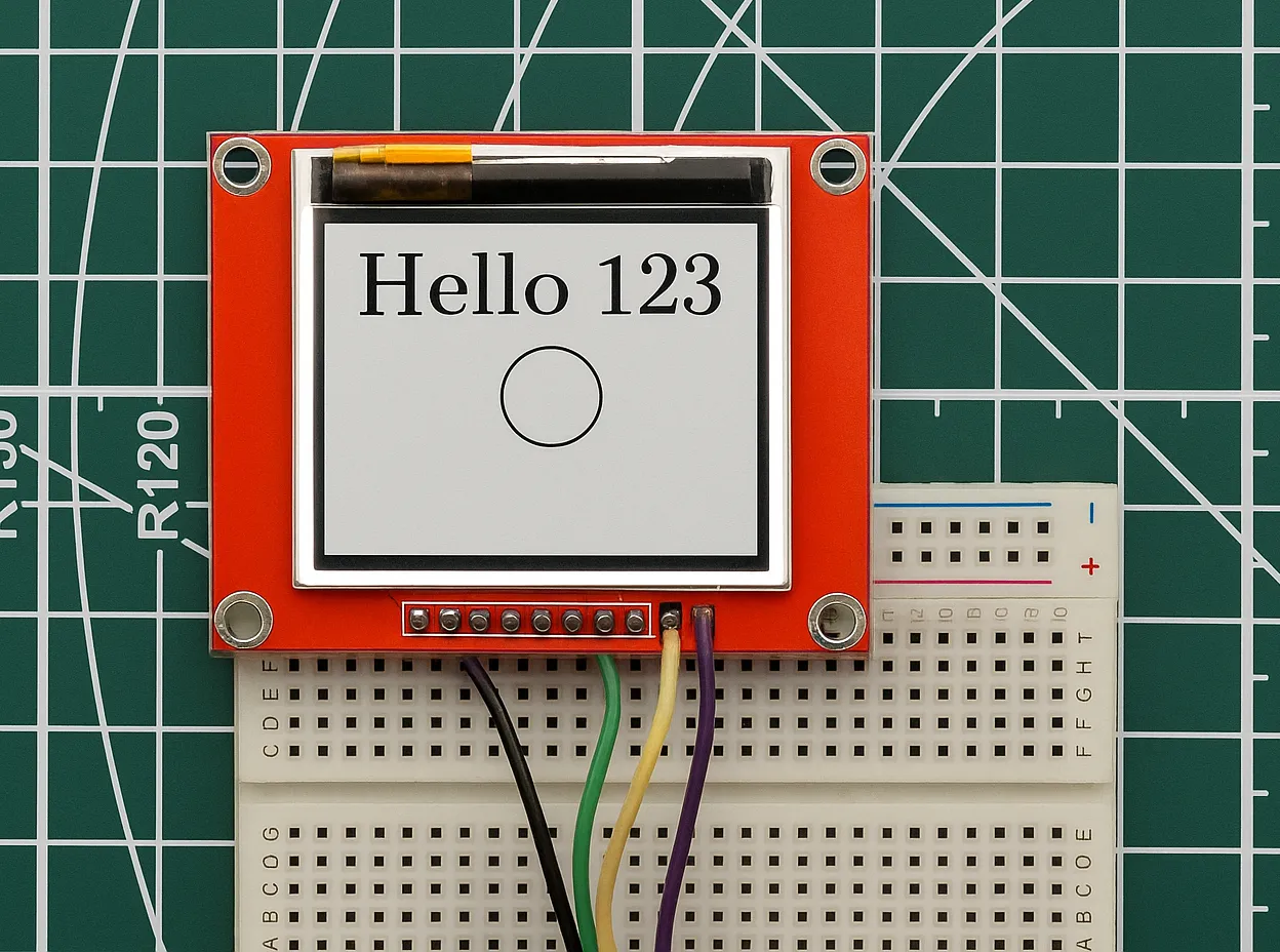
Below is the image showing the result of the above code.
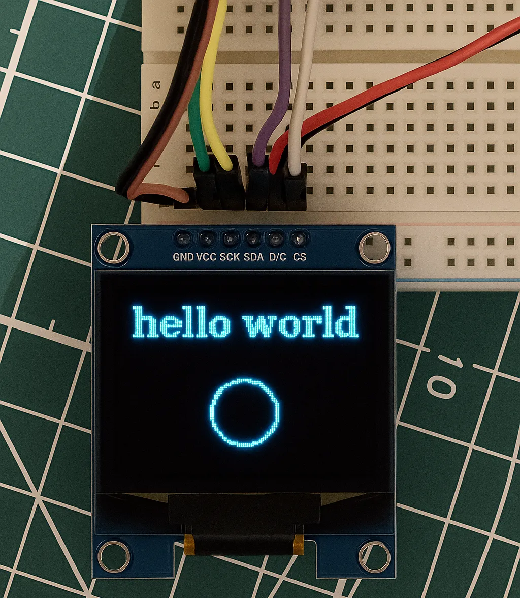
You can see the string “Hello World” is printed on the display. We also have a circle towards the lower side of the display.
The library works fine for the SH1106 oled display using Hardware SPI communication.
0.96″ SSD1306 I2C OLED DISPLAY
We will now see the 0.96″ SSD1306 based I2C Oled Display. Below is the image showing the cubeMX Configuration needed to interface this display.
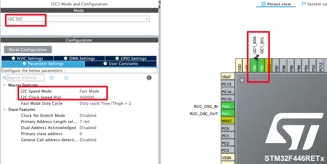
I have configured the I2C in fast Mode so that the I2C clock can be set to 400KHz. The SSD1306 oled display uses high speed I2C clock, therefore the fast mode is needed.
The pins PB8 and PB9 are configured as the SCL and SDA pins.
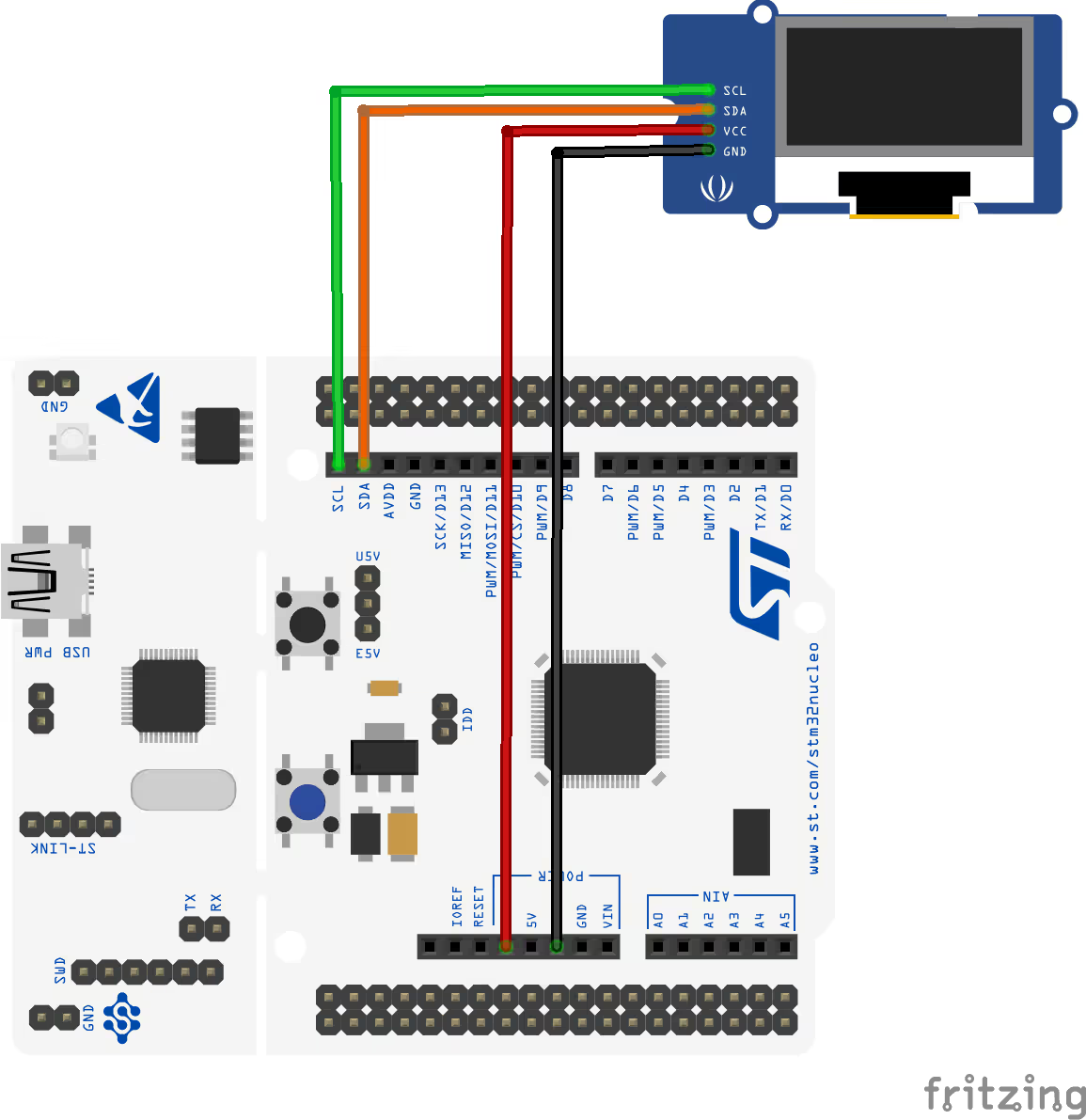
Wiring Diagram
Below is the image showing the connection between the oled display and F446.
The Code
We need to again setup the GPIO and Delay callback and the communication callback. Below is the GPIO and Delay callback function.
uint8_t u8x8_gpio_and_delay(u8x8_t *u8x8, uint8_t msg, uint8_t arg_int, void *arg_ptr)
{
	  switch(msg)
	  {
	  case U8X8_MSG_DELAY_MILLI:
		  HAL_Delay(arg_int);
		  break;
	  }
	  return 1;
}The template for this callback is provided in the Porting Guide itself. Here we will only define the messages that we need for the display using hardware SPI communication.
- U8X8_MSG_DELAY_MILLI is called for the delay in milliseconds. Here we will simply call the HAL_Delay to provide the delay in ms. The parameter arg_int is the number of milliseconds.
We are not using other pins (like CS, DC, RESET), so we do not need to define the messages for them.
Now we will define the communication callback.
uint8_t u8x8_i2c(u8x8_t *u8x8, uint8_t msg, uint8_t arg_int, void *arg_ptr)
{
  static uint8_t buffer[32];		/* u8g2/u8x8 will never send more than 32 bytes between START_TRANSFER and END_TRANSFER */
  static uint8_t buf_idx;
  uint8_t *data;

  switch(msg)
  {
    case U8X8_MSG_BYTE_SEND:
      data = (uint8_t *)arg_ptr;
      while( arg_int > 0 )
      {
	buffer[buf_idx++] = *data;
	data++;
	arg_int--;
      }
      break;
    case U8X8_MSG_BYTE_START_TRANSFER:
      buf_idx = 0;
      break;
    case U8X8_MSG_BYTE_END_TRANSFER:
    	HAL_I2C_Master_Transmit(&hi2c1, 0x78, buffer, buf_idx, 1000);
      break;
    default:
      return 0;
  }
  return 1;
}The template for this callback is also defined in the Porting Guide. It is a separate callback defined for the cases, where there is only one function used for the I2C data transfer.
Below is the list explaining the messages used in this callback.
- U8X8_MSG_BYTE_SEND is used to send the data. In this case, the parameter arg_ptr contains the data to be transmitted and arg_int is the number of data bytes. Here we will copy the data from the arg_ptr into the buffer.
- U8X8_MSG_BYTE_START_TRANSFER is used to start the data transfer to the SPI. Here we will simply reset the buffer index (buf_indx), so that new data can be copied from the beginning of the buffer.
- U8X8_MSG_BYTE_END_TRANSFER is used to end the data transfer via the SPI. Here we will actually transfer the data via the I2C. We will call the function HAL_I2C_Master_Transmit to transmit the data to the display. 0x78 is the slave address of SSD1306, buffer is the data we want to transmit and buf_indx is the number of data bytes.
Below is the main function.
#include "u8g2.h"
u8g2_t myDisplay;
int main()
{
  ...
  u8g2_Setup_ssd1306_i2c_128x64_noname_f(&myDisplay, U8G2_R0, u8x8_i2c, u8x8_gpio_and_delay);
  u8g2_InitDisplay(&myDisplay); // send init sequence to the display, display is in sleep mode after this,
  u8g2_SetPowerSave(&myDisplay, 0); // wake up display

  u8g2_ClearDisplay(&myDisplay);
  u8g2_SetFont(&myDisplay, u8g2_font_ncenB14_tr);
  u8g2_DrawStr(&myDisplay, 0,15,"Hello world");
  u8g2_DrawCircle(&myDisplay, 60, 30, 10, U8G2_DRAW_ALL);
  u8g2_SendBuffer(&myDisplay);
  while (1) {}
}You can find the startup sequence for the library here in the docs. We need to first define the u8g2 structure, which I have defined as myDisplay.
Inside the main function, we will first set up the display. The function u8g2_Setup_ssd1306_i2c_128x64_noname_f takes the following parameters:
- myDisplay is the u8g2 structure we just defined above.
- U8G2_R0 is the rotation. You can find more details about the rotation here.
- u8x8_i2c is the Byte communication procedure. We have already defined this callback.
- u8x8_gpio_and_delay is the delay and GPIO procedure. We have also defined this callback.
After setting up the display, we will initialise it and then wake it up by disabling the powersave mode.
Then I am printing a string (“Hello world”) on the top of the display and drawing a circle at the bottom of the display. You can check the reference manual to find more drawing functions you can use.
In the end we will send the buffer to the display, so that the buffer data can be printed on the display.
Result
Below is the image showing the result of the above code.
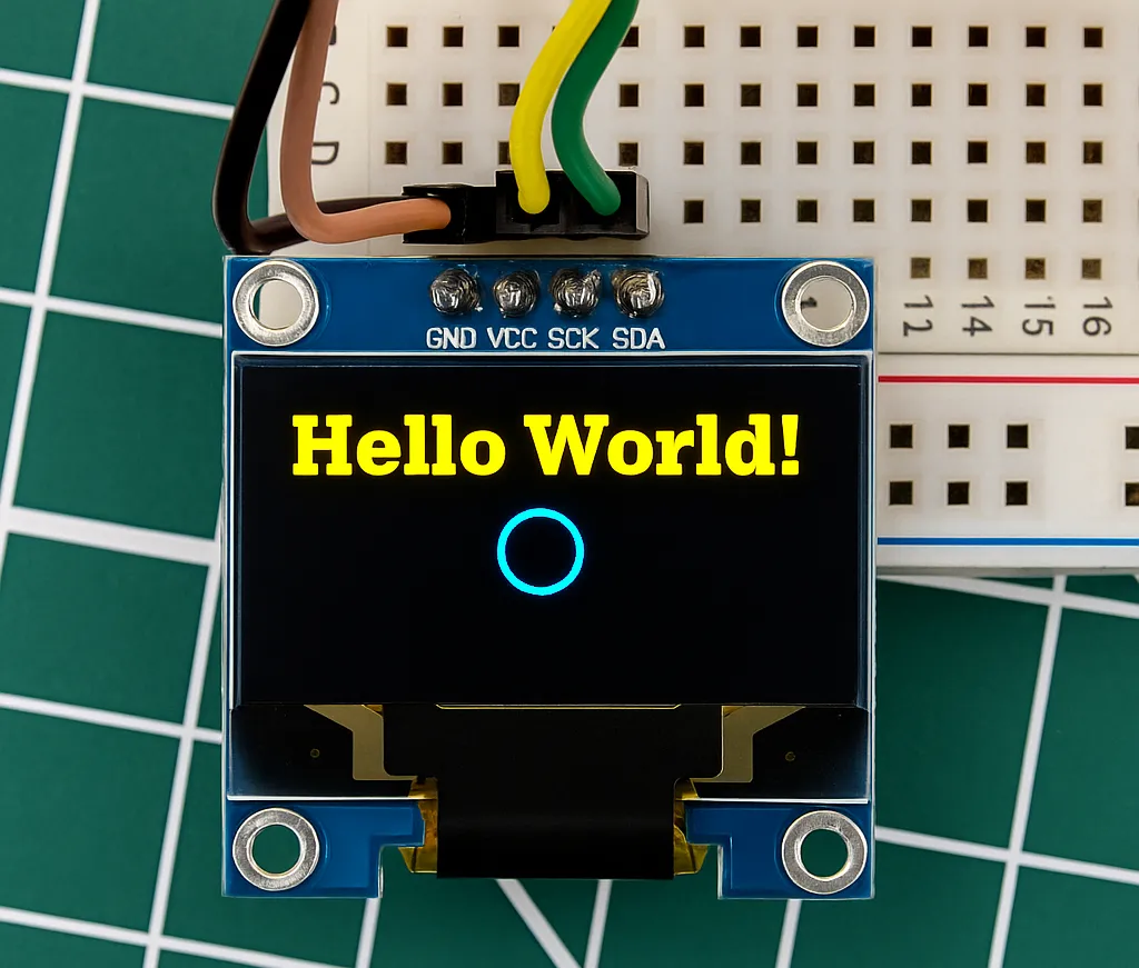
You can see the string “Hello World” is printed on the display. We also have a circle towards the lower side of the display.
The library works fine for the SSD1306 oled display using Hardware I2C communication.
HX1230 GRAPHIC LCD DISPLAY
We will now see an example using the HX1230 based Graphic LCD Display. This display is a little different than the ones we used above. Below is the image showing the instruction format for the display.
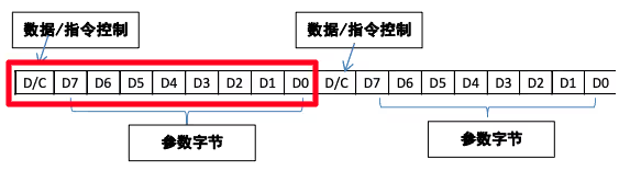
As shown in the image above, the HX1230 uses 9 bits (1D/C + 8 Data) instruction format. The STM32 SPI is capable of either 8bit or 16bit data transmission. We can use 9 bits with the hardware SPI, but we have to write a lot of code to keep track of the number of bits transmitted and the number of bits remaining.
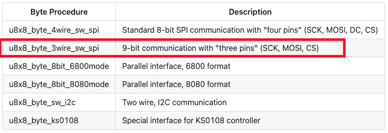
Instead we can use the software SPI and use the predefined communication callbacks to perform 9 bit transmission. This is shown in the image below.
Now that we are going to use the software SPI, we need to configure the clock and data pins as output in the cubeMX.
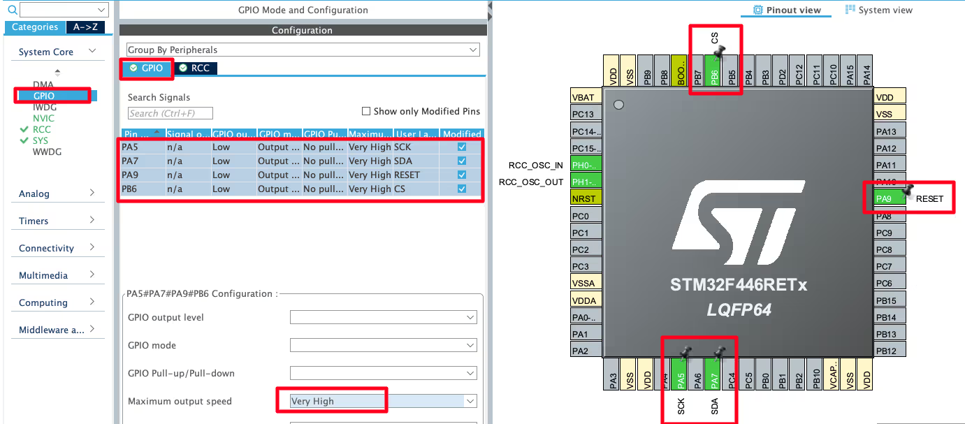
I have configured the pin PA5 (SCK) , PA7 (SDA) , PA9 (RESET), PC7 (DC) and PB6 (CS) as output.
Go to the GPIO Configuration and set the speed for these pins as very High.
WIRING DIAGRAM
Below is the image showing the connection between the display and the nucleo F446.
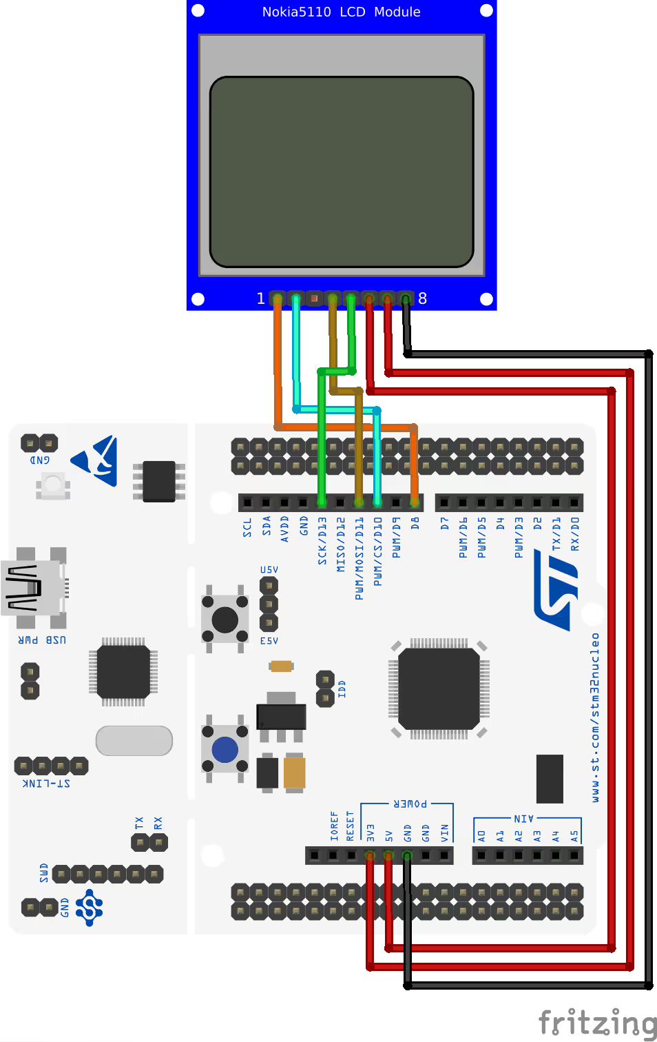
The connection is same as we do in case of SPI. The image shows the connection of the Nokia 5110 LCD, but it is same in case of HX1230 also. The only difference is the DC pin is absent in HX1230, hence it is left un connected in the connection diagram.
The Code
We will setup the GPIO and Delay callback function.
uint8_t u8x8_gpio_and_delay(u8x8_t *u8x8, uint8_t msg, uint8_t arg_int, void *arg_ptr)
{
	  switch(msg)
	  {
	    case U8X8_MSG_DELAY_NANO:			// delay arg_int * 1 nano second
	    	asm("NOP");
	      break;
	    case U8X8_MSG_DELAY_100NANO:		// delay arg_int * 100 nano seconds
	    	for (int i=0; i<30; i++)asm("NOP");
	      break;
	  case U8X8_MSG_DELAY_MILLI:
		  HAL_Delay(arg_int);
		  break;
	  case U8X8_MSG_GPIO_SPI_DATA:
		  HAL_GPIO_WritePin(SDA_GPIO_Port, SDA_Pin, arg_int);
	        break;
	  case U8X8_MSG_GPIO_SPI_CLOCK:
		  HAL_GPIO_WritePin(SCK_GPIO_Port, SCK_Pin, arg_int);
	        break;
	  case U8X8_MSG_GPIO_CS:
		  HAL_GPIO_WritePin(CS_GPIO_Port, CS_Pin, arg_int);
		  break;
	  case U8X8_MSG_GPIO_RESET:
		  HAL_GPIO_WritePin(RESET_GPIO_Port, RESET_Pin, arg_int);
		  break;
	  }
	  return 1;
}The template for this callback is provided in the Porting Guide itself. Here we will only define the messages that we need for the display using software SPI communication.
- U8X8_MSG_DELAY_NANO is used to generate the delay in nanoseconds. It is needed to generate the SPI clock. We exactly do not need a nanosecond, but is should be small enough to generate a fast clock. I am simply performing “No operation” here.
- U8X8_MSG_DELAY_100NANO is again can be used to generate the clock. Here also I am performing a “No Operation” but in a for loop.
- U8X8_MSG_DELAY_MILLI is called for the delay in milliseconds. Here we will simply call the HAL_Delay to provide the delay in ms. The parameter arg_int is the number of milliseconds.
- U8X8_MSG_GPIO_SPI_DATA & U8X8_MSG_GPIO_SPI_CLOCK are called to set or reset the Data and Clock pins. This is done to generate a SPI transaction. In this case, the parameter arg_int can be either 1 (set the pin) or 0 (Reset the pin). We will simply call the GPIO_WritePin function to set or reset the respective pin.
- U8X8_MSG_GPIO_CS / RESET are called for setting or resetting the respective pins. In this case, the parameter arg_int can be either 1 (set the pin) or 0 (Reset the pin). We will simply call the GPIO_WritePin function to set or reset the respective pin.
Below is the main function.
#include "u8g2.h"
u8g2_t myDisplay;
int main()
{
  ...
  u8g2_Setup_hx1230_96x68_f(&myDisplay, U8G2_R0, u8x8_byte_3wire_sw_spi, u8x8_gpio_and_delay);
  u8g2_InitDisplay(&myDisplay); // send init sequence to the display, display is in sleep mode after this,
  u8g2_SetPowerSave(&myDisplay, 0); // wake up display

  u8g2_ClearDisplay(&myDisplay);
  u8g2_SetFont(&myDisplay, u8g2_font_ncenB14_tr);
  u8g2_DrawStr(&myDisplay, 0,15,"Hello world");
  u8g2_DrawCircle(&myDisplay, 60, 30, 10, U8G2_DRAW_ALL);
  u8g2_SendBuffer(&myDisplay);
  while (1) {}
}You can find the startup sequence for the library here in the docs. We need to first define the u8g2 structure, which I have defined as myDisplay.
Inside the main function, we will first set up the display. The function u8g2_Setup_hx1230_96x68_f takes the following parameters:
- myDisplay is the u8g2 structure we just defined above.
- U8G2_R0 is the rotation. You can find more details about the rotation here.
- u8x8_byte_3wire_sw_spi is the Byte communication procedure. We are using the software SPI, therefore we will use a predefined callback here.
- u8x8_gpio_and_delay is the delay and GPIO procedure. We have also defined this callback.
After setting up the display, we will initialise it and then wake it up by disabling the powersave mode.
Then I am printing a string (“Hello world”) on the top of the display and drawing a circle at the bottom of the display. You can check the reference manual to find more drawing functions you can use.
In the end we will send the buffer to the display, so that the buffer data can be printed on the display.
Result
Below is the image showing the result of the above code.
You can see the string “Hello World” is printed on the display. We also have a circle towards the lower side of the display.
The library works fine for the HX1230 LCD display using software SPI communication.
Guten Morgen Ich Ärgere mich mit einem SH1106 / I2c rum
welche Startsec benötigt der?
Die Beispiele Funktionieren alle….
I just used your ported u8g2 library code for SSD1306 0.9in OLED with my STM32F411CEU6 black pill module… It worked perfect!!! Thank you so much ControllersTech for such a clean work!!!.
I even tried changing the font to my fav fixed width font “u8g2_font_unifont_tr” and it worked!
If any one needs help for using the above code in STM32, you can contact me @+91 9491685146