Last Updated: March 23, 2026
GP2Y0A41SK0F STM32 ADC Distance Measurement Guide
In this tutorial you will learn how to interface the GP2Y0A41SK0F IR distance sensor with STM32 using ADC. The tutorial includes circuit diagram, code example, and distance measurement explanation from the datasheet of the sensor.
VIDEO TUTORIAL
You can check the video to see the complete explanation and working of this project.
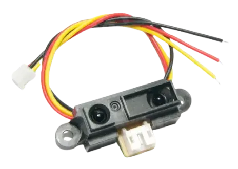
Introducing GP2Y0A41SK0F IR-SHARP sensor
The GP2Y0A41SK0F is a sensor used to measure distance. It combines a position-sensitive detector (PSD), an infrared LED, and a signal processing circuit in one unit. It uses the triangulation method, which helps it measure distance accurately even if the object’s surface, temperature, or usage time changes. The sensor gives an output voltage based on how far the object is, so it can also work as a proximity sensor.
The sensor has the following Features:
- Distance measuring sensor includes PSD, infrared LED, and signal processing circuit
- Short measuring cycle: 16.5 ms
- Measuring range: 4 to 30 cm
- Analog output type
WIRING DIAGRAM
The sensor works with ADC, so it only need 1 pin to connect with the MCU. Below is the image showing the connection between GP2Y0A41SK0F and STM32F103C8T6.
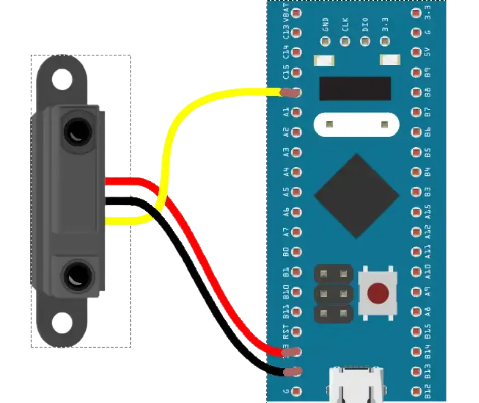
The table below describes the pin connection.
| Sensor Pin | Function | Connected to STM32 |
|---|---|---|
| VCC | Power (3.3V) | 3.3V |
| GND | Ground | GND |
| SIG | Analog Output | PA0 (ADC1_CH0) |
CUBEMX CONFIGURATION
Clock Configuration
Below is the image showing the clock configuration for the project.
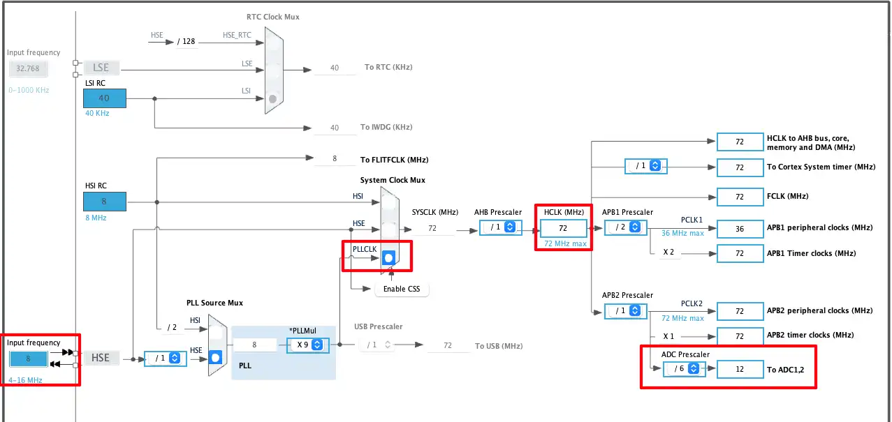
The STM32F103C8T6 board has 8Mhz crystal on it. We will use this External HSE to run the system at maximum 72Mhz. Also note that the ADC clock is set to 12Mhz. The STM32F103 ADC can run at a maximum clock of 14Mhz, so make sure the clock is configured at a frequency not higher than this.
ADC Configuration
Next we will configure the ADC.
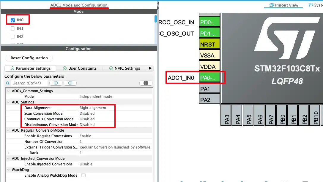
Enable the ADC1 CHANNEL0. The ADC parameters are configured in the default mode. We will read the single channel ADC value in the blocking mode, therefore we do not need to modify anything here. You can read more about the ADC modes in the STM32 ADC Series.
The pin PA0 automatically configured as the ADC1_IN0 pin. This is where the sensor’s signal pin is connected.
THE CODE
The measuring function
We will first write a separate function to read the ADC value in the blocking mode. This ADC value will be converted to the distance using the information from the datasheet of the sensor.
float distance;

void measure_dist (void)
{
	HAL_ADC_Start(&hadc1);
	HAL_ADC_PollForConversion(&hadc1, 10);
	uint16_t ADC_VAL = HAL_ADC_GetValue(&hadc1);
	HAL_ADC_Stop(&hadc1);

	float Vo = (float)ADC_VAL*3.3/4095.0;
	distance = (13.0/Vo) - 0.42;
}The function measure_dist will do all the reading and calculation for the distance. Let’s understand the code in detail.
Reading ADC
First of all we will read the ADC value in the blocking mode. The process is very simple. START the ADC, POLL for the conversion to complete, READ the ADC value and STOP the ADC. The STM32F103 has 12bit ADC by default, therefore we will store the ADC value in a 16bit ADC_VAL variable.
	HAL_ADC_Start(&hadc1);
	HAL_ADC_PollForConversion(&hadc1, 10);
	uint16_t ADC_VAL = HAL_ADC_GetValue(&hadc1);
HAL_ADC_Stop(&hadc1);Convert the ADC value to distance
After reading the ADC value, it needs to be converted into distance. However, the sensor’s datasheet does not provide a direct formula linking output voltage to distance. Instead, it includes two graphs (on pages 4 and 5) that illustrate this relationship. For this project, we will refer to the graph on Page 5, as it shows a nearly linear relationship over most of the sensor’s range.
Below is the image showing the reference points taken on the graph.
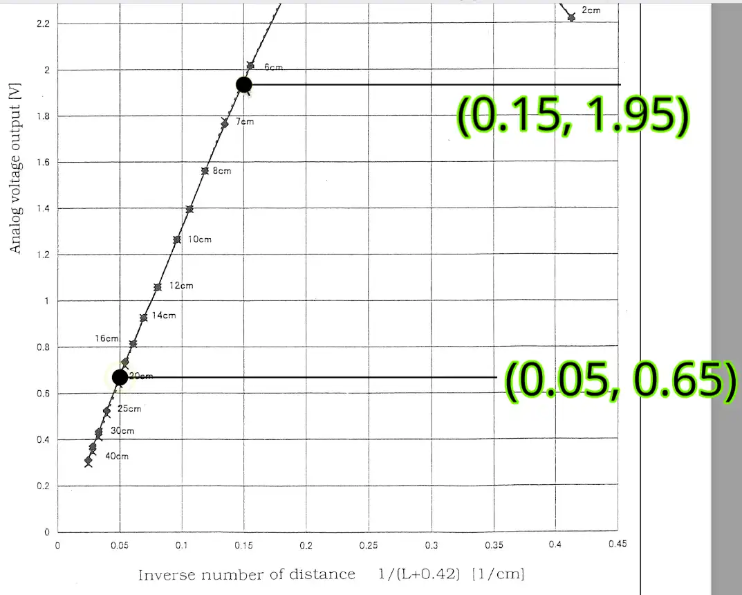
Assuming this is the graph of a straight line, using these 2 points for the reference, the slope of this line will be 13, Slope (m) = (y₂ − y₁) / (x₂ − x₁). If you further use one of these points to calculate the Y intercept, it will come out as 0. Therefore the equation of this line will be y = 13x.
Here the x axis is the inverse of the distance 1/(L+0.42). Therefore the equation of the above graph will be V = 13*(1/(L+0.42)). Rearranging this equation to make L as the subject will result in L = (13/V)-0.42.
	float Vo = (float)ADC_VAL*3.3/4095.0;
distance = (13.0/Vo) - 0.42;We will first convert the ADC value to the voltage. The default reference voltage in STM32 is 3.3V, hence it is used to convert the 12bit ADC value to the voltage ranging from 0 to 3.3V. Then we will use this voltage value to find the distance as per the formula mentioned above.
The Main Function
Inside the main function, we will first calibrate the ADC (if available). Finally call the measure function in the while loop every 500ms.
int main()
{
  .....
  .....
  HAL_ADCEx_Calibration_Start(&hadc1);
  while (1)
  {
	  measure_dist();
	  HAL_Delay(500);
  }
}If you need, you can connect a LCD to see the measured distance.To keep the project simple, I am going to view it in the debugger.
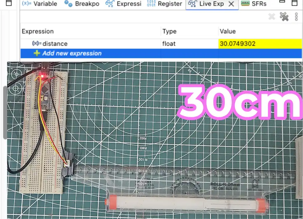
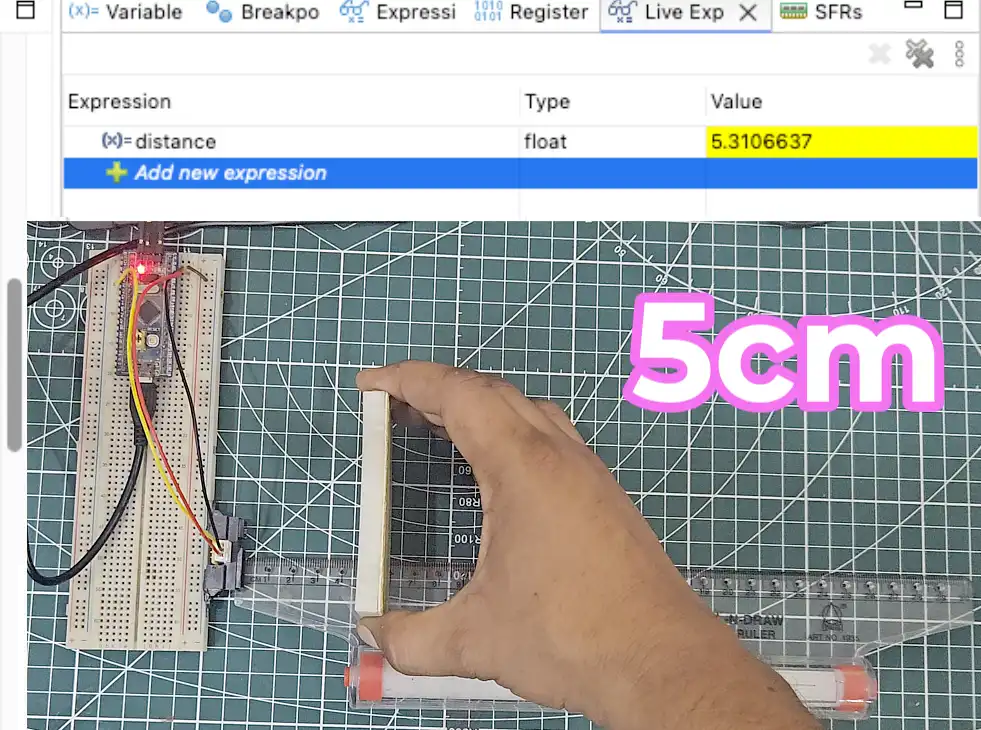
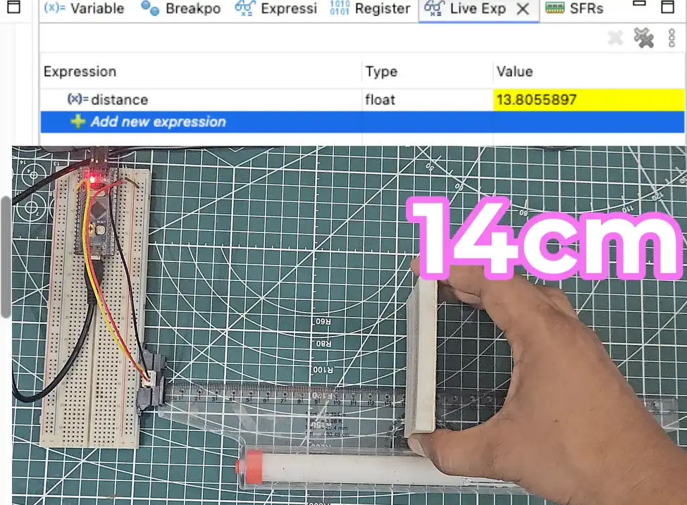
RESULT
Below are the images showing the distance of the object in the debugger window. The object position on the scale is not clear, hence I have mentioned it in the image itself.
5cm Away from GP2Y0A41SK0F
14cm Away from GP2Y0A41SK0F
30cm Away from GP2Y0A41SK0F