Incremental ENCODER and STM32
This tutorial will cover How to use Incremental Encoder with STM32. Also we will see how can we control the angle in Servo motor.
I have already covered the Servo motor earlier, and you can take a look at that article first, https://controllerstech.com/servo-motor-with-stm32/
As I have already mentioned in that article, even though the standard servo motors operate between 1ms to 2ms Pulse width, some motors (even mine) works between 0.5ms to 2.5ms. For 0.5ms, the angle of rotation remains 0, and for 2.5ms the angle changes to 180.
We will talk about servo in the later part of this tutorial, let’s see the ENCODER first.
You can use the TIMER in the ENCODER mode to interface the encoder. I have also added the speed feature (experimental). The code can be accessed at https://github.com/controllerstech/STM32/tree/master/TIMER%20ENCODER%20MODE
VIDEO TUTORIAL
You can check the video to see the complete explanation and working of this project.
Check out the Video Below
Incremental ENCODER
An incremental encoder is a linear or rotary electromechanical device that has two output signals, A and B, which issue pulses when the device is moved. Together, the A and B signals indicate both the occurrence of and direction of movement.
Unlike an absolute encoder, an incremental encoder does not indicate absolute position. It only reports changes in position, and for each reported position change, the direction of movement.
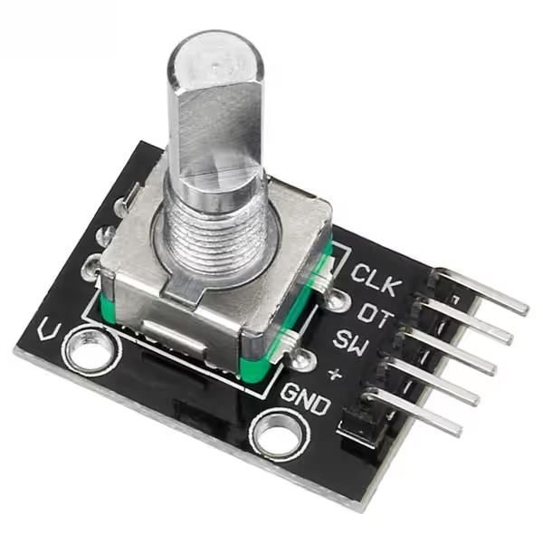
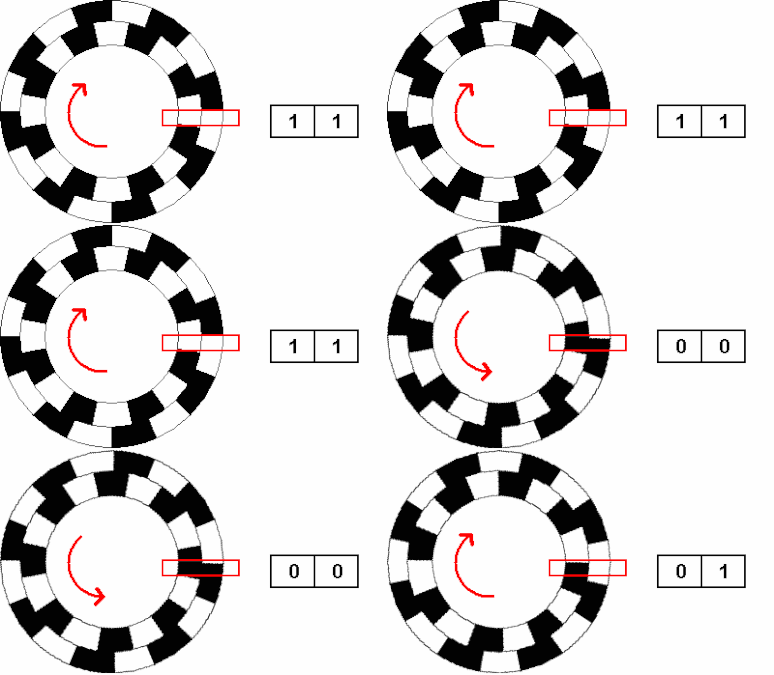
In the above picture, the CLK and DT are the two output signals that I was talking about. These will be considered as the A and B signals from the Encoder. To explain it more clearly, below is the GIF from the Wikipedia page
As you can see above, at some point both the signals are HIGH.
- Now when we move the shaft in Clockwise Direction, the A goes to LOW and after some time, Pin B will go to LOW.
- And when the shaft is moved in the CCK Direction, the Pin B will go LOW first and then Pin A.
This is our queue. We will be continuously checking for these pins, and based on which goes LOW first, we will make a decision about whether the movement was CK or CCK.
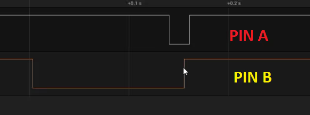
The picture above is the result of the CK movement. Here we can see that first the Pin A goes to LOW and later the pin B.
Similarly the picture below shows the CCK movement of the shaft
As expected during the CCK movement, the Pin B goes Low first, and then the pin A.
Some Insight into the code
if (HAL_GPIO_ReadPin(GPIOA, GPIO_PIN_1) == GPIO_PIN_RESET)  // If the OUTA is RESET
{
 if (HAL_GPIO_ReadPin(GPIOA, GPIO_PIN_2) == GPIO_PIN_RESET)  // If OUTB is also reset... CCK
 {
  while (HAL_GPIO_ReadPin(GPIOA, GPIO_PIN_2) == GPIO_PIN_RESET){};  // wait for the OUTB to go high
  counter--;
  while (HAL_GPIO_ReadPin(GPIOA, GPIO_PIN_1) == GPIO_PIN_RESET){};  // wait for the OUTA to go high
  HAL_Delay (10);  // wait for some more time
 }

 else if (HAL_GPIO_ReadPin(GPIOA, GPIO_PIN_2) == GPIO_PIN_SET)  // If OUTB is also set
 {
  while (HAL_GPIO_ReadPin(GPIOA, GPIO_PIN_2) == GPIO_PIN_SET){};  // wait for the OUTB to go LOW.. CK
  counter++;
  while (HAL_GPIO_ReadPin(GPIOA, GPIO_PIN_1) == GPIO_PIN_RESET){};  // wait for the OUTA to go high
  while (HAL_GPIO_ReadPin(GPIOA, GPIO_PIN_2) == GPIO_PIN_RESET){};  // wait for the OUTB to go high
  HAL_Delay (10);  // wait for some more time
 }

 if (counter<0) counter = 0;
 if (counter>180) counter =180;
}- We will first check if the Pin A is low, and then check for Pin B
- If the Pin A goes to LOW, and at that point if Pin B was already LOW, that means Pin B must have gone low before Pin A, and this would be a CCK movement.
- We will decrease the counter here
- If the Pin goes to LOW, and at that point if Pin B was HIGH, that means Pin A have gone LOW before Pin B, and this would be a CK movement.
- We will increase the counter here.
- I am limiting the counter between 0 to 180, so that it would be easier to deal with Servo motor.
Servo Motor
Now we will integrate the Encoder with the Servo Motor.
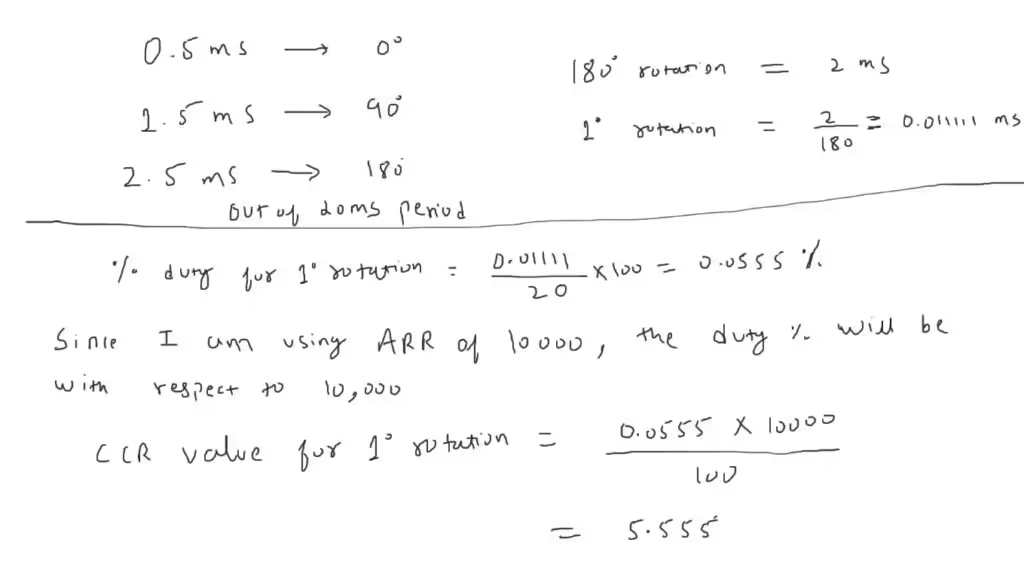
As I already mentioned before, the servo I have, works between 0.5ms to 2.5ms Pulse width. This means the servo covers the angle of 180 degrees in 2ms Pulse difference.
We can use this to calculate the pulse width required for each 1 degree increment in the angle. I have tried to explain it in the picture below
The Timer clock was originally running at 72 MHz, and in order to supply a pulse of 20ms Period, we need to bring this clock down to 50 Hz.
This can be done by using Prescaler along with ARR values.
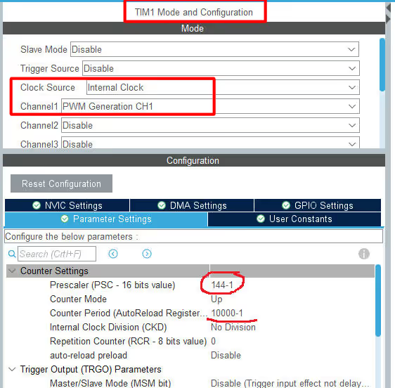
Using the Prescalar of 144 and the ARR of 10000 will bring the timer clock to 50 Hz. 72000000/(144×10000) = 50.
Based on the counter value from the Encoder, we can rotate the servo by a definite angle.
PWMVal = counter*55/10;

htim1.Instance->CCR1 = 250 + PWMVal;- Here we will multiply the counter value (angle) by 5.5 (value for 1 degree rotation).
- 250 is the CCR equivalent of 0.5ms. We need to add this with every value, because it’s the value for 0 degrees.
- For example, if the angle is 90, the PWMVal will be approximately 500, and that will make the CCR = 750
- This 750/10000 is same as 1.5/20.
STM32 Timer Tutorial Series
STM32 TIMERS #2. How to Measure PWM Input
STM32 Timer #4: Input Capture Tutorial | Measure Frequency & Pulse Width
STM32 TIMERS #5. Timer synchronization || Slave Trigger mode
STM32 TIMERS #6. Timer synchronization || Generate 3 Phase PWM
STM32 TIMERS #7. Timer synchronization || Slave Reset mode
STM32 TIMERS #8. Make 48 bit Counter by Cascading Timers
STM32 Timers #9. One Pulse Mode
Info
You can help with the development by DONATING Below.
To download the project, click the DOWNLOAD button.

