Home ▸ STM32 Tutorials ▸ STM32 CAN ▸
Updated On: April 30, 2026
STM32 CAN Bus Communication in Normal Mode: CubeMX Setup & HAL Code
CAN bus is the standard for reliable multi-node communication in embedded systems — used in automotive ECUs, industrial controllers, motor drivers, and robotic systems. Setting it up for the first time on STM32 can feel daunting, but the HAL library handles most of the low-level protocol work, leaving you to focus on configuration and application logic.
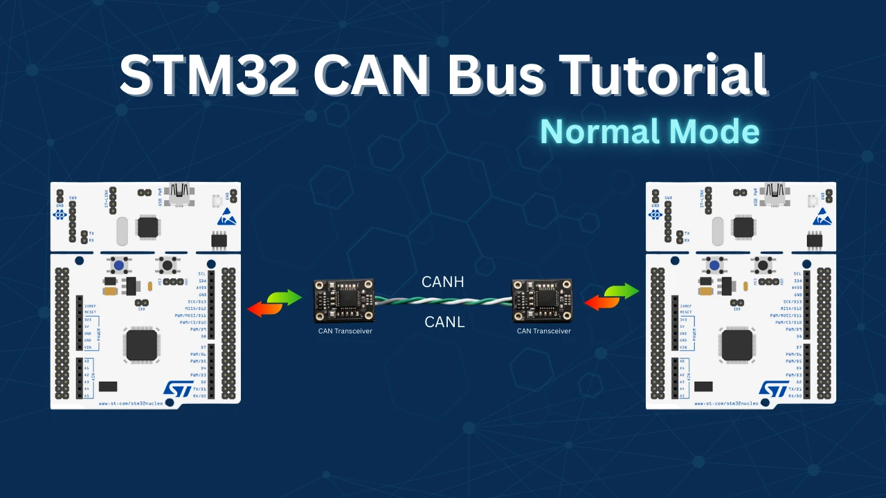
In this tutorial you will set up STM32 CAN bus communication in Normal Mode from scratch. We connect two STM32 boards through MCP2551 CAN transceivers, configure CAN1 at 500 kbps in CubeMX, write HAL code to build and transmit a CAN data frame, configure hardware message filters using filter banks, and receive messages through the RX FIFO0 interrupt and callback — no polling required. The complete project is available to download at the bottom of the page.
I’ve also covered several other tutorials on the STM32 CAN/FDCAN peripheral. You can explore them below:
STM32 CAN Bus: How It Works
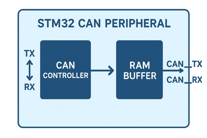
The CAN (Controller Area Network) peripheral in STM32 microcontrollers makes it easy to exchange data between multiple devices over a single bus. Originally built for cars, CAN is now used in industrial machines, robots, and many other embedded systems because it’s reliable, fast, and fault-tolerant.
In STM32, the CAN peripheral handles the low-level protocol mechanics, including message framing, filtering, error handling, and arbitration. It supports both standard (11-bit) and extended (29-bit) identifiers and can operate in normal, loopback, or silent modes, making it suitable for both development and deployment.
STM32 devices often include one or more FDCAN (Flexible Data-rate CAN) peripherals in newer series like STM32G4, H7, and L5, offering higher data throughput and improved flexibility over classic CAN.
STM32 CAN Peripheral: Features
- Standard and Extended Frame Support
Supports both 11-bit (standard) and 29-bit (extended) identifiers, making it compatible with a wide range of CAN-based systems. - Hardware Message Filtering
Built-in filter banks allow selective message reception, reducing CPU overhead and improving efficiency. - Error Detection and Automatic Retransmission
Includes robust error handling with automatic retransmission, fault confinement, and error counters for reliable communication. - Interrupt and DMA Support
Offers both interrupt-driven and DMA-based data handling, enabling fast and efficient message processing.
CAN Bus Frame Structure & Key Fields Explained
I won’t go into every small detail of the CAN protocol here. Instead, we will focus only on the key points you need to understand before working with STM32 CAN bus communication. If you want to explore more, you can always look up the detailed protocol specifications.
The CAN (Controller Area Network) protocol defines how different devices communicate with each other under specific rules. Users must always follow these rules while sending or receiving messages over CAN Bus.
The image below shows the structure of a Standard CAN data frame, which is the most commonly used frame format in CAN-based systems.
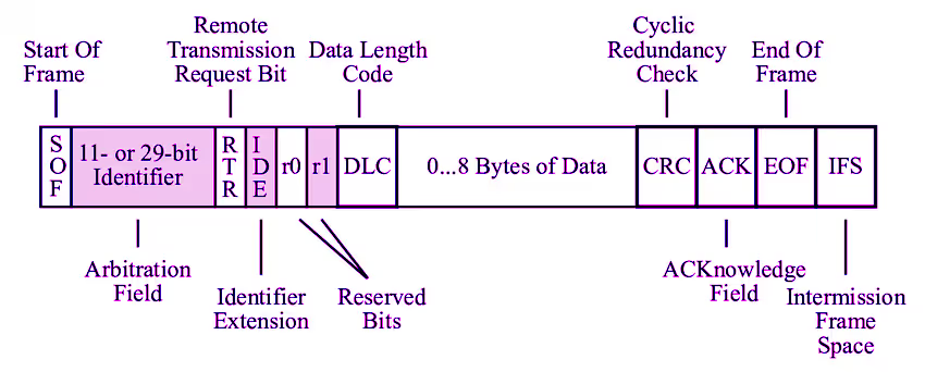
A CAN frame is made up of several fields, each serving a specific purpose in communication:
- Identifier (ID)
The Identifier represents the ID of the transmitting device or the type of message being sent. It also determines the priority of the message on the bus.
- 11-bit ID: Standard Identifier
- 29-bit ID: Extended Identifier
Lower ID values have higher priority during bus arbitration.
- RTR (Remote Transmission Request)
The RTR bit specifies the type of CAN frame:
0: Data Frame (contains data)1: Remote Frame (requests data from another node)
In most STM32 applications, you will primarily use data frames.
- IDE (Identifier Extension)
The IDE bit indicates the type of identifier used:
0: Standard ID (11-bit)1: Extended ID (29-bit)
This bit helps the CAN controller correctly interpret the frame format.
- Reserved Bit (r)
The reserved bit is included for protocol compatibility and future extensions. It does not carry useful information for the application and is handled automatically by the CAN controller.
- DLC (Data Length Code)
The DLC field specifies the number of data bytes contained in the frame.
- Valid range: 0 to 8 bytes (for Classical CAN)
This allows flexible payload sizes depending on application needs.
- Data Field
The Data Field carries the actual application data.
- Size: 0 to 8 bytes
- Contents are completely user-defined
This is the main field you will work with when sending and receiving CAN messages in STM32.
- CRC (Cyclic Redundancy Check)
The CRC field is used for error detection. It allows the receiving nodes to verify that the message was received correctly without corruption.
In STM32 applications, CRC handling is fully managed by the CAN hardware and HAL library, so you do not need to implement it manually.
- ACK (Acknowledgment)
The ACK field is used to confirm successful reception of the message. If at least one node receives the message correctly, it sends an acknowledgment.
This process is also automatically handled by the CAN controller and HAL driver.
What We Will Focus On in This Tutorial
In this tutorial, we will mainly work with:
- Identifier (ID)
- DLC
- Data Field
The remaining fields, such as CRC, ACK, arbitration, and error handling, are taken care of by the STM32 CAN hardware and HAL library, allowing us to focus on application-level communication rather than protocol internals.
Wiring the STM32 CAN Bus with MCP2551
To establish CAN bus communication between two STM32 boards, we use MCP2551 CAN transceivers. Each STM32 is connected to its own MCP2551, which handles the physical layer signaling required by the CAN protocol. The two transceivers are then interconnected using the CANH and CANL lines to form the CAN bus.
To maintain proper signal integrity and prevent reflections on the bus, a 120 Ω termination resistor must be placed between CANH and CANL. This resistor is typically required at each end of the CAN bus.
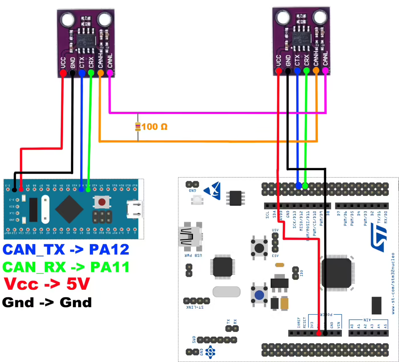
STM32 to MCP2551 Connections
For each STM32 board, connect the CAN peripheral pins to the MCP2551 as follows:
- CAN_TX (PA12) is connected to the TXD pin of the MCP2551
- CAN_RX (PA11) is connected to the RXD pin of the MCP2551
- 5V (VCC) is connected to the VDD pin of the MCP2551
- GND is connected to the VSS pin of the MCP2551
| STM32 Pin | MCP2551 Pin | Description |
|---|---|---|
| PA12 | TXD | CAN transmit data |
| PA11 | RXD | CAN receive data |
| 5V | VDD | Power supply |
| GND | VSS | Ground |
Note:
The MCP2551 requires 4.7–5.2V on VDD. Supplying 3.3V is the most common wiring mistake and will prevent communication in Normal Mode even if Loopback works fine.
MCP2551 to CAN Bus Connections
The MCP2551 transceivers are connected together through the CAN bus lines:
- CANH of one MCP2551 is connected to CANH of the other MCP2551
- CANL of one MCP2551 is connected to CANL of the other MCP2551
- A 120 Ω termination resistor is placed between CANH and CANL
| MCP2551 Pin | Bus Connection | Description |
|---|---|---|
| CANH | CANH | CAN high line |
| CANL | CANL | CAN low line |
| CANH ↔ CANL | 120 Ω Resistor | Bus termination |
CubeMX GPIO and Baud Rate Configuration
To set up CAN communication in STM32, we need to configure the CAN peripheral in CubeMX and generate the initialization code with HAL. This setup includes selecting the CAN mode, setting bit timings, and enabling the required GPIO pins for CANH and CANL.
The CubeMX Configuration for the CAN Peripheral is shown below.
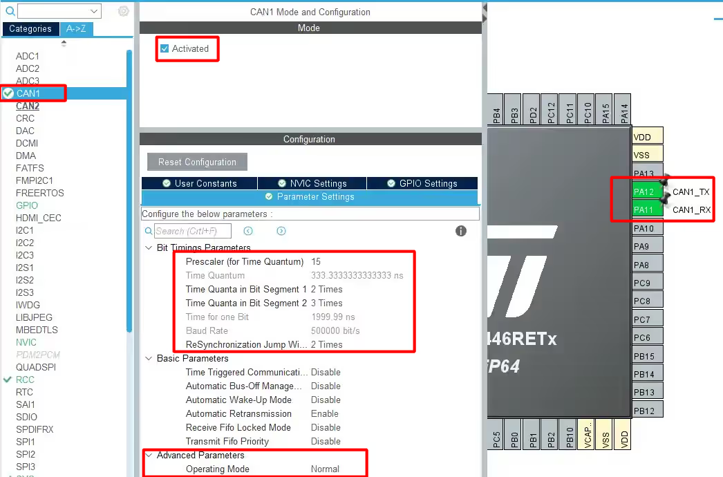
I am using CAN1 for this tutorial.
- Here the BAUD RATE is set to 500000 bps. You can try different different combinations for Prescaler and Time Quanta to achieve this.
- The Operating Mode is NORMAL Mode.
- Pins PA11 and PA12 are configured as CAN_RX and CAN_TX.
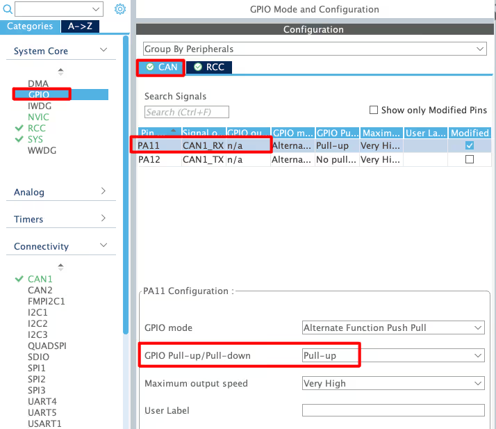
We also need to enable the pull-up resistor for the RX pin. This ensures the pin stays at a defined logic level when no signal is present, which helps avoid unwanted noise or false readings on the CAN bus.
STM32 CAN Example: CubeMX, Code & Results
After configuring the CAN peripheral and connecting the STM32 with the MCP2551 transceiver, the next step is to actually send data over the CAN bus.
Transmitting a CAN Data Frame
To Transmit the data, we first prepare the CAN frame by setting the header and filling in the data bytes. Then, we use the HAL functions to transmit the frame, which allows the STM32 to communicate with other nodes on the bus in real time.
Preparing the CAN Data Frame
Before we send any data, we need to prepare the CAN frame. This involves setting up the TxHeader with the message identifier, frame type, and data length, and then filling the TxData array with the actual bytes we want to transmit.
CAN_TxHeaderTypeDef   TxHeader;
uint8_t               TxData[8];
uint32_t TxMailbox;- Here
TxHeaderwill be used to store the header information, like RTR, DLC, etc. This is the typeCAN_TxHeaderTypeDef. TxDatais used to store the data that we are going to transmit over the CAN bus.TxMailboxis the mailbox, which will be sent to the CAN bus.
Next, we will place the required values into TxHeader and TxData. The header will hold details like the identifier and data length, while the data array will store the actual bytes we want to transmit over the CAN bus.
TxHeader.IDE = CAN_ID_STD;
TxHeader.StdId = 0x446;
TxHeader.RTR = CAN_RTR_DATA;
TxHeader.DLC = 2;

TxData[0] = 50;
TxData[1] = 0xAA;- Here
CAN_ID_STDmeans that we are using the Standard ID (not extended) 0x446is the Identifier. This is the ID of the Transmitter, and it should be maximum 11 bit wide for the Standard ID.CAN_RTR_DATAindicates that we are sending a data frameDLCis the Length of data bytes, and here we are sending 2 data Bytes- Finally, store the 2 data bytes to be transmitted in the
TxDataarray
Sending the CAN Data Frame
Once the frame is ready, we can send it over the CAN bus using the HAL function provided in STM32CubeMX. At this stage, the STM32 passes the header and data to the CAN peripheral, which then communicates with the MCP2551 transceiver.
if (HAL_CAN_AddTxMessage(&hcan1, &TxHeader, TxData, &TxMailbox) != HAL_OK)
{
   Error_Handler ();
}This can be done by using the function HAL_CAN_AddTxMessage. It have the following parameters
hcan1is the instance of the CAN, that we are using.TxHeaderis the Header of the message.TxDatais the Data field.TxMailboxis the mailbox, which will carry the header and data message.
Result of CAN Data Transmission in STM32
The image below shows the waveform captured during a CAN data frame transmission from the STM32. It highlights different fields of the frame, such as the identifier, control bits, data bytes, and CRC value.
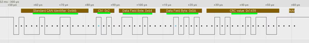
- Standard CAN Identifier (0x446): This is the message ID that defines the priority of the frame.
- Control Field (0x2): It specifies the type of frame and the data length (DLC, RTR, IDE).
- Data Field Bytes (0x64, 0x0A): The 2 bytes of data (Payload) we are transmitting.
- CRC Value (0x1459): This field ensures error detection by verifying data integrity.
- ACK/NACK: At the end of the frame, acknowledgment bits confirms successful reception or failure.
This result confirms that the STM32 successfully prepared and transmitted a valid CAN bus frame with the configured data.
When the CAN bus transmits a message, all connected devices can see it. However, each device’s filter configuration decides whether to accept it. The device receives and processes the message only if it matches the defined filter rules.
STM32 CAN Filter Configuration: ID Mask & Filter Banks
To reduce CPU load and avoid handling unwanted messages in software, STM32 microcontrollers include built-in filters inside the CAN peripheral. These filters decide which messages should be accepted and which should be ignored. Let’s take a closer look at how they work.
  CAN_FilterTypeDef canfilterconfig;

  canfilterconfig.FilterActivation = CAN_FILTER_ENABLE;
  canfilterconfig.FilterBank = 18;  // which filter bank to use from the assigned ones
  canfilterconfig.FilterFIFOAssignment = CAN_FILTER_FIFO0;
  canfilterconfig.FilterIdHigh = 0x446<<5;
  canfilterconfig.FilterIdLow = 0;
  canfilterconfig.FilterMaskIdHigh = 0x446<<5;
  canfilterconfig.FilterMaskIdLow = 0x0000;
  canfilterconfig.FilterMode = CAN_FILTERMODE_IDMASK;
  canfilterconfig.FilterScale = CAN_FILTERSCALE_32BIT;
  canfilterconfig.SlaveStartFilterBank = 20;  // how many filters to assign to the CAN1 (master can)

HAL_CAN_ConfigFilter(&hcan1, &canfilterconfig);- Enable Filters with FilterActivation
You must enable filters using theFilterActivationparameter. Without enabling them, no filtering takes place. - Assign and Select Filter Banks
- On controllers with dual CAN peripherals, you can distribute 28 Filter Banks between CAN1 and CAN2. For example, assign 20 Banks to CAN1 (SlaveStartFilterBank) and the rest to CAN2, then select a specific Bank (e.g., Bank 18) for filtering.
- On controllers with a single CAN peripheral, you can only use Banks 0–13.
- Configure Filter Parameters
- Use
FilterFIFOAssignmentto decide which FIFO (FIFO0 or FIFO1) will store received messages. - Set
FilterModeto either Mask Mode (compare selected bits) or List Mode (compare full IDs). Mask Mode is often more practical. - Choose
FilterScaleto use either one 32-bit register or two 16-bit registers. - Set
FilterIdHighto define which ID bits to compare (e.g., shift the STD ID by 5 because it starts at bit 5). - Set
FilterMaskIdHighto enable comparison of specific bits between the ID register and the incoming ID.
- Use
I recommend watching the video below. It demonstrates the working example in action, which explains the concept more clearly than text alone.
STM32 CAN Bus Loopback Mode & Filter Configuration
Watch how to set up CAN loopback mode and configure message filtering on an STM32 microcontroller.
Receiving CAN Messages via FIFO Interrupt
To handle incoming messages efficiently, we will use an interrupt for the RX FIFO. Whenever a message passes the filter, the CAN peripheral triggers an interrupt, allowing the STM32 to capture the data immediately. The first step in this process is enabling the CAN1 RX0 interrupt in CubeMX.
Enabling the CAN1 RX0 Interrupt in CubeMX
The image below shows the configuration of the CAN1 RX0 interrupt in STM32CubeMX.
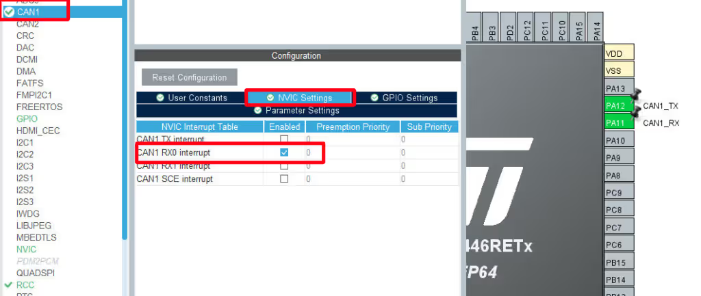
When you enable this interrupt, the STM32 automatically triggers the Interrupt Service Routine (ISR) each time a new CAN message passes through the filter and enters the RX FIFO 0 buffer. This allows the microcontroller to receive messages instantly without continuous polling, which reduces CPU load and improves overall efficiency.
Handling CAN Message Reception with Interrupts
To receive messages efficiently, we enable CAN notifications inside the main() function. This mechanism triggers an interrupt whenever a new message arrives in RX FIFO0 and automatically executes the corresponding callback function.
In the main function, we activate the notification using:
  if (HAL_CAN_ActivateNotification(&hcan1, CAN_IT_RX_FIFO0_MSG_PENDING) != HAL_OK)
  {
	  Error_Handler();
}Here, we enable the CAN_IT_RX_FIFO0_MSG_PENDING interrupt, which triggers whenever a new message is pending in RX FIFO0.
Once the interrupt occurs, the callback function HAL_CAN_RxFifo0MsgPendingCallback is called. In this function, we retrieve the received message header and data, and perform further checks if required.
CAN_RxHeaderTypeDef   RxHeader;
uint8_t               RxData[8];

void HAL_CAN_RxFifo0MsgPendingCallback(CAN_HandleTypeDef *hcan)
{
  if (HAL_CAN_GetRxMessage(hcan, CAN_RX_FIFO0, &RxHeader, RxData) != HAL_OK)
  {
    Error_Handler();
  }
  if ((RxHeader.StdId == 0x103))
  {
	  datacheck = 1;
  }
}- Here we will Receive the message from RX_FIFO 0.
- The program stores the message header in
RxHeaderand the data inRxData. - It then checks whether the message was received from ID
0x103; if true, it sets thedatacheckflag.
Note:
Board A transmits at ID 0x446; Board B transmits at ID 0x103. Each board’s filter is set to accept the other’s ID. Here F446 is configured to receive data from F103, hence the ID for the same is being use.
In the main loop, we can use the datacheck flag to perform actions. For example, if the flag is set, we turn on an LED:
if (datacheck)
{
 HAL_GPIO_WritePin(GPIOA, GPIO_PIN_5, GPIO_PIN_SET);
}This way, only when a valid CAN message with ID 0x103 is received, the LED will light up.
STM32 CAN Bus Communication in Normal Mode — Video Tutorial
Watch the complete walkthrough of this tutorial — wiring two STM32 boards with MCP2551 transceivers, configuring CAN1 in Normal Mode in CubeMX, writing HAL code to build and transmit a CAN data frame, setting up filter banks with ID mask mode, enabling the RX FIFO0 interrupt, and verifying live CAN communication between the two boards.
STM32 CAN Bus: Frequently Asked Questions
Conclusion
In this tutorial, we explored how to use the CAN protocol with STM32, starting from the essential hardware connections and moving through peripheral configuration, message transmission, and reception. We also examined how CAN filters, RX FIFOs, and interrupts work together to ensure that only relevant messages are processed, keeping the communication efficient and reliable. By handling reception through interrupts and callbacks, we significantly reduce CPU load and follow best practices for real-time embedded systems.
With this foundation, you are now well equipped to build more advanced CAN-based applications, such as multi-node networks, distributed sensor systems, motor controllers, or automotive-style communication setups. The same concepts demonstrated here scale naturally as the network grows in size and complexity.
If you want to take the next step, check out my guide on FDCAN Normal Mode in STM32, where we dive into Flexible Data-Rate CAN (FDCAN). This allows higher data throughput, larger payloads, and more robust communication, which is ideal for modern, high-performance embedded applications.
Download STM32 CAN Bus Normal Mode Project Files
Complete CubeMX project and HAL source code for CAN bus communication between two STM32 boards using MCP2551 transceivers — including TX, RX, and filter configuration. Free to download — support the work if it helped you.
Browse More STM32 CAN Tutorials


I am working on the same project you explained here, but my boards are nucleo and discovery. I am a completely beginner in it can you please help me in my project
Why are there two reserved bits (r0, r1) after the ID and before the data length code, if according to the documentation of Bosch there is one reserved bit r0?
Hello,
Thanks for your useful tutorials.
I am going to use Extended CAN of stm32 but I could not find how I can do it. Is it possible you help and tell me which part of the code need to be changed.
Regards,
Mehrdad
What exactly is Extended CAN ?
Olá amigo, qualo modelo das placas, a menor é a BluePill e a outra é que núcleo?
Hi, I am using stm32f407 I tried your code but there is no data is received,i don’t know what I
Missed
Hey man! Big thanks, your code examples are a great help, especially this one. Video tutorials on youtube are great too. (if only not for the robotic voice-over, but I understand how hard it is to make a proper voice-over)
super ra kaasi
Thank you very much for this helpful tutorial.
I also watched the vid on youtube for the can one master multiple slaves.
Do I understand right: I can only tell a controller to which other controllers (IDs) to listen to, but I cannot tell the master to send a message to a certain slave?
So all slaves listen to the master, and the master message passes the filter of all slaves, and I have to pack a “address information” into the data part of the message, which every slave has to check then?
I would be very happy if you could clarify this for me 🙂
Almost..
Except that the master does not manage to pass through the filters of all slaves. The filters decides which master to accept the data from.
forgot to say thanks for the fast reply.
so: thank you!
Thank you very much Sir.
I have to establish CAN bus communication between two stm32f407VET6 boards and it doesn’t work for me, can I directly connect tx to tx and rx to rx? because I understand that the boards have two integrated can, I do not have the MCP2551, I have two MCP2515
You need can transceivers, you can’t directly connect them.
MCP2515 is SPI to CAN, and this tutorial does not cover that.
Hi, I am using STM32F103C8 and I have tried your code and setup. However, your code is working on “loopback mode” and not working in “Normal Mode”. I don’t know why, it won’t transmit and wont receive message. I believe there is other people commented this problem on your youtube (CAN Normal Mode) video but has yet get an answer, also there are many other facing this issue as well (stack forum or st community) both also do not have answer. If anyone reading this and have solution please share it here. Thank you.
Extra Info:
If I configure in loopback mode, I can transmit message from MCU to other CAN analyzer device and to internal Rx (I verified by oscilloscope and CAN analyzer device successfully received.)
Do you using STM32F103C8 2 board right ? I have problem same with you.
I am not using STM32F103C8 blue pill board. Mine is just the microcontroller(STM32F103C8T6) itself. I owned a STM32F303 Nucleo board as well and Have tried controllertech’s code and it is working.
Also list of configurations I have tried on STM32F103:
1) adjusting the sample point to ~80%
2) tried internal clk and external clk
3) FIFO0 & FIFO1
4) different baudrate
5) CAN port remapping
6) CAN Config Filter ID etc
7) check on hardware wiring, connection etc
8) new or spare STM32F103
9) ST’s example code in STM32Cube_FW_F1_V1.X.X
Unfortunately, non of them is working. At this point I think STM32F103C8 CAN peripheral is broken. I wish I have a blue pill, I believe STM32F103 on blue pill will not have this issue.
Also If anyone has solution please share it here Thank you.
Finally I get it to work. The problem is Vcc. I am supplying 3.3V to transceiver which is not enough. The transceiver I am using required Vcc in range of 4.7 – 5.2 V. Lesson learned, read datasheet thoroughly.
Thanks for sharing!
Your comment helped me to realize where the past 6 hours have gone.
I am using MCP2562 and it has 2 power supplies, Vio and Vdd. I thought both are 3.3V, but it turns out that Vdd should be 5V.
Lesson learned – read carefully the documentation before soldering 😉
can i see your program and setting on stm cube??
Hello,
ı want to know, which is id transmitted message to me? How can ı lean?
“HAL_CAN_AddTxMessage” methods accept uint8_t data, can ı transmit array?
In my scenario I have a master and 5 slaves. 5 slaves are sending messages to master. And I want to know, which slave sent the message to the master?
Thank you for this post.
in the received callback, you can check it by using ID = RxHeader.StdID;
the ID will be stored in the ID variable
Нужны stm32 can
Do you have any good sources on what modifications need to be made to use the FDCAN peripheral on the H7 processors? I can see some signals making it back and forth between the two boards but they analyze as Errors and after two exchanges back and forth the CAN State get stuck in BUSY.
All fixed. The CAN was BUSY because I was forgetting to call GetMessage and the buffer I’m guessing was full. Using this tutorial mixed with the example project from HAL on FDCAN worked great. Thanks!
Hello Thanks for the tutorial it was helpful but i have one problem, i can only receive the data in Blue Pill but the data sent by the Bull pill is not received at F4 controller and i am using CAN BUS 2 for the communication i need as all suggested by you. but still no way i could achieve it.
could you please guide me what wrong i am doing.
Thanks
With regards
Lakshminarayana KS
I solved the issue it was wit my filter Bank Selection.
Is their anyway to hold the bus and send more than 8 bytes of Data ???
thanks
nope. CAN will only support 8 bytes at once.
super bro
Hey, This worked well.
Now is it possible to use multiple addresses with a device to transmit data?
That is the slave has multiple addresses for a single device, each address has different data values. Now the master accesses the slave with multiple addresses according to the required data values.
For example:- The master requires the data”time” in the slave, the master uses the particular address(0x102) for the data “time”.If the master requires the data “Brightness” in the slave, the master uses the particular address(0x103) for the data “Brightness”.Likewise….
Can you give me a solution to work out this in STM32F103C8T6?
I use CAN1 for F407VG, it works normal but use CAN2 it does not receive data. I dont know why?
check out the filter configuration properly. There are different filters provided for both the CANs. I have mentioned that in the first video
I don’t use the filter configuration for CAN2, it sends data normally but still does not receive data.
Hello, i don’t know what the value 0x443 in STD ID is for, while on the receiver side we check the value 0x103.
I have made the necessary corrections. Actually I was trying to show multiple IDs, you should watch the video to understand it
Hi Admin,
Thank you so much for your tutorials…!
I am STM32F103 CAN (MCP2561 as CAN transceiver) with 500kbps and CAN BUS ANALYZER to check the CAN msgs.
Here am sending 3 CAN msgs for every 100ms but some times some msgs are missing so that am getting the CAN cycle time as 200ms and I have followed the same procedure as above but some times my CAN msgs are missing.
what I have to do eliminate this error ?
Thanks again