How to Use 4×4 keypad with STM32
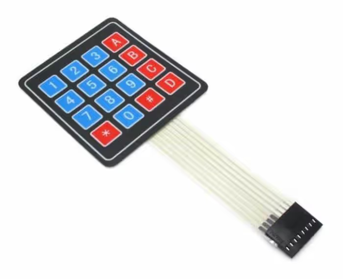
Today in this tutorial we will interface a 4×4 keypad with STM32. I am going to use STM32F103C8 microcontroller and the keypad is a membrane switch 4×4 matrix keypad, which is shown in the image below
It does not matter which keypad you use or how many KEYs it have. We will use a method which can be used universally with any type of keypad or microcontroller out there.
VIDEO TUTORIAL
You can check the video to see the complete explanation and working of this project.
Check out the Video Below
HOW TO
Let’s start this discussion on How to actually interface a keypad with any microcontroller. The concept is pretty simple. The Keys in the keypad are divided into ROWs and COLUMNs and we are going to use these to find out which key has been pressed.
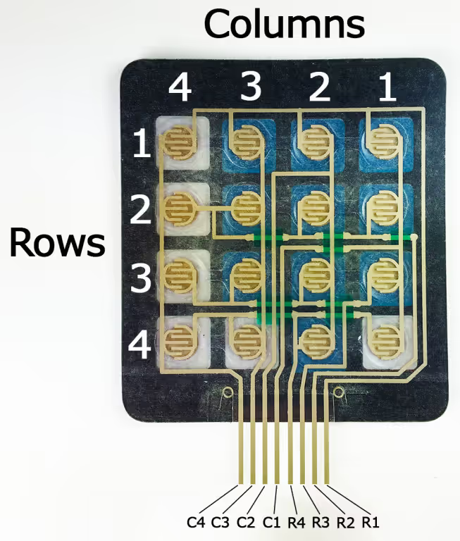
Below is the image showing how the keys are connected in the form of Rows and Columns.
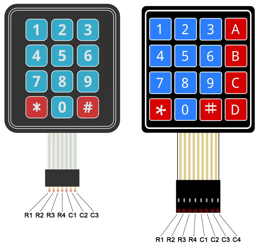
As shown in the picture above, the Keypad have 16 keys and they are divided in 4 ROWs and 4 COLUMNs. All the keys in a single ROW are interconnected and all keys in a single COL are interconnected.
We will connect the ROWs to output pins and the COLs to the input pins.
To identify the key pressed, we will pull one of the ROWs to LOW and other ROWs to HIGH. Whenever a key is pressed, the connection between ROW and COL gets completed and the COL pin will read 0. Now both, the ROW and COL will be 0 and we will know which pin has been pressed.
For eg- Let’s say I pressed the key 5. To identify this, we need to pull the R2 to LOW and than check for the Columns. Whenever the ‘5’ is pressed, the C2 will be pulled LOW as the connection between R2 and C2 will be completed. And for this combination of R2 and C2 being LOW, will be assigned value ‘5’.
The method I am using here is the POLLING, as the microcontroller keep on polling for the key pressed. An interrupt on the key press would obviously be better which I will try to implement in coming days.
Connection & Configuration
Pin Configuration
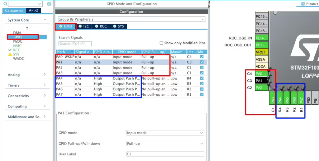
Below is the image showing the pin configuration in the cubeMX.
As you can see in the image above, I have configured 4 pins PA0 – PA3 as input pins and renamed them C1 – C4. These are the pins where we will connect the column pins. These pins are pulled Up by default.
The pins PA4 – PA7 are configured as the output pins and they are renamed as R1 – R4. These are the pins where we will connect the Row pins. These pins are pulled LOW by default.
I2C Configuration
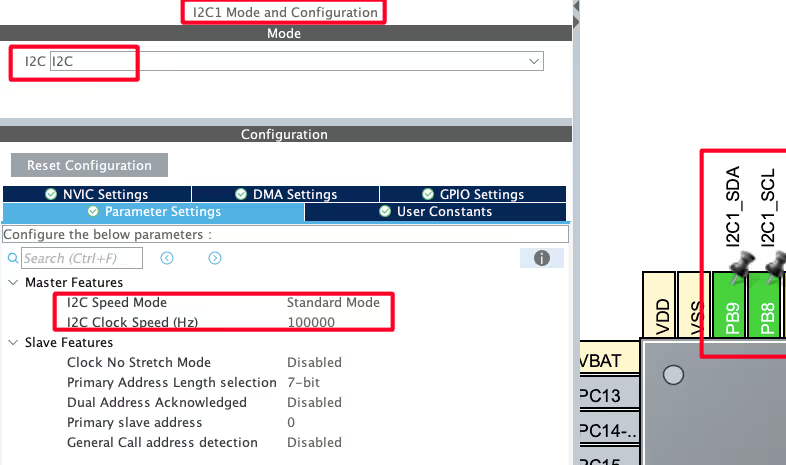
We are using the LCD1602 to display the current Time and Date. The LCD is connected using the PCF8574 I2C extender. Below is the image showing the I2C configuration.
I am using the I2C1 to connect the LCD. The I2C is configured in the standard mode with the clock speed set to 100KHz. The pins PB8 and PB9 are configured as the SCL and SDA pins.
We have already covered how to interface the LCD via I2C with STM32. You can check out the tutorial for more details.
Connection
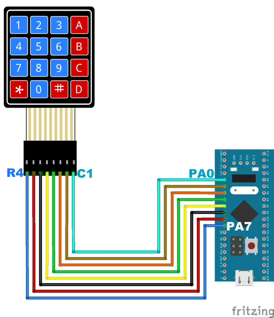
Below is the image showing the connection between the keypad and the STM32.
As you can see in the image above, the pins PA7 – PA4 are connected to the Row pins R4 – R1 respectively. And the pins PA3 – PA0 are connected to the Column pins C4 – C1 respectively.
Some Insight into the CODE
We will define a separate function to read the data in the blocking mode.
char read_keypad (void)
{
	/* Pull ROW 1 to LOW and all other ROWs to HIGH */
	HAL_GPIO_WritePin (R1_GPIO_Port, R1_Pin, GPIO_PIN_RESET);  //Pull the R1 low
	HAL_GPIO_WritePin (R2_GPIO_Port, R2_Pin, GPIO_PIN_SET);  // Pull the R2 High
	HAL_GPIO_WritePin (R3_GPIO_Port, R3_Pin, GPIO_PIN_SET);  // Pull the R3 High
	HAL_GPIO_WritePin (R4_GPIO_Port, R4_Pin, GPIO_PIN_SET);  // Pull the R4 High

	if (!(HAL_GPIO_ReadPin (C1_GPIO_Port, C1_Pin)))   // if the Col 1 is low
	{
		while (!(HAL_GPIO_ReadPin (C1_GPIO_Port, C1_Pin)));   // wait till the button is pressed
		return '1';
	}

	if (!(HAL_GPIO_ReadPin (C2_GPIO_Port, C2_Pin)))   // if the Col 2 is low
	{
		while (!(HAL_GPIO_ReadPin (C2_GPIO_Port, C2_Pin)));   // wait till the button is pressed
		return '2';
	}

	if (!(HAL_GPIO_ReadPin (C3_GPIO_Port, C3_Pin)))   // if the Col 3 is low
	{
		while (!(HAL_GPIO_ReadPin (C3_GPIO_Port, C3_Pin)));   // wait till the button is pressed
		return '3';
	}

	if (!(HAL_GPIO_ReadPin (C4_GPIO_Port, C4_Pin)))   // if the Col 4 is low
	{
		while (!(HAL_GPIO_ReadPin (C4_GPIO_Port, C4_Pin)));   // wait till the button is pressed
		return 'A';
	}

    ..........
    ..........
}The function read_keypad will read the keypad in the blocking mode and return the character(Key) detected.
Here first we will pull the ROW1 to LOW and all other ROWs to HIGH. Than we keep monitoring for the columns. If COL1 is low, that means the key pressed is ‘1’ or else if the COL2 is low, that means the key pressed is ‘2’ and so on..
similarly, we do the same for other ROWs as well, until all ROWs are covered.
The main function
int main()
{
  ....
  lcd_init();
  lcd_clear();
  lcd_put_cur(0, 0);
  lcd_send_string("KEY: ");
  while (1)
  {
	  char key = read_keypad();
	  if (key!=0x01)
	  {
		  lcd_send_data(key);
	  }
  }
} Inside the main function, we will initialise the LCD and send a fixed string (KEY: ) to it.
Then inside the while loop, read the key pressed on the keypad. If the key is pressed, we will print the key character on the display.
Result
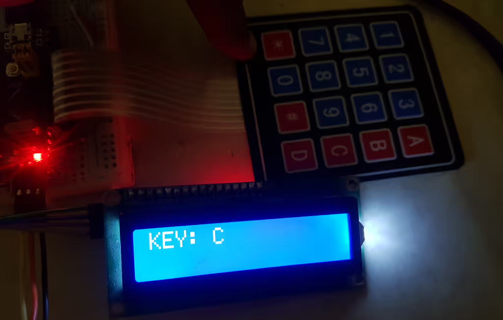
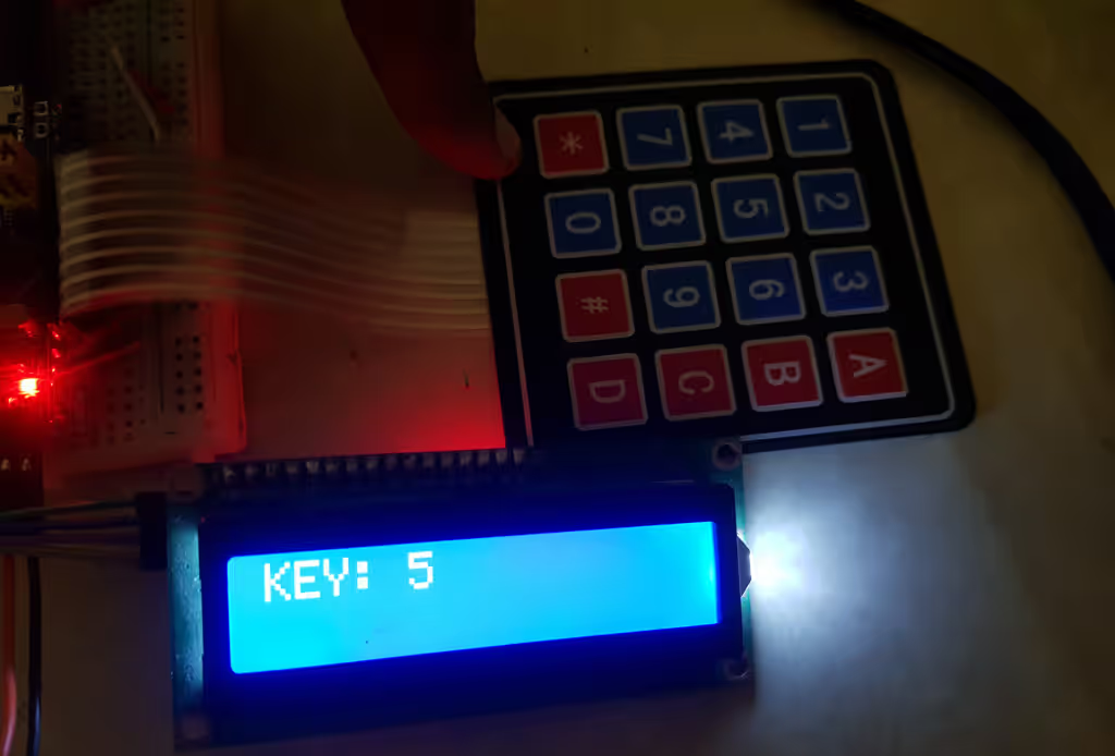
Below are the images showing the output on the LCD.
You can see the Key characters are displaying on the LCD.
Info
You can help with the development by DONATING Below.
To download the project, click the DOWNLOAD button.

I appreciate you for this tutorial. would you please provide another tutorial for interrupt method as you said above.
thanks in advance
hi would you like to please share the wiring diagram
how to connect both keypad and LCD with STM
no debouncing ??
hi
4*4 keypad download link do not work
It’s working fine.. maybe some issues earlier