Updated On: April 1, 2026
STM32 Custom Bootloader: Implementing OTA FLAG Mechanism
In an STM32 system, the bootloader usually controls the update process. However, the application must tell the bootloader when an update is required.
In this tutorial, we will implement a simple OTA request mechanism using a flash-based flag. The application will set this flag and reset the MCU. The bootloader will detect the flag, clear it, and start the OTA process.
Since we are not downloading firmware from a server yet, we will simulate the OTA request using a button. This makes the concept easy to understand and test.
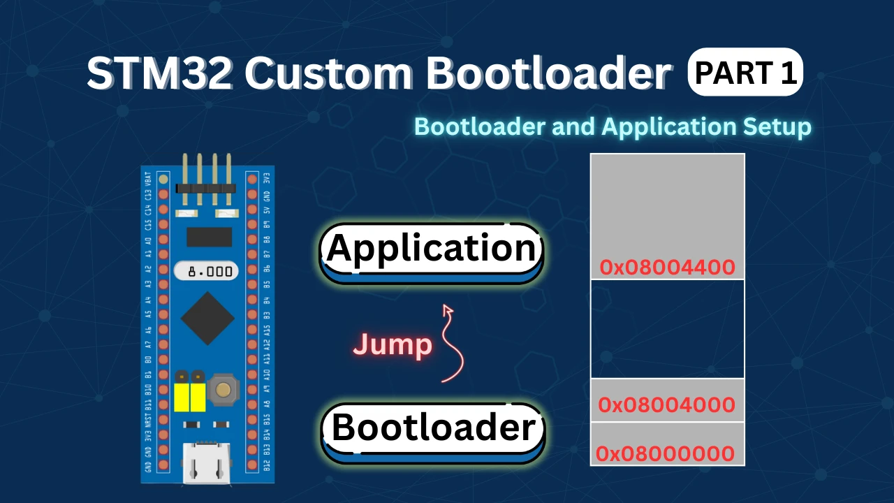
This tutorial is a continuation of the STM32 custom bootloader series. If you have not seen the previous part on CRC and size validation, you should read it first.
Understanding OTA Update Flow in STM32 Bootloader
Before implementing OTA in code, it is important to understand how the OTA update flow works in an STM32 bootloader-based system.
In this design, the bootloader controls the startup process, while the application decides when an update is required. To communicate this request safely, we use a flash-based OTA flag stored inside the application header.
The image below shows the complete OTA update flow between the application and the bootloader.
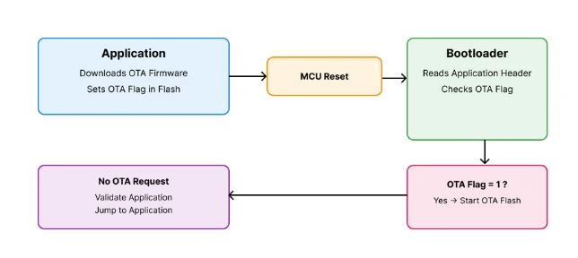
The application sets the OTA flag and resets the MCU. The bootloader checks the flag and decides whether to start OTA or jump to the application.
This approach keeps the system reliable, simple, and easy to debug. Let us now understand each part of this flow in detail.
What Is an OTA Request Flag
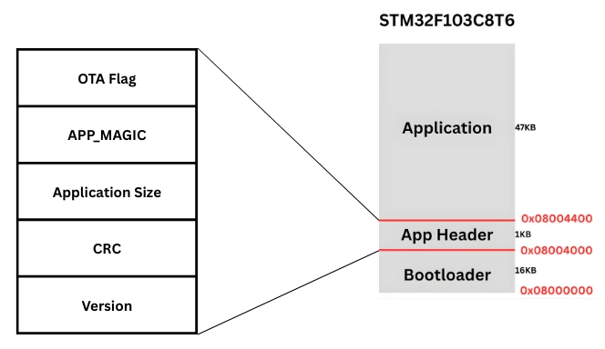
An OTA request flag is a small piece of data stored in flash memory. It is usually placed inside the application header, along with other information such as CRC and size.
This flag acts as a signal between the application and the bootloader.
- A value of
0means no OTA request - A value of
1means OTA update requested
Since flash memory is non-volatile, the flag remains valid even after a reset or power cycle. This makes it a reliable way to pass information to the bootloader.
In this tutorial, the OTA flag is stored as the first word of the application header.
Why the Application Should Trigger OTA
In a real product, the application is responsible for handling communication. It talks to the server, checks for updates, and downloads new firmware.
The bootloader, on the other hand, should stay simple and stable. It should only handle tasks like validation, flashing, and jumping to the application.
For this reason, the application should decide:
- When an update is available
- When the system is ready for flashing
Once the update is ready, the application:
- Sets the OTA flag in flash
- Resets the MCU
After reset, the bootloader takes over and performs the update. This separation of roles makes the system clean and maintainable.
How the Bootloader Detects OTA Request
When the MCU resets, the bootloader runs first. Before jumping to the application, it checks whether an OTA request is present.
The bootloader:
- Reads the application header from flash
- Checks the first word for the OTA flag value
If the value is 1, it means the application has requested an OTA update. The bootloader then:
- Clears the OTA flag
- Starts the OTA flashing process
If the flag is not set, the bootloader continues with its normal flow. It validates the application and jumps to it.
Application Side OTA Request Implementation
The application plays a key role in the OTA update process. It is responsible for deciding when an update is required and informing the bootloader about it.
In this section, we will focus on how the application raises an OTA request using a flash-based flag and a button input.
Since the actual OTA download is not implemented yet, we will simulate this behaviour using an external button. This helps us clearly understand the flow without adding extra complexity.
OTA Flag Location in Flash Memory
The OTA request flag is stored in the application header, which already contains important information such as the magic number, CRC, and application size.
Placing the OTA flag inside the application header has several advantages:
- The bootloader already knows where to read this data
- The flag survives reset and power cycles
- No extra flash region is required
In this implementation, the OTA flag is stored as the first word of the application header.
0-> No OTA request1-> OTA request active
Only this single word is modified during the OTA request. The rest of the application header remains unchanged.
Using External Button to Trigger OTA
In a real system, the OTA request would be triggered after:
- Downloading firmware from a server
- Verifying the downloaded image
Since this part is not implemented yet, we use a push button to simulate the OTA request.
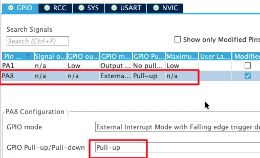
The button is connected to:
- PA8 configured as an external interrupt (EXTI)
- Internal pull-up resistor enabled
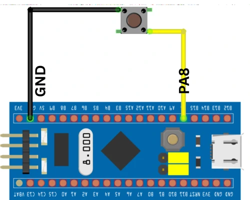
When the button is pressed:
- The pin goes low
- An external interrupt is generated
- The application starts the OTA request process
This approach makes testing easy and allows us to manually control the OTA flow.
GPIO EXTI Callback for OTA Request
When the button is pressed, the GPIO EXTI callback function is executed. The code below shows the EXTI callback used in the application.
void HAL_GPIO_EXTI_Callback(uint16_t GPIO_Pin)
{
    uint32_t wait = 10000;
    while (wait--);

    enable_ota_request();
}This callback does not directly modify flash memory. Instead, it calls a dedicated function that safely handles flash operations.
Writing OTA Flag From Application
Once the OTA request is triggered, the application must safely update the OTA flag in flash memory. This step is critical because flash memory cannot be modified like normal RAM. Any incorrect operation can corrupt the application header.
To avoid this, the application follows a read–modify–write approach. Only the OTA flag is updated, while the remaining header data stays unchanged.
Reading Application Header From Flash
Flash memory cannot be partially updated. So before making any change, the application first reads the entire application header into a buffer.
This is done using a flash read function that copies data word by word from flash to RAM.
flash_read_page(APP_HEADER_ADDR, flash_buffer);At this stage:
flash_buffercontains the full application header- No flash memory is modified yet
This step ensures we do not lose important information such as CRC and application size.
Setting OTA Flag Safely
After reading the header, the application modifies only the first word, which represents the OTA flag.
flash_buffer[0] = OTA_FLAG_START;Here:
OTA_FLAG_STARTis defined as1- Writing
1indicates that an OTA update is requested
Once the buffer is updated, the application erases the flash page containing the header and then writes the modified buffer back to flash.
This approach is safe and works reliably across resets.
Resetting MCU After OTA Request
After updating the OTA flag, the application must restart the MCU. This allows the bootloader to run again and check the OTA request.
NVIC_SystemReset();Once the reset happens:
- The bootloader starts executing
- It reads the application header
- It detects the OTA flag and starts the update process
Complete Application OTA Request Code
The code below shows the complete implementation used by the application to raise an OTA request.
#define OTA_FLAG_START     1

uint32_t flash_buffer[5];

void enable_ota_request(void)
{
    HAL_FLASH_Unlock();

    flash_read_page(APP_HEADER_ADDR, flash_buffer);

    /* Update only first word */
    flash_buffer[0] = OTA_FLAG_START;

    flash_erase_page(APP_HEADER_ADDR);

    flash_write_page(APP_HEADER_ADDR, flash_buffer);

    HAL_FLASH_Lock();

    NVIC_SystemReset();
}This function is simple, safe, and effective. It cleanly hands over control to the bootloader without affecting the rest of the application.
Generating Application CRC and Size Using Python Script
Once the CRC-ready application binary is generated, the next step is to calculate the application CRC and application size. These values are generated on the PC side and then stored inside the application header.
The bootloader later reads these values and uses them to validate the application before execution.
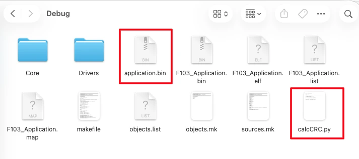
calcCRC.py Script Overview
To calculate the CRC and size, we use a simple Python script called calcCRC.py.
This script:
- Reads the application binary file
- Calculates CRC32 using a standard algorithm
- Prints the CRC value and application size
Since the CRC must be calculated on the binary without the header, this script is run on the clean application binary generated in the previous step.
Generating CRC32 and Application Size
First, copy the calcCRC.py script into the Debug folder of the application project. This is the same folder where the new application binary file is generated. Placing the script here makes it easy to access the binary file.
Now open a terminal inside the Debug folder and run the script. Make sure Python is installed on your system before running it.
When the script runs, it reads the application binary and prints:
- The CRC32 value
- The application size in bytes
The image below shows the terminal output displaying the calculated CRC and application size.

These values will be used in the next step.
Updating the Application Header Values
Once the CRC and size are generated, copy these values and update them in the application header structure. The application header is defined inside the application code and stored in a dedicated flash section.
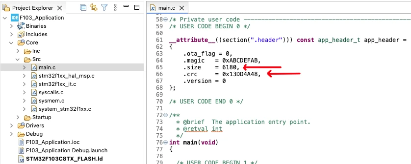
Only the header values are updated at this stage. The application binary used for CRC calculation remains unchanged.
After updating the header values, rebuild the application project. Since the header section is excluded from CRC calculation, the CRC value does not change after rebuilding. These updated header values allow the bootloader to correctly validate the application during startup.
Bootloader Side OTA Detection Logic
The bootloader is the first code that runs after a reset. Before jumping to the application, it must check whether an OTA update is requested.
To keep the bootloader simple and reliable, it only performs three tasks:
- Read the OTA flag from flash
- Decide whether OTA is required
- Clear the flag after detection
Checking OTA Flag in Application Header
As soon as the bootloader starts, it reads the application header from flash memory.
The OTA flag is stored in the first word of the header. The bootloader checks this value to determine the next action.
int check_ota_request (void)
{
    flash_read_page(APP_HEADER_ADDR, flash_buffer);

    if (flash_buffer[0] == OTA_FLAG_START)
        return 0;

    return 1;
}Here:
- A return value of
0means OTA request detected - A return value of
1means no OTA request
This function is called before the application validation logic.
Clearing OTA Flag After Detection
Once the bootloader detects an OTA request, it must clear the flag immediately. This prevents the system from entering the OTA process again after the next reset.
The process is similar to how the application sets the flag:
- Read the application header into a buffer
- Modify only the OTA flag
- Erase the flash page
- Write the updated data back
void clear_ota_flag(void)
{
    HAL_FLASH_Unlock();

    flash_read_page(APP_HEADER_ADDR, flash_buffer);

    /* Update only first word */
    flash_buffer[0] = OTA_FLAG_CLEAR;

    flash_erase_page(APP_HEADER_ADDR);

    flash_write_page(APP_HEADER_ADDR, flash_buffer);

    HAL_FLASH_Lock();
}This ensures the OTA request is handled only once.
Simulating OTA Flash Process
Since the actual OTA flashing is not implemented yet, we simulate the process inside the bootloader.
If the OTA flag is detected:
- A message is printed on the serial console
- The OTA flag is cleared
- A red LED is toggled every 500 milliseconds
HAL_UART_Transmit(&huart1,
    (uint8_t *)"Inside Bootloader!!\r\n", 21, 100);

if (check_ota_request() == 0)
{
    HAL_UART_Transmit(&huart1,
        (uint8_t *)"OTA Requested... Flashing..\r\n", 29, 100);

    clear_ota_flag();

    while (1)
    {
        HAL_GPIO_TogglePin(GPIOA, GPIO_PIN_4);
        HAL_Delay(500);
    }
}This LED blinking represents the OTA flashing process. In later parts of the series, this section will be replaced with real firmware flashing logic.
Complete OTA Request Flow Explanation
Now that we have seen the application side and the bootloader side logic, it is important to understand the complete OTA request flow as a single sequence.
Application to Bootloader Control Flow
The OTA process always starts from the application.
The sequence is simple and predictable:
- The application decides that an OTA update is required
- It writes the OTA flag into the application header
- The MCU is reset using a system reset
- The bootloader starts executing after reset
- The bootloader checks the OTA flag
If the flag is set, the bootloader does not jump to the application. Instead, it enters the OTA update routine.
This clear separation ensures that:
- The application controls when OTA happens
- The bootloader controls how OTA is performed
Reset Behavior and Flag Handling
The reset plays a very important role in this design.
When the application resets the MCU:
- RAM contents are cleared
- Flash contents remain unchanged
- The OTA flag stays valid
After reset, the bootloader:
- Reads the application header
- Detects the OTA flag
- Clears the OTA flag
- Starts the OTA process
Once the OTA process is complete, the system can be reset again.
Because the bootloader already cleared the flag:
- The OTA check now fails
- The bootloader validates the application
- Control jumps back to the application
This mechanism prevents repeated OTA execution. It also gives you full control over the update process using a single flash-based flag.
Expected Output and Verification
Once the OTA request mechanism is implemented, we need to verify how the system behaves at runtime.
OTA Flashing State (OTA Flag Set)
This state occurs when the application sets the OTA flag and resets the MCU. After reset, the bootloader starts executing and detects that the OTA request flag is set.
At this point, you should observe the following behavior.
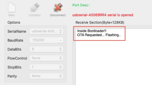
Serial Output
The image below shows the bootloader log indicating that an OTA request was detected and the flashing process has started.
LED Behavior
At the same time, the red LED starts blinking every 500 milliseconds. The gif below shows the red LED blinking continuously, indicating that the OTA flashing process is active.

This blinking LED represents the OTA update process. In later parts of the series, this section will contain the actual firmware flashing logic.
Normal Boot State (Jump to Application)
This state occurs after the bootloader clears the OTA flag and the board is reset again. Since the OTA flag is no longer set, the bootloader follows its normal execution path.
Serial Output
The image below shows the bootloader starting normally and jumping to the application without entering the OTA process.
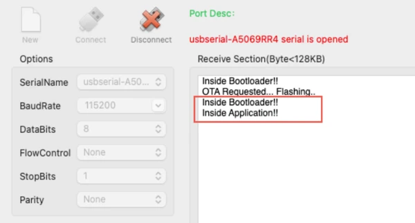
No OTA-related message is printed in this case.
LED Behavior
The gif below shows the Green LED blinking every 500 millisecond, indicating the Application code is running.

With this verification, we now have full control over how the application triggers OTA and how the bootloader responds.
Video Tutorial
STM32 OTA Bootloader Flag Mechanism (Video Tutorial)
Prefer video learning? Watch this tutorial where we implement an OTA request mechanism in a custom STM32 bootloader. This video explains how the application sets an OTA flag in flash memory and how the bootloader detects and clears this flag before starting the update process. You will also see how an external button is used to simulate an OTA request and how the bootloader responds during flashing.
Watch the STM32 OTA Bootloader VideoConclusion
In this tutorial, we learned how to implement a simple and reliable OTA request mechanism in an STM32 bootloader. We saw how the application can safely request an OTA update by setting a flash-based OTA flag, and how the bootloader detects and clears this flag before starting the update process. This approach keeps the bootloader clean while giving the application full control over when an update should happen.
This method is very useful in real-world embedded systems. The application handles communication and update decisions, while the bootloader focuses only on validation and flashing. Using a flash flag makes the system robust, as the information survives resets and power loss. It also prevents repeated OTA execution by clearing the flag at the right time, which avoids boot loops and unwanted behavior.
In the next part of this series, we will take this a step further and actually flash a new application image using the bootloader. Although the firmware will not be downloaded from a server yet, we will manually integrate it into the bootloader project to demonstrate the complete update flow. This will bring us closer to a fully working STM32 OTA update system.
More STM32 Bootloader Tutorials
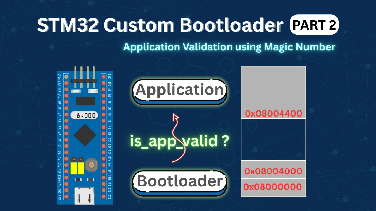
STM32 Custom Bootloader (Part 2): Application Validation Using Magic Number
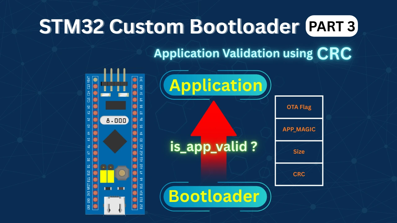
STM32 Custom Bootloader (Part 3): CRC Based Application Validation
STM32 Custom Bootloader (Part 5): Implementing OTA Update
STM32 OTA Bootloader PART 6: Flash OTA Update from TCP Server Using Ethernet
STM32 OTA Bootloader (PART 7): Wireless Firmware Update Using ESP8266 WiFi Module
STM32 Bootloader Project Download

STM32 Bootloader OTA Flag FAQs

Subscribe
Login
0 Comments
Newest
