
Updated On: February 6, 2026
Use UART Interrupt to Receive Data and Control LEDs
In Part 1 of this series, we learned how to send and receive data using UART polling on the TM4C123G Tiva C. Polling works for simple tasks, but it blocks the CPU and slows down your program.
UART interrupts solve this problem. With interrupts, the microcontroller can respond immediately when data arrives, without constantly checking the UART status. This makes your code faster, efficient, and suitable for real-world applications.
In this tutorial, we will show how to receive UART data using interrupts and use it to control LEDs. You will learn how to parse commands and toggle GPIO pins based on the received data.
Recommended Resources:
I have already covered how to create a project in CCStduio and configure system clock in the previous tutorials. This tutorial is going to be a continuation in this series, so you must read the following tutorials first:
- How to Setup CCStudio and build your first project with TM4C123G
- How to configure system clock in TM4C123G
Why UART Interrupts Are Useful on TM4C123G
Limitations of Polling Mode
In polling mode, the microcontroller continuously checks the UART to see if data has arrived. This works for small tasks, but it has several drawbacks:
- The CPU is busy waiting, which wastes processing time.
- The microcontroller cannot perform other tasks efficiently while waiting for data.
- For fast or unpredictable data, polling can miss characters if the CPU is doing something else.
Polling is simple but not suitable for responsive, real-time applications.
Advantages of Using UART Interrupts
With UART interrupts, the microcontroller does not have to constantly check the UART status. Instead, it is notified automatically when new data arrives.
Benefits include:
- Non-blocking operation: The CPU can execute other tasks while waiting for data.
- Immediate response: Incoming data triggers an interrupt service routine (ISR) instantly.
- Efficient and faster: No time wasted in busy waiting.
- Reliable for continuous or high-speed data: Reduces the chance of missing characters.
Using interrupts makes your code more responsive and CPU-friendly, which is ideal for projects like command-based LED control, sensors, or communication with other devices.
Polling vs Interrupts – A Quick Comparison
| Feature | Polling Mode | Interrupt Mode |
|---|---|---|
| CPU Usage | High (busy waiting) | Low (CPU free until data arrives) |
| Response Time | Depends on polling loop | Immediate (ISR triggers) |
| Complexity | Simple to implement | Slightly more complex (requires ISR) |
| Reliability | May miss data at high speed | Very reliable for incoming data |
| Best Use | Small, simple projects | Real-time or multitasking applications |
Tip: In Part 1, we used polling mode to read UART data. Interrupts are the next step for building more efficient and responsive applications on TM4C123G.
Configuring UART Interrupts on TM4C123G
Before we start data transmission over UART, we first need to set up the UART peripheral in Code Composer Studio (CCS).
This section will guide you through creating a new project, adding the TivaWare driver library, and writing the basic code to configure UART0 for serial communication through the Virtual COM Port (VCP).
Creating a New CCS Project for Tiva C LaunchPad
I have already explained how to create a new project in TM4C123 using CCStudio. You can create a similar project with blinky template and then modify it for this tutorial.
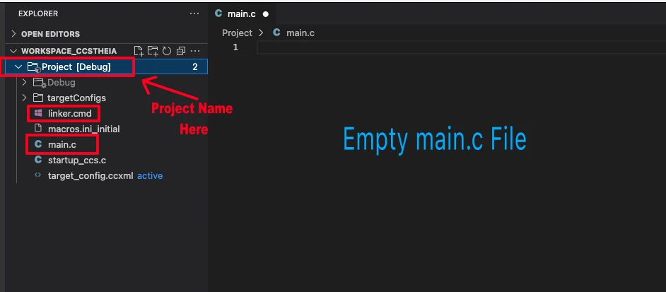
There are only 2 things we need to do to turn the blinky template into a new project:
- Delete everything from the blinky.c file, so it should be completely empty. We will write everything ourselves.
- Rename the following:
- blinky.c → main.c, indicating that this is the main file for the project
- blinky_css.cmd → linker.cmd, indicating that this is the linker file
- blinky (Folder) → projectName (Folder)
The final modified project is shown in the image below.
Including TivaWare Driver Library
To simplify UART configuration, we’ll use the TivaWare driver library, which provides ready-to-use APIs for enabling peripherals and setting up UART communication.
Include the following header files at the top of your program:
#include <stdint.h>
#include <stdbool.h>
#include "inc/hw_memmap.h"
#include "driverlib/sysctl.h"
#include "driverlib/gpio.h"
#include "driverlib/uart.h"
#include "driverlib/pin_map.h"These headers serve the following purpose:
| Header File | Purpose | Example Function |
|---|---|---|
| driverlib/sysctl.h | Controls system clock and peripheral power | SysCtlPeripheralEnable() |
| driverlib/gpio.h | Configures GPIO pins for alternate functions | GPIOPinTypeUART() |
| driverlib/uart.h | Manages UART configuration and data transfer | UARTConfigSetExpClk() |
| driverlib/pin_map.h | Maps GPIO pins to their UART functions | GPIOPinConfigure() |
| inc/hw_memmap.h | Defines base addresses of peripherals | UART0_BASE, GPIO_PORTA_BASE |
Enabling UART Module and Pins
Before using UART interrupts, we need to enable the UART module and configure its pins. Here’s how to do it in TivaWare:
// Initialize UART0 with RX interrupt
void UART0_InterruptInit(void)
{
// Enable UART0 and Port A
SysCtlPeripheralEnable(SYSCTL_PERIPH_UART0);
SysCtlPeripheralEnable(SYSCTL_PERIPH_GPIOA);
// Wait for peripherals to be ready
while(!SysCtlPeripheralReady(SYSCTL_PERIPH_UART0));
while(!SysCtlPeripheralReady(SYSCTL_PERIPH_GPIOA));
// Configure pins for UART0 (PA0=RX, PA1=TX)
GPIOPinConfigure(GPIO_PA0_U0RX);
GPIOPinConfigure(GPIO_PA1_U0TX);
GPIOPinTypeUART(GPIO_PORTA_BASE, GPIO_PIN_0 | GPIO_PIN_1);
// Configure UART clock and baud rate
UARTClockSourceSet(UART0_BASE, UART_CLOCK_PIOSC);
UARTConfigSetExpClk(UART0_BASE, 16000000, 115200,
(UART_CONFIG_WLEN_8 | UART_CONFIG_STOP_ONE | UART_CONFIG_PAR_NONE));
// Register UART0 Interrupt Handler
UARTIntRegister(UART0_BASE, UART0_Handler);
// Enable UART receive interrupt
UARTIntEnable(UART0_BASE, UART_INT_RX | UART_INT_RT); // RX interrupt only
IntEnable(INT_UART0);
// Enable global interrupts
// IntMasterEnable(); // we will do this later in the main function
// Enable UART
UARTEnable(UART0_BASE);
}This function UART0_InterruptInit() initializes UART0 on the TM4C123G microcontroller for serial communication (TX/RX). It configures the interrupt for the RX Mode. It also sets up the required peripherals, pins, and UART configuration so you can send and receive data through the USB (Virtual COM Port).
Line-by-Line Explanation
SysCtlPeripheralEnable(SYSCTL_PERIPH_UART0);
SysCtlPeripheralEnable(SYSCTL_PERIPH_GPIOA);Enables the clock for UART0 and GPIO Port A. UART0 pins (PA0 and PA1) belong to Port A. Without enabling the clock, the peripherals won’t work.
while(!SysCtlPeripheralReady(SYSCTL_PERIPH_UART0));
while(!SysCtlPeripheralReady(SYSCTL_PERIPH_GPIOA));Waits until both peripherals are fully ready to use. This ensures the hardware is powered and initialized before configuration.
GPIOPinConfigure(GPIO_PA0_U0RX);
GPIOPinConfigure(GPIO_PA1_U0TX);
GPIOPinTypeUART(GPIO_PORTA_BASE, GPIO_PIN_0 | GPIO_PIN_1);Configures PA0 as UART0 RX and PA1 as UART0 TX using their alternate functions. This assigns the UART receive and transmit functions to the correct pins.
UARTClockSourceSet(UART0_BASE, UART_CLOCK_PIOSC);Selects the Precision Internal Oscillator (PIOSC) as the UART0 clock source. This is a 16 MHz internal clock, independent of the system clock.
Each UART module can use a different clock source. The clock matters because the baud rate is calculated based on it.
If you choose PIOSC and configure 115200 baud, the timing will be correct. Using a different clock (like PLL-based system clock) without adjusting the baud rate can cause garbled characters.
UARTConfigSetExpClk(UART0_BASE, 16000000, 115200,
(UART_CONFIG_WLEN_8 | UART_CONFIG_STOP_ONE | UART_CONFIG_PAR_NONE));Sets the UART communication format:
- Baud rate: 115200
- Data length: 8 bits
- Stop bits: 1
- Parity: None
UARTIntRegister(UART0_BASE, UART0_Handler);Registers the function UART0_Handler as the Interrupt Service Routine (ISR) for UART0. Whenever a UART0 interrupt occurs, the processor will automatically jump to this function. Using UARTIntRegister() makes it easy to assign your custom ISR without manually editing the vector table.
UARTIntEnable(UART0_BASE, UART_INT_RX | UART_INT_RT);Enables both Receive (RX) and Receive Timeout (RT) interrupts.
UART_INT_RXfires when the receive FIFO reaches its threshold (usually half full, i.e., 8 bytes).UART_INT_RTfires when some data is received but no new data arrives for a short period.
Together, they make sure that the interrupt triggers even for short messages like"RED"or"Hello", improving responsiveness.
IntEnable(INT_UART0);Enables the UART0 interrupt line in the NVIC (Nested Vectored Interrupt Controller). This step connects the UART0 peripheral interrupt to the processor core, allowing it to respond when the event occurs. Without this, the ISR won’t be executed even if UART0 raises an interrupt.
// IntMasterEnable(); // we will do this later in the main functionEnables global interrupts when called. Here, it is commented out because global interrupts will be enabled later in main(), after all peripherals are initialized This ensures that no interrupt fires prematurely while setup is still in progress.
UARTEnable(UART0_BASE);Finally, enables the UART0 module for both transmit and receive operations. At this point, UART0 is fully configured and ready to generate interrupts whenever data is received.
Writing the UART Interrupt Service Routine (ISR)
Now that we have configured the UART interrupts, let’s write the Interrupt Service Routine (ISR) that actually handles the received data. Whenever new data arrives at the UART or a receive timeout occurs, the processor automatically triggers this ISR.
Our goal here is to read the incoming characters quickly, store them in a buffer, and then signal the main loop that new data is available. This keeps the interrupt routine fast and efficient, while the actual data processing can be done safely outside the ISR.
#define RX_BUFFER_SIZE 64
char rxBuffer[RX_BUFFER_SIZE];
volatile uint8_t isRxed = 0;
volatile uint8_t indx = 0;
void UART0_Handler(void)
{
uint32_t status = UARTIntStatus(UART0_BASE, true);
UARTIntClear(UART0_BASE, status);
if ((status & UART_INT_RX) || (status & UART_INT_RT)) // If the RX interrupt is triggered
{
indx = 0;
while(UARTCharsAvail(UART0_BASE)) // check if there are more available characters
{
char data = UARTCharGetNonBlocking(UART0_BASE); // Read data in Non-Blocking manner
rxBuffer[indx++] = data; // store data in the buffer
// if(indx >= RX_BUFFER_SIZE) indx = 0; // Wrap around for circular buffer
isRxed = 1;
}
}
}Whenever the UART0 interrupt occurs (due to RX or timeout), the processor automatically calls this function UART0_Handler().
Line-by-Line Explanation
#define RX_BUFFER_SIZE 64
char rxBuffer[RX_BUFFER_SIZE];
volatile uint8_t isRxed = 0;
volatile uint8_t indx = 0;Defines a buffer and helper variables for UART data handling.
RX_BUFFER_SIZEsets the buffer length (64 bytes).rxBuffer[]stores the received characters temporarily.isRxedacts as a flag to inform the main loop that new data has arrived.indxkeeps track of the current write position in the buffer.- The
volatilekeyword ensures the compiler does not optimize these variables, since they are modified inside the ISR.
uint32_t status = UARTIntStatus(UART0_BASE, true);Reads the current interrupt status of UART0. The true argument ensures it returns only the masked interrupts (those that are both enabled and triggered).
This tells us exactly why the interrupt occurred — for example, due to new data (RX) or a receive timeout (RT).
UARTIntClear(UART0_BASE, status);Clears the interrupt flags that were just read. This is an essential step — without it, the same interrupt would keep triggering repeatedly.
if ((status & UART_INT_RX) || (status & UART_INT_RT))Checks if the interrupt was caused by received data (UART_INT_RX) or by a receive timeout (UART_INT_RT). We handle both together so the ISR works for both full FIFO and short messages.
indx = 0;Resets the buffer index before reading new data. This ensures we start storing from the beginning of rxBuffer for each new message.
while(UARTCharsAvail(UART0_BASE))Checks if there are any more characters available in the UART FIFO. If yes, the loop continues reading until the FIFO is empty. This guarantees that all received characters are read in one go.
char data = UARTCharGetNonBlocking(UART0_BASE);Reads a single character from the UART receive FIFO using a non-blocking function. It immediately returns the character without waiting, ensuring the ISR executes quickly.
rxBuffer[indx++] = data;Stores the received character into the buffer and increments the index. This way, each incoming byte is saved sequentially in rxBuffer.
Optionally, you can enable the circular buffer line (if(indx >= RX_BUFFER_SIZE) indx = 0;) if you expect continuous data reception.
isRxed = 1;Sets the receive flag to indicate that a new message has been received. The main loop can check this flag to process the received data outside the ISR.
Practical Example: Controlling LEDs and Sending Data via UART on TM4C123G
In this section, we’ll create a complete UART communication example on the TM4C123G LaunchPad using interrupts for reception and polling for transmission. The board will receive commands like "RED", "BLUE", or "GREEN" to control LEDs and will periodically send "Hello World" messages over the UART terminal.
This project demonstrates bi-directional UART communication using TivaWare APIs.
Connecting LEDs to GPIO Pins
The TM4C123G board includes three on-board LEDs connected to Port F:
- PF1 – Red LED
- PF2 – Blue LED
- PF3 – Green LED
To use them, we first enable Port F, wait for it to be ready, and configure the pins as output.
SysCtlPeripheralEnable(SYSCTL_PERIPH_GPIOF);
while(!SysCtlPeripheralReady(SYSCTL_PERIPH_GPIOF));
GPIOPinTypeGPIOOutput(GPIO_PORTF_BASE, GPIO_PIN_3 | GPIO_PIN_2 | GPIO_PIN_1);This ensures that all three LEDs are properly configured and ready to be toggled based on UART commands.
Sending Data via UART
Let’s add a simple function to send strings over UART. This function transmits data character by character using UARTCharPut(). Since this is a blocking function, it waits until the transmitter is ready before sending each byte.
void UART0_SendString(const char *str)
{
while(*str)
{
UARTCharPut(UART0_BASE, *str++);
}
}You can use this function anywhere in the code to print messages to your serial terminal — perfect for debugging or status updates.
Parsing Received UART Data
The main loop continuously checks the flag isRxed, which is set inside the UART interrupt handler whenever new data arrives. Once data is received, it is compared with predefined command strings to determine which LED to activate.
if (isRxed == 1)
{
isRxed = 0;
if (strncmp(rxBuffer, "RED", indx) == 0)
GPIOPinWrite(GPIO_PORTF_BASE, GPIO_PIN_1|GPIO_PIN_2|GPIO_PIN_3, GPIO_PIN_1);
else if (strncmp(rxBuffer, "BLUE", indx) == 0)
GPIOPinWrite(GPIO_PORTF_BASE, GPIO_PIN_1|GPIO_PIN_2|GPIO_PIN_3, GPIO_PIN_2);
else if (strncmp(rxBuffer, "GREEN", indx) == 0)
GPIOPinWrite(GPIO_PORTF_BASE, GPIO_PIN_1|GPIO_PIN_2|GPIO_PIN_3, GPIO_PIN_3);
else if (strncmp(rxBuffer, "PINK", indx) == 0)
GPIOPinWrite(GPIO_PORTF_BASE, GPIO_PIN_1|GPIO_PIN_2|GPIO_PIN_3, GPIO_PIN_1|GPIO_PIN_2);
else if (strncmp(rxBuffer, "YELLOW", indx) == 0)
GPIOPinWrite(GPIO_PORTF_BASE, GPIO_PIN_1|GPIO_PIN_2|GPIO_PIN_3, GPIO_PIN_1|GPIO_PIN_3);
else
GPIOPinWrite(GPIO_PORTF_BASE, GPIO_PIN_1 | GPIO_PIN_2 | GPIO_PIN_3, 0);
}Here’s how it works:
- The interrupt handler fills
rxBufferwith incoming characters. - The main loop checks
isRxedand processes the command. - Depending on the text received, the matching LED lights up.
- Any unknown command will turn off all LEDs.
Complete code
The Complete code for this project is shown below. We will transmit the data via UART periodically and use interrupt to receive the data to control the LED.
#include <stdint.h>
#include <stdbool.h>
#include "inc/hw_memmap.h"
#include "driverlib/sysctl.h"
#include "driverlib/gpio.h"
#include "driverlib/uart.h"
#include "driverlib/pin_map.h"
#include "driverlib/interrupt.h"
#include "basic_conf.h"
#include "inc/hw_ints.h"
#include "string.h"
#define RX_BUFFER_SIZE 64
char rxBuffer[RX_BUFFER_SIZE];
volatile uint8_t isRxed = 0;
volatile uint8_t indx = 0;
void UART0_Handler(void);
// Initialize UART0 with RX interrupt
void UART0_InterruptInit(void)
{
    // Enable UART0 and Port A
    SysCtlPeripheralEnable(SYSCTL_PERIPH_UART0);
    SysCtlPeripheralEnable(SYSCTL_PERIPH_GPIOA);

    // Wait for peripherals to be ready
    while(!SysCtlPeripheralReady(SYSCTL_PERIPH_UART0));
    while(!SysCtlPeripheralReady(SYSCTL_PERIPH_GPIOA));

    // Configure pins for UART0 (PA0=RX, PA1=TX)
    GPIOPinConfigure(GPIO_PA0_U0RX);
    GPIOPinConfigure(GPIO_PA1_U0TX);
    GPIOPinTypeUART(GPIO_PORTA_BASE, GPIO_PIN_0 | GPIO_PIN_1);

    // Configure UART clock and baud rate
    UARTClockSourceSet(UART0_BASE, UART_CLOCK_PIOSC);
    UARTConfigSetExpClk(UART0_BASE, 16000000, 115200,
                        (UART_CONFIG_WLEN_8 | UART_CONFIG_STOP_ONE | UART_CONFIG_PAR_NONE));

    // Register UART0 Interrupt Handler
    UARTIntRegister(UART0_BASE, UART0_Handler);

    // Enable UART receive interrupt
    UARTIntEnable(UART0_BASE, UART_INT_RX | UART_INT_RT);    // RX interrupt only

    IntEnable(INT_UART0);

    // Enable global interrupts
    // IntMasterEnable();  // we will do this later in the main function

    // Enable UART
    UARTEnable(UART0_BASE);
}
void UART0_SendString(const char *str)
{
    while(*str)
    {
        UARTCharPut(UART0_BASE, *str++);
    }
}
int main(void)
{
systemClockConfig();
UART0_InterruptInit();
SysCtlPeripheralEnable(SYSCTL_PERIPH_GPIOF);
while(!SysCtlPeripheralReady(SYSCTL_PERIPH_GPIOF));
GPIOPinTypeGPIOOutput(GPIO_PORTF_BASE, GPIO_PIN_3|GPIO_PIN_1|GPIO_PIN_2);
IntMasterEnable();
while(1)
{
if (isRxed == 1)
{
    isRxed = 0;

    if (strncmp(rxBuffer, "RED", indx) == 0)
        GPIOPinWrite(GPIO_PORTF_BASE, GPIO_PIN_1|GPIO_PIN_2|GPIO_PIN_3, GPIO_PIN_1);
    else if (strncmp(rxBuffer, "BLUE", indx) == 0)
        GPIOPinWrite(GPIO_PORTF_BASE, GPIO_PIN_1|GPIO_PIN_2|GPIO_PIN_3, GPIO_PIN_2);
    else if (strncmp(rxBuffer, "GREEN", indx) == 0)
        GPIOPinWrite(GPIO_PORTF_BASE, GPIO_PIN_1|GPIO_PIN_2|GPIO_PIN_3, GPIO_PIN_3);
    else if (strncmp(rxBuffer, "PINK", indx) == 0)
        GPIOPinWrite(GPIO_PORTF_BASE, GPIO_PIN_1|GPIO_PIN_2|GPIO_PIN_3, GPIO_PIN_1|GPIO_PIN_2);
    else if (strncmp(rxBuffer, "YELLOW", indx) == 0)
        GPIOPinWrite(GPIO_PORTF_BASE, GPIO_PIN_1|GPIO_PIN_2|GPIO_PIN_3, GPIO_PIN_1|GPIO_PIN_3);
    else
        GPIOPinWrite(GPIO_PORTF_BASE, GPIO_PIN_1 | GPIO_PIN_2 | GPIO_PIN_3, 0);
}
UART0_SendString("Hello World\r\n");
delay_ms(1000);
}
}
void UART0_Handler(void)
{
uint32_t status = UARTIntStatus(UART0_BASE, true);
UARTIntClear(UART0_BASE, status);
if ((status & UART_INT_RX) || (status & UART_INT_RT)) // If the RX interrupt is triggered
{
indx = 0;
while(UARTCharsAvail(UART0_BASE)) // check if there are more available characters
{
char data = UARTCharGetNonBlocking(UART0_BASE); // Read data in Non-Blocking manner
rxBuffer[indx++] = data; // store data in the buffer
// if(indx >= RX_BUFFER_SIZE) indx = 0; // Wrap around for circular buffer
isRxed = 1;
}
}
}
Result and Demonstration
In this demo, we will send commands like “RED”, “BLUE”, and “GREEN” from a serial terminal (such as PuTTY or Tera Term) to the TM4C123G LaunchPad. Each command will instantly turn on the corresponding LED on the board.
At the same time, the microcontroller will periodically transmit “Hello World” messages back to the terminal, confirming that UART transmission and reception both work perfectly.
The video below demonstrate the real-time LED control via UART interrupts and the continuous UART output on the serial terminal.
Troubleshooting UART Interrupts on TM4C123G
UART interrupts are very reliable once configured correctly, but a few common mistakes can cause them to fail or behave unpredictably. Let’s look at the most frequent issues you might face and how to fix them.
Common Errors and Their Fixes
1. Interrupt Not Triggering
- Make sure you have enabled both the UART interrupt and the NVIC interrupt line:
UARTIntEnable(UART0_BASE, UART_INT_RX | UART_INT_RT); IntEnable(INT_UART0); - Don’t forget to enable global interrupts with
IntMasterEnable()inmain(). - Check that the UART0_Handler is correctly registered using
UARTIntRegister().
2. Receiving Data Only After Multiple Sends
If the interrupt only triggers after sending the same command several times, enable the Receive Timeout interrupt (RT) along with RX:
UARTIntEnable(UART0_BASE, UART_INT_RX | UART_INT_RT);This makes sure even short messages (like "RED") trigger the interrupt correctly.
3. No Output on Terminal
- Verify the baud rate and clock source match your terminal settings.
- Use
UARTClockSourceSet(UART0_BASE, UART_CLOCK_PIOSC);for a stable 16 MHz internal clock. - Check your USB cable connection — many boards require a virtual COM port driver to communicate properly.
Tips to Avoid Garbled or Missing Data
- Always ensure that TX and RX baud rates on both MCU and terminal are the same (e.g., 115200 bps).
- Use the Precision Internal Oscillator (PIOSC) for consistent UART timing.
- Avoid long processing inside the ISR — just store data and set a flag. Process data in the main loop instead.
- If you see missing characters, consider using UART_INT_RT so partial messages still trigger the interrupt.
- Add a small delay (e.g.,
delay_ms(10)) after sending large strings if your terminal can’t handle fast consecutive transmissions.
Conclusion
In this tutorial, you learned how to use UART interrupts on the TM4C123G LaunchPad for efficient data reception. Instead of continuously polling, the interrupt-based method lets the MCU react instantly when new data arrives.
We also built a simple example where UART commands control on-board LEDs, and the board periodically sends “Hello World” messages back to the terminal.
This demonstrated both UART transmission and reception working together in real time.
With UART interrupts now running smoothly, you can easily expand this setup to handle more commands or external modules.
Browse More TM4C123G Tutorials
TM4C123 Clock Configuration: Main Oscillator, PIOSC & PLL with TivaWare
TM4C123G Delay Tutorial – Using SysCtlDelay and SysTick Timer
TM4C123 GPIO Tutorial – Digital Input and Output using Tiva C LaunchPad
TM4C123 GPIO External Interrupts (Using TivaWare in Code Composer Studio)
TM4C123G UART Tutorial (PART 1) – How to Use UART and Virtual COM Port in Tiva C

I2C in TM4C123G Tiva C – How to Use I2C Peripheral with TivaWare
TM4C123G SPI Tutorial: Configure SSI0 & Read ADXL345 with TivaWare
TM4C123G UART Interrupt Project Download
TM4C123G UART Interrupt FAQs

Subscribe
Login
0 Comments
Newest
