Updated On: February 6, 2026
Getting Started with TM4C123G LaunchPad in CCS Studio
The TM4C123G LaunchPad from Texas Instruments is a versatile development board based on the ARM Cortex-M4 microcontroller. It is widely used by students, hobbyists, and professionals to learn embedded systems, experiment with peripherals, and develop real-time applications. The board comes equipped with onboard LEDs, buttons, and a USB interface, making it ideal for hands-on projects and prototyping.

To program and debug the TM4C123G, we use Code Composer Studio (CCS) — a robust Integrated Development Environment (IDE) provided by Texas Instruments. CCS offers a seamless interface for writing, compiling, and debugging code, along with powerful tools to manage microcontroller projects efficiently.
In this tutorial, you’ll learn how to install CCS Studio, set up your workspace, and create your very first project for the TM4C123G LaunchPad. By the end, you’ll have a simple program running on your board, giving you a solid foundation to explore more advanced applications and experiments with this powerful microcontroller.
Installing the Code Composer Studio (CCS)
Before you can start programming the TM4C123G LaunchPad, you need to install Code Composer Studio (CCS) — the official IDE from Texas Instruments. CCS provides all the tools necessary to write, compile, and debug your embedded projects. Follow these steps to get it installed and ready:
Download CCS Studio
- Visit the official Texas Instruments CCS download page: https://www.ti.com/tool/CCSTUDIO
- Choose the latest version compatible with your operating system (Windows, macOS, or Linux).
- Select the Free License option if you’re using it for personal or educational purposes.
Install CCS Studio
- Run the downloaded installer.
- Follow the on-screen instructions to select the installation folder.
- Choose the components to install:
- Default options are sufficient for most beginners.
- Make sure “Code Composer Studio IDE” and “ARM Compiler” are selected.
- Complete the installation process. This may take several minutes depending on your system.
Launch CCS for the First Time
- Open CCS Studio after installation.
- Select a workspace folder (this is where your projects will be saved).
- You can use the default location or choose a custom folder.
- The IDE will open with a welcome screen. You are now ready to create your first project for the TM4C123G LaunchPad.
The IDE works in Windows, Linux and even Mac as well (I am running it on Apple silicon M2).
Connect TM4C123G to the Computer
First we will take a look at how to connect TM4C to the computer. The board comes with an on-board In-Circuit Debug Interface (ICDI), which appears as both a debugger and a virtual COM port over USB. This makes programming and serial communication very convenient. While it works seamlessly on Windows, we’ll still go through the basics here. Simply grab the included micro-USB cable, plug it in, and you’ll be ready to connect.
Quick Hardware Prep
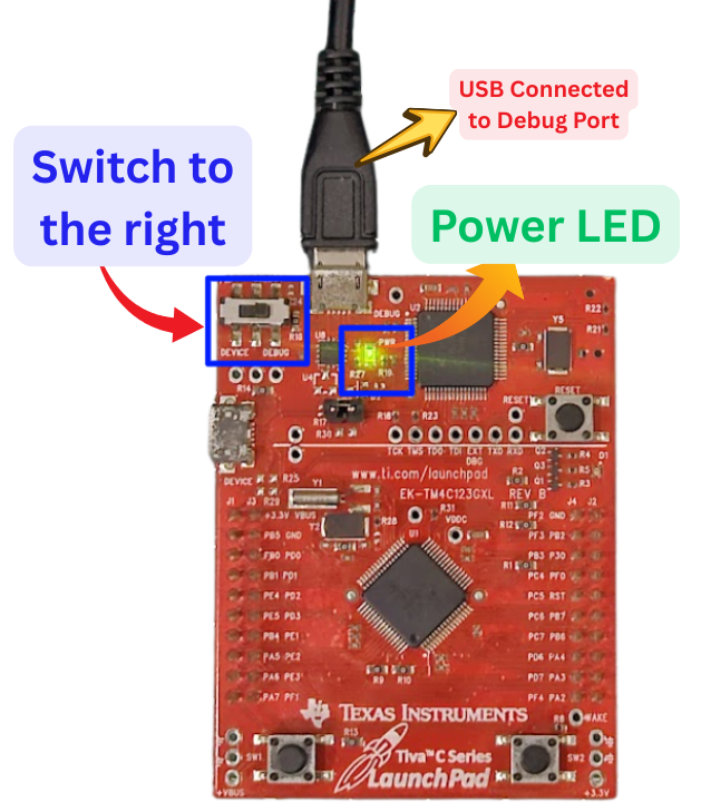
Before drivers, make sure the board’s ready:
- Flip the POWER SELECT switch (SW3) in the top-left corner to DEBUG mode (that’s the right position). This powers the board from the debug USB and enables programming.
- Plug the micro-B end into the DEBUG USB port (the one labeled on the top side, not the device one).
- Connect the USB-A end to your PC. You should see the green POWER LED (D4) light up right away. If not, double-check the switch and cable—could be a dud port.
If the LED’s on but your PC doesn’t recognize it (no sound, no device in Device Manager), time to install the drivers.
Installing ICDI Drivers on Windows
To connect the TM4C123G LaunchPad properly, you need to install TI’s ICDI (In-Circuit Debug Interface) drivers. These drivers are free, lightweight, and work on everything from Windows XP up to Windows 11. Let’s walk through the process step by step.
Note that if the device is showing up in the device manager, you do not need to install the drivers.
Step 1: Download the Stellaris ICDI Drivers
- Go to the official TI ICDI driver download page.
- Download the Stellaris ICDI Drivers ZIP file (around 9 MB).
- Extract the ZIP to an easy-to-find location, such as your Downloads folder.
2: Connect the LaunchPad
- Set your TM4C123G LaunchPad to DEBUG mode.
- Plug it in using the included micro-USB cable.
- Windows may try to install drivers automatically. If you see “Unknown Device” in Device Manager, don’t worry—we’ll fix it manually.
3: Install Drivers Manually
- Open Device Manager (Right-click Start → Device Manager).
- Under Other devices, you should see three entries with yellow exclamation marks (for ICDI).
- For each entry:
- Right-click → Update driver → Browse my computer for drivers.
- Point it to the folder where you extracted the ICDI drivers.
- Check Include subfolders and click Next.
- If you get a warning about unsigned drivers, choose Install anyway (these are safe from TI).
4: Verify Installation
After installation, refresh Device Manager (Right-click → Scan for hardware changes). You should now see:
- Stellaris ICDI JTAG/SWD Interface under Universal Serial Bus devices.
- Stellaris Virtual Serial Port under Ports (COM & LPT). Note down the COM port number—you’ll need it for serial communication tools later.
What About Mac or Linux?
- Mac: The LaunchPad works out of the box with newer Mac versions. After connecting the device check in System Setting → General → About → System Report → Hardware → USB. The Device should be visible here.
- Linux: Usually works with proper udev rules for VID:PID (0x1CBE:0x000C). Plug in the board, run
lsusb, and set permissions. Check TI’s E2E forums for community support.
Troubleshooting Tips
- If drivers won’t install, try unplugging and re-plugging the board, switching USB ports, or using a different cable.
- Restart Windows if the COM port doesn’t appear.
- In rare cases, the ICDI firmware may need an update—TI provides tools for this.
Creating Your First TM4C123G Project in Code Composer Studio
Let’s start by creating a new project in CCStdudio.
Create the project
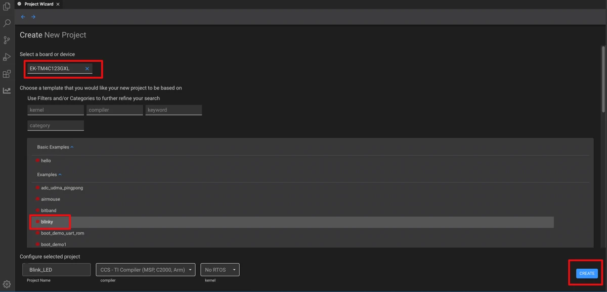
When the IDE runs for the first time, it will show the “Get Started” page. Click on “Create a new project” button to create one.
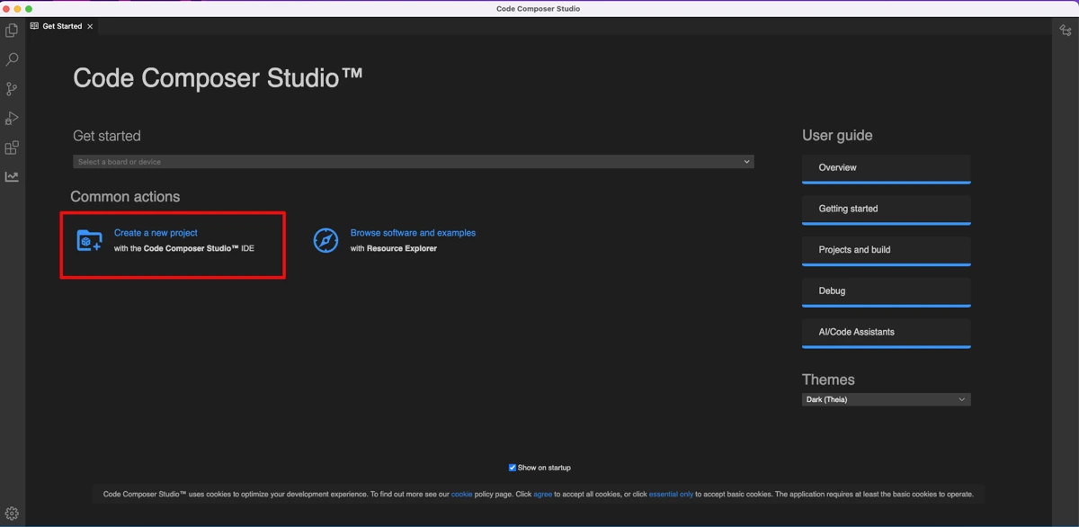
Don’t worry if the IDE does not show this page. You can click on File→Create a new project.
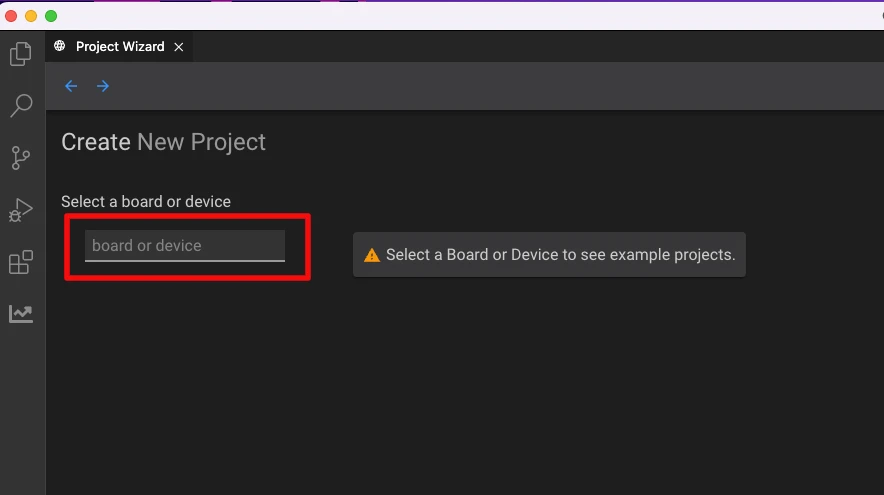
Next, it will ask you to enter the name of the board. Just enter TM4C123G and select the correct board.
Now we need to choose a template project. Let’s select the “blinky” project to blink the LED on board. Click on “Create” button after choosing the project.
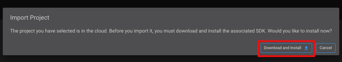
Install the SDK
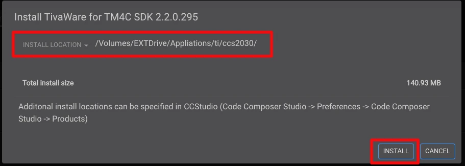
Since this is the first Run, the IDE will ask us to download and install the associated SDK. Just download and install it as shown in the images below.
For clean arrangement, select the install location same as where the IDE is installed.
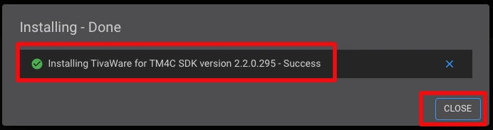
Once the installation is over, you will get the success message as shown below.
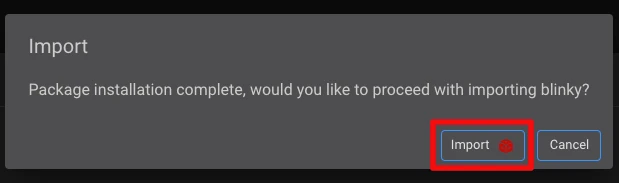
The IDE will now ask you to import the project “blinky”, so just click on the “import” button.
Once the project is imported, you will see the project structure on the left side of the screen, under the workspace tab (Green Box). Open the blinky.c (Red Box), it is the main file for this project.
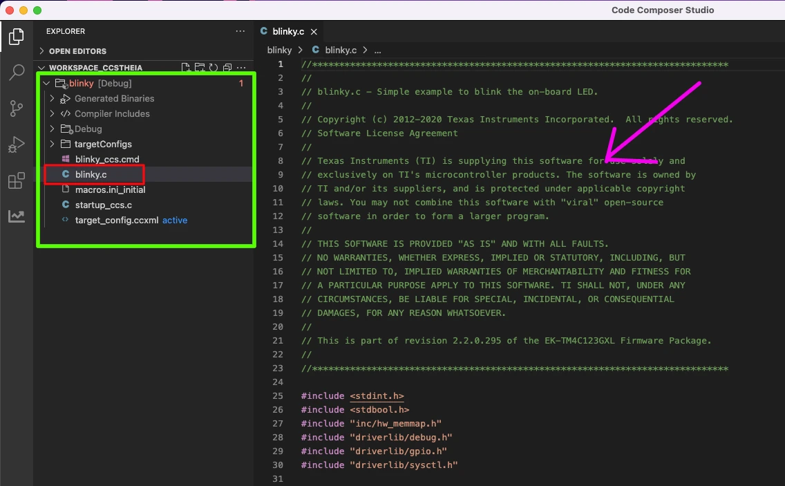
The blinky.c file is opened on the right side of the screen (Pink Arrow). We will write our main code in this file, although this is a template project, hence it already contains the code for blinking the LED.
Build the project
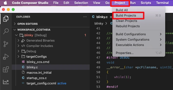
Now click on Project and select Build Project to build the blinky project we just imported. This is just to make sure that there are no errors in the template project.
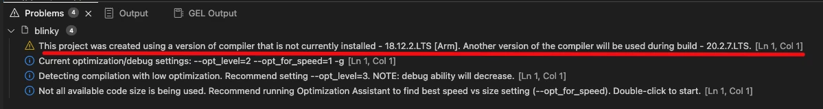
On the bottom of the screen, you will see some errors saying “Buildfile generation error occurred.. This project was created using a version of compiler that is not currently installed – 18.12.2.LTS [Arm]”.
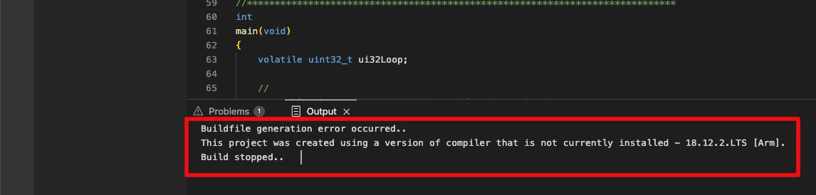
This means that the compiler required to build the project in not installed or not found by the IDE. We are using the TivaWare for TM4C SDK and it requires a specific arm compiler. Therefore we will download the compiler.
Install the Compiler
You can download ARM-CGT compiler from https://www.ti.com/tool/ARM-CGT. Install the compiler in the same location, where the IDE is installed.
Next, open the File → Setting → Code Composer Studio Settings. You should now see the compiler in the list as shown in the image below.
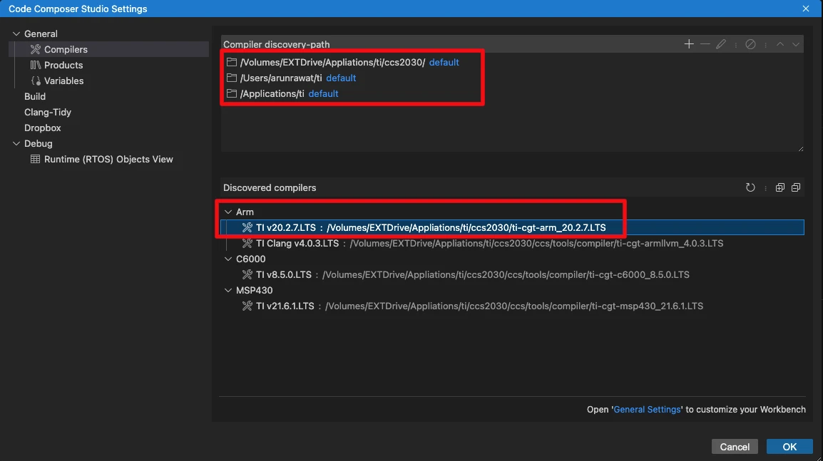
Make sure to install the compiler in one of the compiler discovery-path mentioned above. Note that the compiler version is not exactly 18.12.2.LTS, as the error window requested, but this is a newer version so it will work just fine. If the compiler does not show up, click on the refresh button (First one in the Discovered Compilers Row).
Additional Configuration on windows
If you are using Windows, you might need to do some additional configurations.
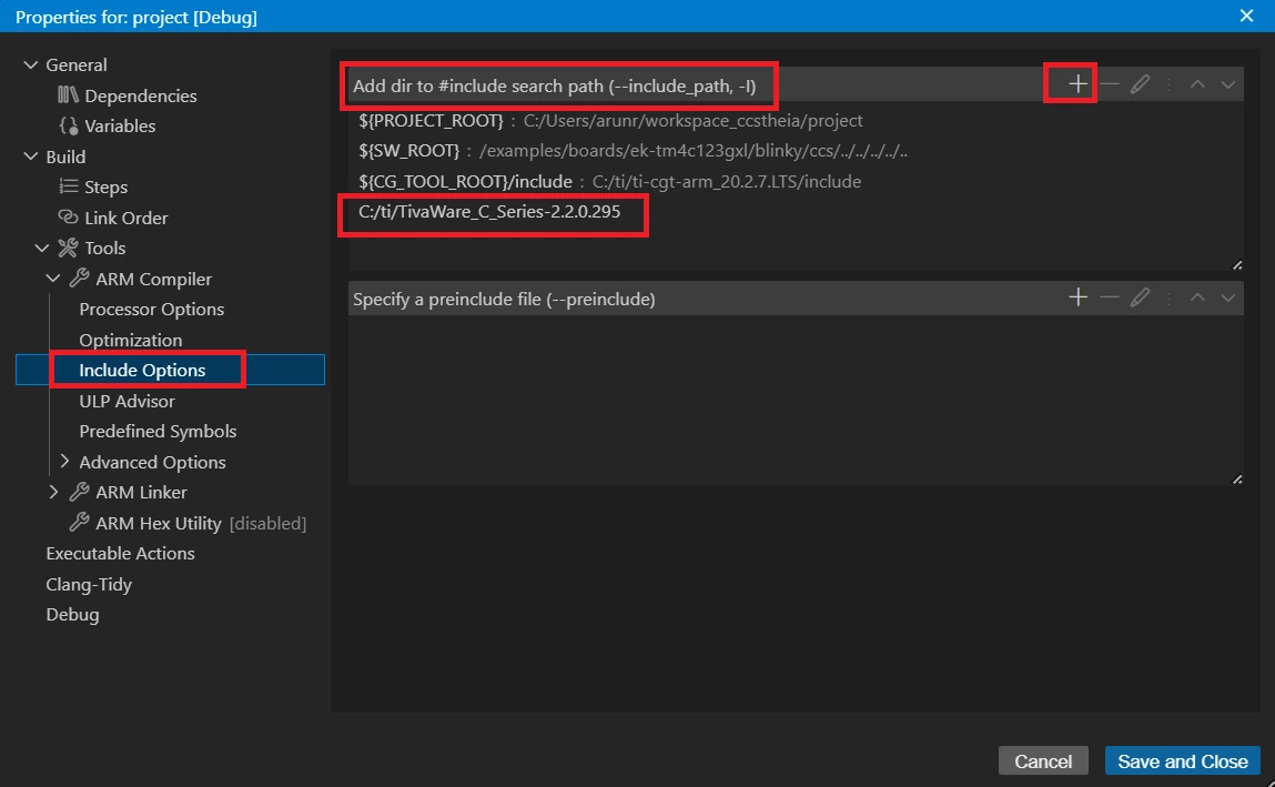
Go to Project Properties -> Tools -> Arm Compiler -> Include Options. Under the #include search path section, include the TivaWare Library Path as shown below:
Next, go to Tools -> ARM Linker -> Search Path. Under the Include library file section, add the path to driverlib.lib file as shown below:
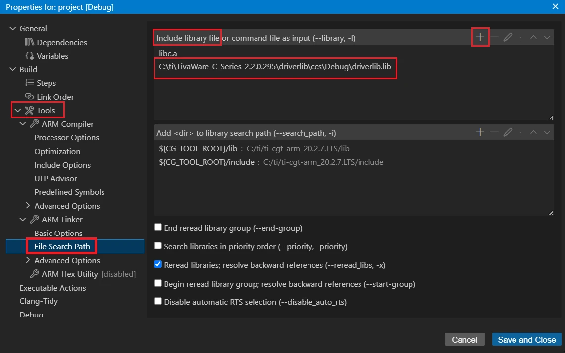
Make sure to delete the existing path to the driverlib.lib file present in this section. Instead add the path shown in the image above.
Build and Flash the project
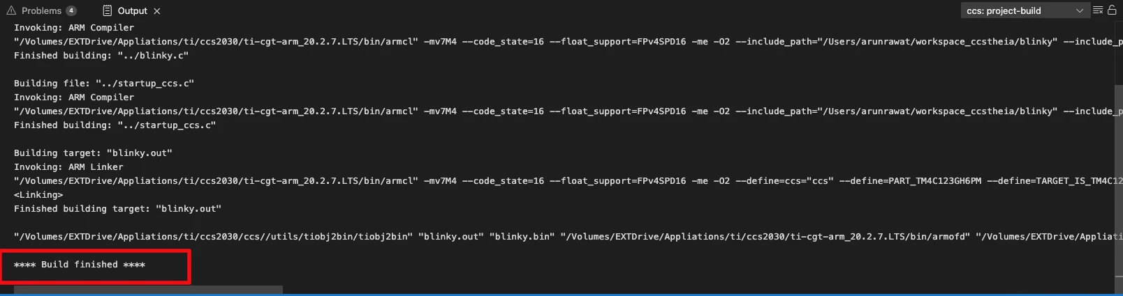
Now build the project again using Project → Build Project and you should see the project builds just fine.
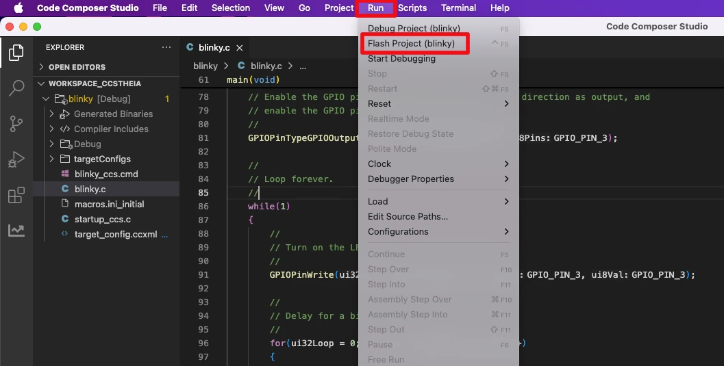
Now it is time to flash the project. Go to Run → Flash Project to flash the “blinky” project to the board.
Once the project is flashed, you should see the LED blinking on the TM4C123G board.
The problem window will still show the error that the exact compiler is not found. But it is fine as we are using a newer version of it.
TM4C123G Code Walkthrough in CCS
Now that we’ve set up Code Composer Studio (CCS) and successfully built our first project, let’s break down the code line by line. This section will help you understand what each part of the program does on the TM4C123G LaunchPad—from including the right header files, configuring the system clock, and setting up GPIO, to writing the main loop logic.
Header Includes
#include <stdint.h>
#include <stdbool.h>
#include "inc/hw_memmap.h"
#include "driverlib/debug.h"
#include "driverlib/gpio.h"
#include "driverlib/sysctl.h"Explanation:
<stdint.h>and<stdbool.h>→ provide standard integer types (uint32_t) andbool."inc/hw_memmap.h"→ contains base addresses for all peripherals (like GPIO ports)."driverlib/debug.h"→ enables debug/error handling support."driverlib/gpio.h"→ functions for configuring and controlling GPIO pins."driverlib/sysctl.h"→ system control functions (clock, power, enabling peripherals).
This shows that the code uses DriverLib APIs (higher-level functions) instead of direct register writes.
Debug Error Handler
#ifdef DEBUG
void
__error__(char *pcFilename, uint32_t ui32Line)
{
    while(1);
}
#endifExplanation:
- Only compiled if
DEBUGis defined. __error__is called when a DriverLib function detects an error.- It traps the MCU in an infinite loop (
while(1);) for debugging. - Useful for catching mistakes during development, but in release builds this is ignored.
Main Function Setup
int
main(void)
{
    volatile uint32_t ui32Loop;

    // Enable the GPIO port that is used for the on-board LED.
    SysCtlPeripheralEnable(SYSCTL_PERIPH_GPIOF);

    // Check if the peripheral access is enabled.
    while(!SysCtlPeripheralReady(SYSCTL_PERIPH_GPIOF))
    {
}Explanation:
main()is where execution starts.ui32Loop→ used later for a crude delay loop.SysCtlPeripheralEnable(SYSCTL_PERIPH_GPIOF)→ turns on the clock for Port F (the LaunchPad LEDs are on Port F).- The
whileloop waits until the peripheral is fully powered and ready.
GPIO Pin Setup
    // Enable the GPIO pin for the LED (PF3).
    // Set the direction as output, and enable the GPIO pin for digital function.
GPIOPinTypeGPIOOutput(GPIO_PORTF_BASE, GPIO_PIN_3);Explanation:
- Configures Pin 3 of Port F (PF3) as a digital output.
- On the TM4C123G LaunchPad, PF3 is the green LED.
- After this, you can control PF3 by writing
1(ON) or0(OFF).
Infinite Loop (Blink Logic)
    while(1)
    {
        // Turn on the LED.
        GPIOPinWrite(GPIO_PORTF_BASE, GPIO_PIN_3, GPIO_PIN_3);

        // Delay for a bit.
        for(ui32Loop = 0; ui32Loop < 200000; ui32Loop++)
        {
        }

        // Turn off the LED.
        GPIOPinWrite(GPIO_PORTF_BASE, GPIO_PIN_3, 0x0);

        // Delay for a bit.
        for(ui32Loop = 0; ui32Loop < 200000; ui32Loop++)
        {
        }
    }
}Explanation:
The while(1) loop runs forever. Here we will call the function GPIOPinWrite to Set or Reset the pin. The parameter of GPIOPinWrite are:
- @ui32Port is the base address of the GPIO port. We use GPIO_PORTF_BASE for Port-F.
- @ui8Pins is the bit-packed representation of the pin(s). Here we define all the pins that this function will control. The
GPIOPinWritefunction will only write to these pins while leaving others. We use the GPIO_PIN_3 for PF3. - @ui8Val is the value to write to the pin(s). A value of 1 for the corresponding pin will Set the pin and a value of 0 will Reset the pin. Here we use GPIO_PIN_3, which is equivalent of using the value 0x00000008, basically a 1 at the PF3 position.
Basically the function GPIOPinWrite(GPIO_PORTF_BASE, GPIO_PIN_3, GPIO_PIN_3); will Set the pin PF3, hence the LED will turn ON.
After setting the pin we will wait for some time, so the LED remains ON for this period. The waiting is performed using for(ui32Loop = 0; ui32Loop < 200000; ui32Loop++){}. Its just a random wait time with the MCU doing nothing while the for loop executes.
Next, we will reset the LED by writing a 0 at the PF3 position in the function GPIOPinWrite(GPIO_PORTF_BASE, GPIO_PIN_3, 0x0);. And there is again a delay loop so the LED remains OFF for this period.
The while loop will run forever and hence we will have the LED blinking effect continuously.
Result: LED Blinking on TM4C123G LaunchPad
When you run the program on your TM4C123G LaunchPad, the green LED (PF3) will start blinking at a steady rate. The LED turns ON when the code writes a logic HIGH to pin PF3, and turns OFF when it writes a logic LOW. The small delay loops between each state make the blink visible to the human eye.
The gif below shows the LED blinking on TM4C123G LaunchPad.

Conclusion
In this tutorial, we successfully set up the TM4C123G LaunchPad, installed the ICDI drivers, and wrote our first program to blink the on-board LED. We explored the code step by step, learned how to enable GPIO ports, configure pins, and toggle the LED using DriverLib functions.
With the LED blinking, you’ve confirmed that your development environment is working correctly and you’re ready to take the next steps in TM4C123G programming.
In the next tutorial, we’ll see how to configure the system clock for the TM4C123G. This is the first step before we can actually start working on the peripherals.
Browse More TM4C123G Tutorials
TM4C123G Delay Tutorial – Using SysCtlDelay and SysTick Timer
TM4C123 GPIO Tutorial – Digital Input and Output using Tiva C LaunchPad
TM4C123 GPIO External Interrupts (Using TivaWare in Code Composer Studio)
TM4C123G UART Tutorial (PART 1) – How to Use UART and Virtual COM Port in Tiva C
TM4C123G UART Tutorial (PART 2): Use Interrupt to Receive Data and Control LEDs

I2C in TM4C123G Tiva C – How to Use I2C Peripheral with TivaWare
TM4C123G SPI Tutorial: Configure SSI0 & Read ADXL345 with TivaWare
TM4C123G LaunchPad blinky Project Download
TM4C123G LaunchPad FAQs

Subscribe
Login
0 Comments
Newest
