Home ▸ STM32 Tutorials ▸
Updated On: June 20, 2026
Interface GC9A01 Round Display with STM32 via SPI & LVGL
Round displays need a round use case, such as smartwatch faces, circular gauges, compact instrument panels, and the GC9A01 delivers a sharp 240×240 IPS pixel output in a 1.28-inch circular footprint that fits all three. Getting it working on STM32 takes SPI configuration, a lightweight display driver, and LVGL wired in correctly. This tutorial covers all three from scratch.
You’ll learn how to interface the 1.28″ GC9A01 round TFT display with an STM32H562 using SPI (with and without DMA), configure LVGL 9.2 in CubeIDE, connect the display flush callback, and run a live LVGL animation example on the circular screen. Part 2 of this series extends this into a full analog clock with SquareLine Studio and STM32 RTC. The complete CubeIDE project is available to download below.
Before starting, familiarity with LVGL on STM32 will help, so check out the LVGL STM32 integration series starting with Part 1 and the STM32 SPI peripheral tutorial if you need a refresher on either. For other OLED and LCD display options, browse the STM32 OLED tutorials and STM32 LCD tutorials collections.
GC9A01 Round Display Overview
The GC9A01 is a round TFT LCD driver IC paired with a 1.28-inch circular IPS panel at 240×240 pixels. Unlike rectangular displays, its fully circular active area makes it a natural fit for any embedded project where the physical form factor is part of the design, for example: watch faces, dial indicators, compact HMIs.
Key Specifications
| Feature | Specification |
|---|---|
| Panel size | 1.28 inch circular |
| Resolution | 240 × 240 pixels |
| Panel type | IPS (wide viewing angle) |
| Color depth | 65K (16-bit) / 262K (18-bit) |
| Interface | SPI |
| Supply voltage | 3.3 V |
| Pixel density | ~260 PPI |
IPS technology gives it wide viewing angles and accurate color reproduction — the 240×240 pixel grid renders sharp icons, gauge needles, and text even at this small size.
Typical Embedded Applications
- Smartwatches and fitness trackers
- Industrial meters and dials (e.g., circular progress indicators)
- Custom HMIs for appliances
- Retro gaming devices with circular screens
- Medical instruments with compact graphical displays
- User interfaces in robotics or drones
GC9A01 Wiring & Hardware Requirement
This tutorial uses the WeAct Studio STM32H562RGT6 development board. The board has 1 MB Flash and 640 KB SRAM, which comfortably handles the LVGL framebuffer and display driver alongside application code.
Any STM32 board will work, with two requirements:
- ≥ 512 KB Flash — LVGL’s compiled library takes up significant code space.
- ≥ 20–30 KB free SRAM — needed for the LVGL draw buffer. Tighter RAM is workable with smaller partial-render buffers, but frame rate will drop.
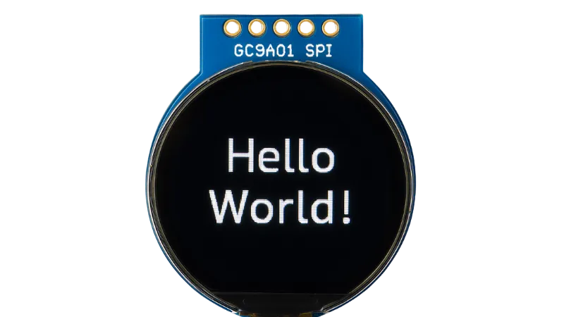
The display used is the 1.28-inch GC9A01 Round TFT LCD Display Module (available from the ControllersTech shop).
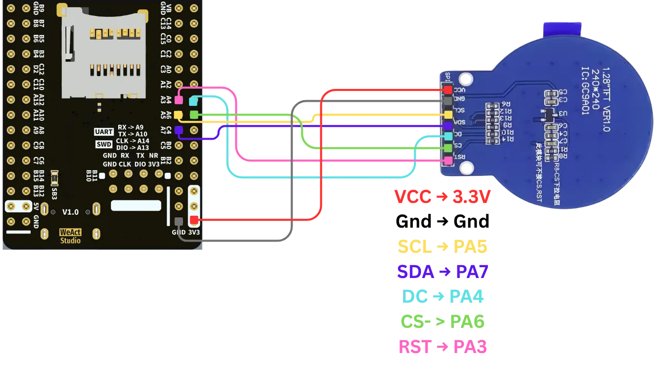
Wiring GC9A01 to STM32 via SPI
The GC9A01 uses a 4-wire SPI interface plus three GPIO control lines (DC, CS, RST). No MISO line is required as the display only receives data.
Connection Table
| GC9A01 Pin | Function | STM32H5 Pin |
|---|---|---|
| VCC | Power Supply | 3.3 V |
| GND | Ground | GND |
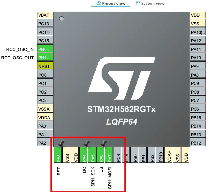
| SCL | SPI Clock | PA5 |
| SDA | SPI Data (MOSI) | PA7 |
| DC | Data/Command Select | PA4 |
| CS | Chip Select | PA6 |
| RST | Reset | PA3 |
PA4 (DC), PA6 (CS), and PA3 (RST) are configured as GPIO Outputs in CubeMX and driven manually in the display driver, they are not SPI peripheral pins.
CubeMX Setup for GC9A01 & LVGL
Clock Configuration
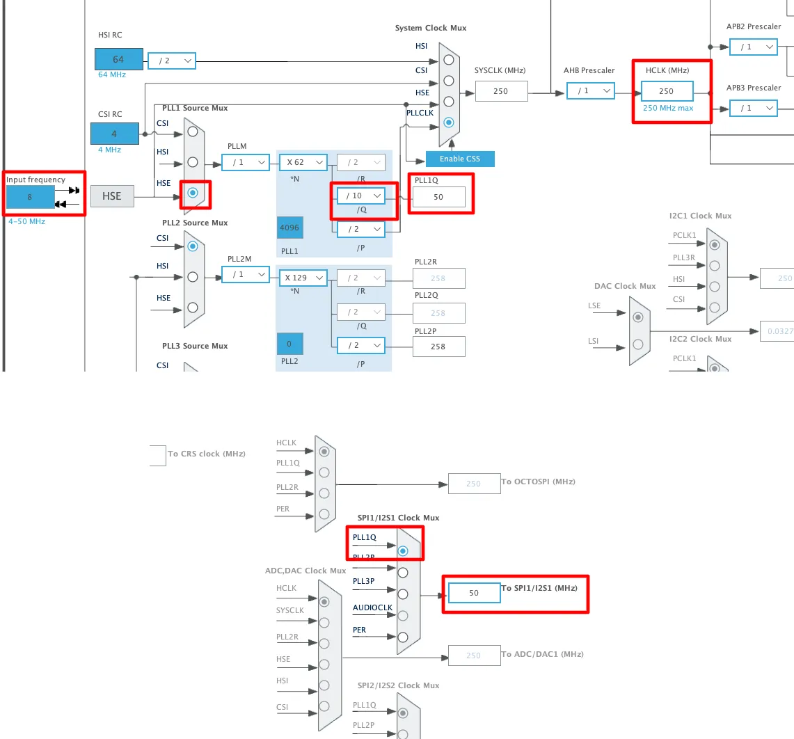
The STM32H562 is clocked from an 8 MHz HSE crystal and runs at the maximum 250 MHz system clock. Adjust PLL1Q to bring the SPI clock source down to 50 MHz before the SPI prescaler is applied.
SPI1 Parameters
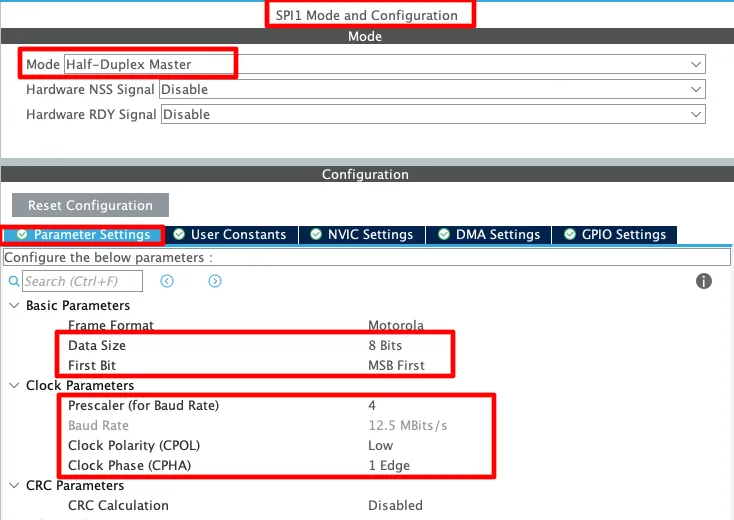
Enable SPI1 in CubeMX and configure:
- Mode: Half Duplex Master — transmit-only; the display sends nothing back.
- Data Size: 8 bits, MSB first.
- Prescaler: 4 → SPI clock = 12.5 MHz (50 MHz ÷ 4). This is a safe, display-compatible clock rate.
- CPOL: Low, CPHA: 1 Edge (SPI Mode 0).
SPI DMA Configuration (Optional)
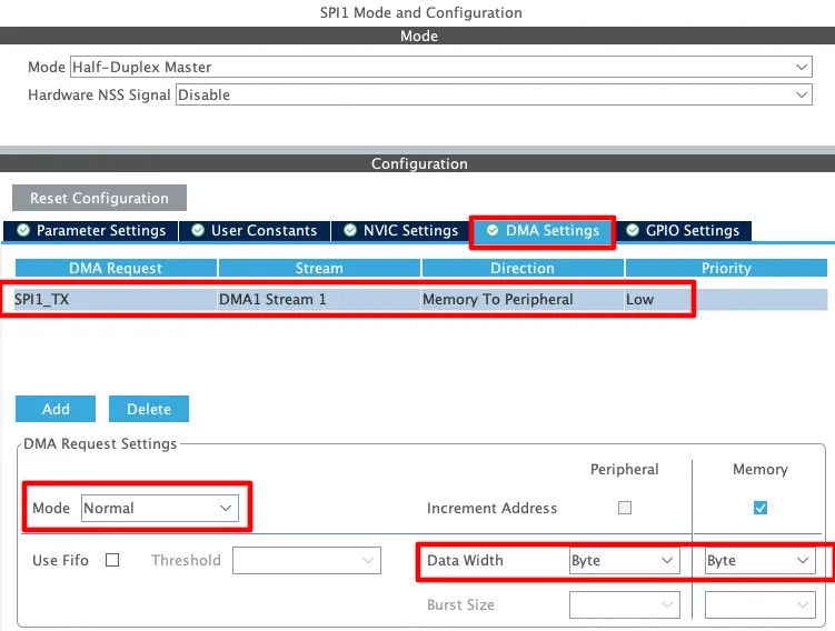
DMA offloads SPI pixel transfer from the CPU, allowing lv_timer_handler() to run concurrently with display flushing and improving frame rate significantly. To enable it:
- Add a DMA request for SPI1 TX.
- Direction: Memory to Peripheral.
- Mode: Normal.
- Data width: Byte.
Set USE_DMA 1 in GC9A01.h after enabling this (see the driver setup section below). If you skip DMA, blocking SPI transmit is used. It is functional, but slower for full-frame animations.
GPIO Pin Configuration
CubeMX auto-assigns PA5 (SCK) and PA7 (MOSI) to SPI1. Manually configure the remaining three pins:
- PA3 → GPIO Output, label:
RST - PA4 → GPIO Output, label:
DC - PA6 → GPIO Output, label:
CS
Matching the label names in CubeMX to the GC9A01_CS_PORT / DC_PORT / RST_PORT defines in GC9A01.h avoids manual pin-name mismatches in generated code.
GC9A01 Driver & LVGL Integration
Adding the GC9A01 Library
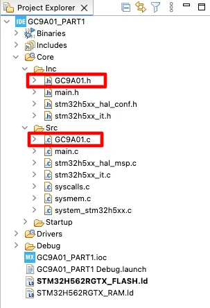
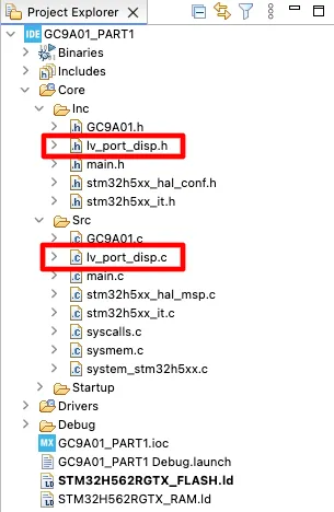
Copy GC9A01.c into the project’s Src folder and GC9A01.h into the Inc folder. The project structure should look like:
Open GC9A01.h and configure the User Configuration block to match your wiring:
// ==== USER CONFIGURATIONS ====
#define GC9A01_SPI           hspi1
#define GC9A01_SPI_TIMEOUT   100
#define USE_DMA              0      // set to 1 if DMA is enabled in CubeMX

#define GC9A01_CS_PORT       GPIOA
#define GC9A01_CS_PIN        GPIO_PIN_6

#define GC9A01_DC_PORT       GPIOA
#define GC9A01_DC_PIN        GPIO_PIN_4

#define GC9A01_RST_PORT      GPIOA
#define GC9A01_RST_PIN GPIO_PIN_3Nothing else in GC9A01.c needs to be modified. All display initialization, pixel-area writes, and flush functions are handled internally by the library.
Installing LVGL 9.2
Download LVGL v9.2 as a ZIP from the LVGL GitHub release branch.
Why v9.2? SquareLine Studio (used in Part 2 of this series) currently targets LVGL 9.2. Using a newer LVGL release will cause API mismatches when importing SquareLine-generated UI files.
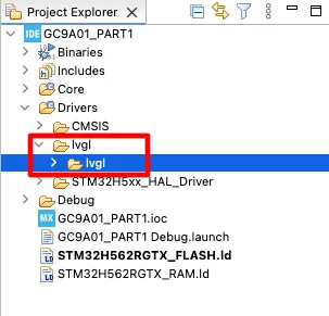
After extracting, rename the folder to lvgl. Create a lvgl subfolder inside your project’s Drivers directory and copy the extracted folder into it:
Configuring lv_conf.h
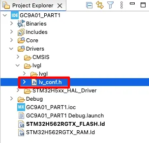
Copy lv_conf_template.h from inside the extracted LVGL folder and paste it beside the lvgl folder (not inside it):
Open lv_conf.h and change line 1 from:
#if 0 /* Set it to "1" to enable content */to:
#if 1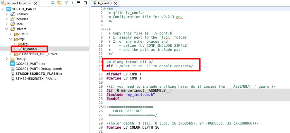
This enables the configuration file. Without this change, LVGL uses its internal defaults and ignores your lv_conf.h entirely.
Adding the Include Path
Right-click the project → Properties → C/C++ Build → Settings → MCU GCC Compiler → Include Paths. Click Add → Workspace, browse to the lvgl folder inside Drivers, and click OK → Apply and Close.
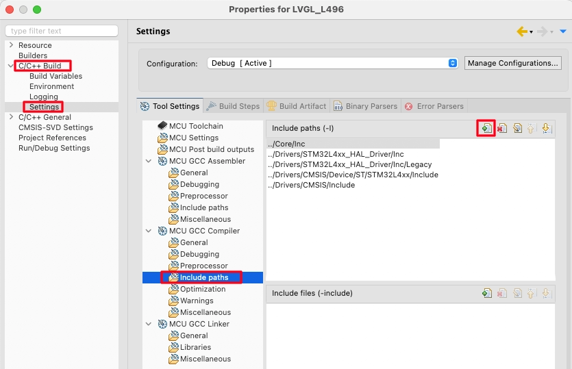
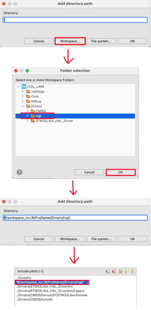
This allows #include "lvgl/lvgl.h" to resolve correctly across all source files.
Connect the Display Driver to LVGL
LVGL communicates with the physical display through a port layer — a pair of files you adapt from LVGL’s built-in template.
Copy from lvgl/examples/porting/:
lv_port_disp_template.c→ Src/lv_port_disp.clv_port_disp_template.h→ Inc/lv_port_disp.h
Display Resolution (lv_port_disp.h)
Open lv_port_disp.h and set the GC9A01’s resolution:
#define MY_DISP_HOR_RES    240
#define MY_DISP_VER_RES 240Display Initialization (lv_port_disp_init)
In lv_port_disp.c, the lv_port_disp_init() function wires LVGL to your hardware. The key modifications are:
lv_display_t *myDisplay = NULL;

void lv_port_disp_init(void)
{
    disp_init();   // initialize GC9A01 hardware

    lv_display_t *disp = lv_display_create(MY_DISP_HOR_RES, MY_DISP_VER_RES);
    lv_display_set_flush_cb(disp, disp_flush);
    myDisplay = disp;

    // Two partial render buffers — 10 rows each
    LV_ATTRIBUTE_MEM_ALIGN
    static uint8_t buf_2_1[MY_DISP_HOR_RES * 10 * BYTE_PER_PIXEL];

    LV_ATTRIBUTE_MEM_ALIGN
    static uint8_t buf_2_2[MY_DISP_HOR_RES * 10 * BYTE_PER_PIXEL];

    lv_display_set_buffers(disp, buf_2_1, buf_2_2,
                           sizeof(buf_2_1), LV_DISPLAY_RENDER_MODE_PARTIAL);
}The disp_init() function calls GC9A01_Init():
static void disp_init(void)
{
    GC9A01_Init();
}Two partial render buffers of 10 rows each (240 × 10 × 2 bytes = 4.8 KB each) are allocated. LVGL renders into one buffer while the other is being flushed to the display — this is the recommended double-buffered partial mode for SPI displays. Increasing the buffer size (e.g., 20 rows) improves frame rate at the cost of more SRAM.
Flush Callback (disp_flush)
LVGL calls disp_flush() each time a region of the framebuffer is ready to send to the display:
static void disp_flush(lv_display_t *disp_drv, const lv_area_t *area, uint8_t *px_map)
{
    if (disp_flush_enabled) {
        // Swap RGB565 byte order for SPI displays
        lv_draw_sw_rgb565_swap(px_map,
            (area->x2 - area->x1 + 1) * (area->y2 - area->y1 + 1));

        GC9A01_Flush(px_map, area->x1, area->y1, area->x2, area->y2);
    }
}lv_draw_sw_rgb565_swap() corrects the byte order of LVGL’s RGB565 pixel data before sending over SPI — required because STM32 SPI transmits in big-endian order but LVGL renders in little-endian. If colours appear wrong on your display, comment this line out and re-test.
GC9A01_Flush() sets the GC9A01’s write window to the area coordinates and transmits all pixel bytes via SPI (blocking or DMA depending on USE_DMA).
Flush Ready Callback (GC9A01_FlushReady)
LVGL must be told when the SPI transfer is complete so it can prepare the next buffer. GC9A01_FlushReady() is declared __weak in the driver — override it in lv_port_disp.c:
void GC9A01_FlushReady(void)
{
    lv_display_flush_ready(myDisplay);
}When using blocking SPI (USE_DMA 0), GC9A01_Flush() calls GC9A01_FlushReady() internally at the end of the transfer. When using DMA (USE_DMA 1), this callback fires from the SPI DMA transfer-complete interrupt, allowing LVGL rendering and SPI transmission to overlap.
SysTick Handler & Main Loop
Open stm32h5xx_it.c (or your series’ equivalent interrupt file) and add to the SysTick handler:
#include "lvgl/lvgl.h"    // add at top of file

void SysTick_Handler(void)
{
    /* USER CODE BEGIN SysTick_IRQn 0 */
    lv_tick_inc(1);       // increment LVGL internal tick by 1 ms
    /* USER CODE END SysTick_IRQn 0 */
    HAL_IncTick();
}lv_tick_inc(1) advances LVGL’s internal millisecond counter, which drives all animation timings, transition durations, and timer callbacks. Without it, animations freeze and LVGL timers never fire.
In main(), initialize LVGL and the display driver before the while loop, then call lv_timer_handler() inside it:
lv_init();              // initialize LVGL
lv_port_disp_init();   // initialize display and connect to LVGL

while (1)
{
    lv_timer_handler(); // process LVGL events and render pending frames
    HAL_Delay(5);       // yield ~5 ms between handler calls
}lv_timer_handler() does all the work: it checks which screen regions are dirty, calls disp_flush() for each, runs widget animations, and processes LVGL timers. The 5 ms delay gives LVGL a consistent tick budget and prevents the handler from starving other tasks.
Testing with an LVGL Animation
main() Code
LVGL ships with built-in example code. The animation example 2 (lv_example_anim_2) runs a bouncing ball — a quick, self-contained check that SPI, LVGL, color rendering, and the flush pipeline are all working:
#include "lv_port_disp.h"
#include "lvgl/examples/anim/lv_example_anim.h"

int main(void)
{
    // ... HAL_Init, SystemClock_Config, MX_SPI1_Init, MX_GPIO_Init ...

    lv_init();
    lv_port_disp_init();
    lv_example_anim_2();    // start the bouncing ball animation

    while (1)
    {
        lv_timer_handler();
        HAL_Delay(5);
    }
}lv_example_anim.h is located at lvgl/examples/anim/lv_example_anim.h — the path must be reachable from your include paths, which it will be once the LVGL Drivers path is added. No additional source files need to be compiled; the example function is declared in the header and defined in the corresponding .c file within the examples folder.
Result

The ball animation runs on the round display as shown in the LVGL documentation example. The red color confirms that lv_draw_sw_rgb565_swap() is correctly handling byte-order endianness — if the ball appeared blue or cyan instead of red, it would indicate the swap is needed but absent (or vice versa).
STM32 GC9A01 Round Display + LVGL — Video Tutorial
Watch the complete walkthrough: SPI and DMA configuration in CubeMX, wiring the GC9A01 to STM32H562, adding the GC9A01 driver, integrating LVGL 9.2, connecting the display flush pipeline, and running an LVGL animation on the 1.28-inch round display.
STM32 GC9A01 + LVGL: FAQs
Conclusion
Getting the GC9A01 running with LVGL on STM32 involves four distinct layers: the SPI hardware (configured in CubeMX), the display driver (GC9A01.c), the LVGL port layer (lv_port_disp.c), and the SysTick + main-loop plumbing. Each layer is small and self-contained — once you understand what disp_flush() and GC9A01_FlushReady() do, the entire pipeline makes sense and is straightforward to adapt for any other SPI display.
The animation test confirms the full stack is healthy: SPI transmitting, color byte order correct, LVGL tick advancing, and the flush callback closing the loop. From here the display is a blank canvas for LVGL widgets, charts, and animations.
Part 2 of this series takes this foundation and builds a real-time analog clock face using SquareLine Studio for the UI layout and the STM32 RTC peripheral for the time source — exactly the kind of application the GC9A01's round screen is made for. Head to Part 2: Analog Clock on GC9A01 with STM32 + LVGL + SquareLine Studio to continue.
Download the complete CubeIDE project below — it includes GC9A01.c/.h, the configured lv_port_disp.c/.h, lv_conf.h, and the main.c with the LVGL animation example.
Download STM32 GC9A01 + LVGL Project Files (Part 1)
Complete CubeIDE project for STM32H562 — includes GC9A01.c/.h driver, configured lv_port_disp.c/.h, lv_conf.h, and main.c with LVGL animation example. Free to download — support the work if it helped you.
Browse More STM32 Display Tutorials
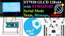
GLCD 128×64 ST7920 interfacing with STM32

Interface 16×2 LCD with STM32 (No I2C) — 4-bit Guide
Custom characters in LCD 1602 || STM32
Interface I2C-LCD1602 (AIP31068) with STM32
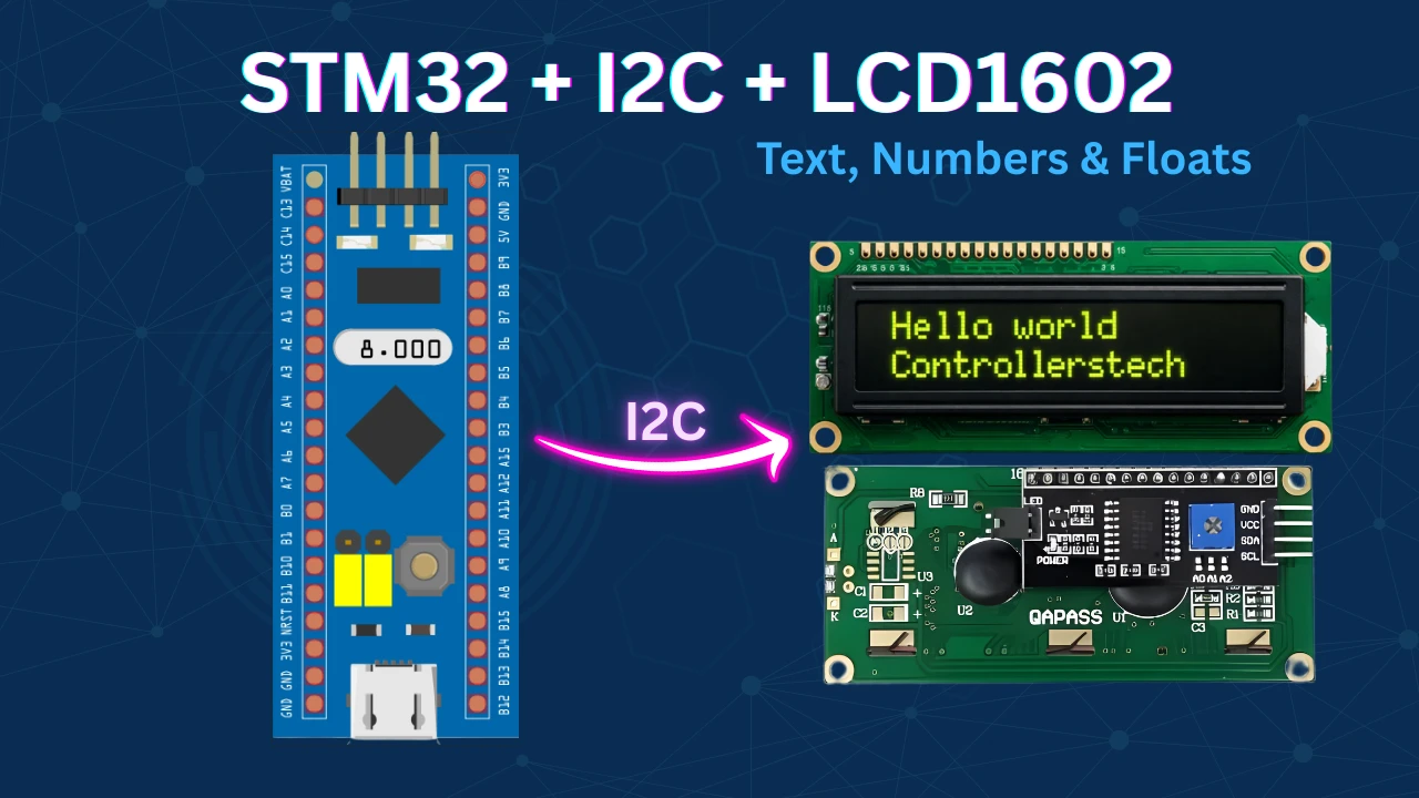
STM32 I2C LCD1602 with PCF8574 — HAL & CubeIDE Tutorial

Subscribe
Login
0 Comments
Newest
