Updated On: February 8, 2026
How to Communicate using Single Wire (Half Duplex Mode)
UART communication typically uses two separate pins—one for transmitting data and another for receiving it. However, in some applications, reducing pin count or wiring complexity is important. For such cases, STM32 provides single-wire (half-duplex) UART communication, where both transmission and reception take place over a single pin.
In this tutorial, we will learn how to configure UART in half-duplex mode on STM32 using CubeMX and HAL. You will see how two STM32 devices can communicate using just one wire by switching between transmit and receive modes. We’ll also cover how interrupts are used to receive data efficiently, making this approach suitable for simple communication setups where devices take turns sending data.
This is the 6th tutorial in the series on the UART peripheral of STM32 Microcontrollers. In this series we will cover different ways of transmitting and receiving data over the UART protocol. We will also see different UART modes available in the STM32 microcontrollers and how to use them.
In this tutorial we will cover the Half Duplex Communication between two STM32 MCUs. Both the MCUs will be put in the Receiver mode. We will use some kind of trigger signal to make one of the MCU as the transmitter and send data to another MCU. This way there will be only one transmitter on the line at a time.
What Is Half-Duplex UART Mode?
In half-duplex UART mode, a single data line is shared for both transmission and reception. At any given time, the microcontroller can either transmit or receive data—but not both simultaneously. The STM32 switches the UART peripheral between transmit mode and receive mode, allowing two devices to communicate by taking turns on the same wire.
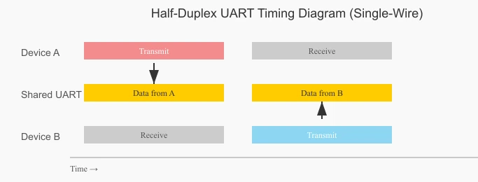
The timing diagram below shows how half-duplex UART communication works. Only one device transmits at a time, while the other remains in receive mode. Both devices alternate between transmit and receive on the same data line.
Advantages of Using Half-Duplex Mode
- Reduced pin count – Only one data pin is required instead of separate TX and RX pins.
- Simpler wiring – Ideal for compact designs or communication over long cables.
- Lower hardware cost – Fewer pins and traces reduce overall system complexity.
- Suitable for master-slave communication – Works well when devices transmit one at a time.
The table below summarises the differences between Hal-Duplex and Full-Duplex UART Modes.
| Feature | Half-Duplex UART | Full-Duplex UART |
|---|---|---|
| Data Lines | Single shared line | Separate TX and RX lines |
| Simultaneous TX/RX | Not possible | Possible |
| Pin Usage | Lower | Higher |
| Wiring Complexity | Simple | More complex |
| Typical Use Case | Turn-based communication | Continuous two-way communication |
| STM32 Configuration | Requires mode switching | Fixed TX and RX roles |
Wiring Diagram for Half-Duplex Mode
To show the Half-Duplex communication, I will use 2 of the STM32 dev boards. They both will be connected using single wire. The image below shows the connection between the two STM32 controllers.
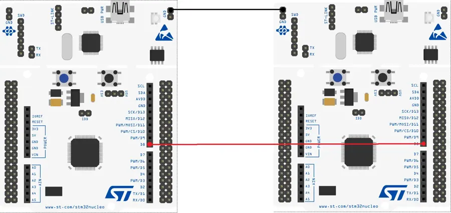
The pin PA9 (D8) is the TX pin for the USART1. Both the TX pins are connected together.
The User Button (Blue) on both the boards will be used as the trigger signal to send the data over the UART. We will configure this button as the input pin in the cubeMX.
Note:
If you are using different power sources for both the MCUs, make sure to give them a common ground. Just connect either of the Ground pins of each MCU together.
STM32 CubeMX Configuration
Below is the image showing the cubeMX configuration for the USART1.
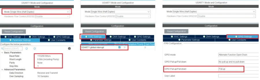
The UART is enabled with the default configuration. The baud rate of 115200 with 1 stop bit and no parity.
I am enabling the interrupt to receive the data in the interrupt mode.
Also make sure to enable the Pull-UP for the TX pin (PA9). This is needed to receive the data.
Note:
Some of the MCUs (Like F103C8) do not have the Pull-up option here, so connect an external pull-up resistor to this TX line.
The User button on the Nucleo-F446 is connected to the pin PC13. I have configured this pin as the External Interrupt (EXTI).
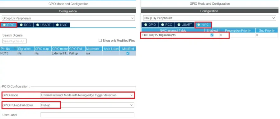
The pin is configured in the Pull-up mode, so initially it will be HIGH. When the button is pressed, the pin will be pulled low to the ground. When the button is released, it will be pulled HIGH again.
The trigger is set to the rising edge and hence it will generate an interrupt when the pin is released. Make sure to enable the interrupt in the NVIC Tab.
STM32 HAL Code for UART Half-Duplex Mode
The same code is used on both the microcontrollers. You can modify the data to be sent, so that it is easier to identify which MCU is sending it.
int main ()
{
  .....
  HAL_HalfDuplex_EnableReceiver(&huart1);
  HAL_UARTEx_ReceiveToIdle_IT(&huart1, RxData, 30);
.....Initially we will put both the MCUs in the Receiver mode, so the function HAL_HalfDuplex_EnableReceiver is used to do that. I am using the Receive to IDLE function to receive 30 bytes of data in the interrupt mode.
When all 30 bytes has been received or an IDLE line is detected before that, the Rx Event Callback will be called.
void HAL_UARTEx_RxEventCallback(UART_HandleTypeDef *huart, uint16_t Size)
{
	HAL_UARTEx_ReceiveToIdle_IT(&huart1, RxData, 30);
}Inside the callback we will call the receive to idle function again so to maintain the continuity in the reception.
When the button is pressed on the nucleo board, the external interrupt is triggered and the EXTI callback is called.
int ispressed = 0;
int indx = 0;
void HAL_GPIO_EXTI_Callback(uint16_t GPIO_Pin)
{
	if (GPIO_Pin == GPIO_PIN_13)
	{
		if (ispressed == 0)
		{
			ispressed = 1;
		}
	}
}Inside the callback we will first check if it is triggered by the pin PC13. Then we will check the value of ispressed variable. If the value is 0, we will set the variable to 1. This indicates that the button has been pressed.
We will send the data in the while loop. The sending process will be protected by the ispressed variable.
  while (1)
  {
	  if (ispressed == 1)
	  {
		  HAL_Delay(500);
		  indx++;
		  int len = sprintf((char*)buffer, "Hello from F446--%d\n", indx);
		  HAL_HalfDuplex_EnableTransmitter(&huart1);
		  HAL_UART_Transmit(&huart1, buffer,len,1000);
		  HAL_HalfDuplex_EnableReceiver(&huart1);
		  ispressed=0;
	  }
}The transmit code will only execute when the ispressed variable is set to 1, which means when the button is pressed.
Here we will first give a small delay so that we can prevent the button debouncing. The indx variable in incremented each time the button is pressed.
We will store the string to be sent in a buffer. The string will always contain an updated value of the indx variable. After storing the string, we will put the MCU in the transmitter mode, then send the data via the UART and put the MCU back to the Receiver mode.
Also reset the ispressed variable so that this loop doesn’t run again until the button is pressed.
Result of STM32 Half-Duplex Communication
The same code is used on both the MCUs. I have just changed the string, so that it is easier to identify which MCU has sent it.
Below is the image showing the result of the above code.
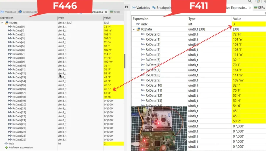
You can see the index value of F411. The data received by the F446 has the same index value in it. This means the updated data has been received by the another MCU.
You can check out the video to see the detailed working.
Video Tutorial
STM32 Single-Wire UART Communication – Video Tutorial
This video walks through half-duplex (single-wire) UART communication on STM32, where the same pin is used for both transmit and receive. You’ll see the complete CubeMX configuration, direction control, and HAL code needed to switch safely between TX and RX without data collision.
Watch the VideoConclusion
Single-wire UART communication on STM32 is a practical solution when pin availability is limited or when simpler wiring is required. By using half-duplex mode, the same UART line can be shared for both transmission and reception, making it ideal for compact designs and controlled, turn-based communication. With proper configuration in CubeMX and careful switching between TX and RX modes, STM32 handles half-duplex communication reliably and efficiently.
Understanding how and when to switch the UART direction is the key to avoiding data collisions and missed bytes. Once this concept is clear, half-duplex UART becomes just as predictable as full-duplex communication. This technique is especially useful in embedded systems where hardware resources are constrained, and it forms a solid foundation for building robust single-wire communication protocols on STM32.
Browse More STM32 UART Tutorials
STM32 UART Part 3 – Receive Data in Blocking & Interrupt mode
STM32 UART DMA Receive: Normal & Circular Mode (HAL)
STM32 UART Idle Line: Receive Data via Interrupt & DMA
STM32 UART Part 7 – How to use one-Wire Protocol
STM32 UART Part 8 – LIN Communication Tutorial
STM32 UART Part 9 – LIN Transceiver Connections & Master-Slave Communication
STM32 UART PART 10 – Lin Protocol PART 3
UART Half-Duplex Project Download
STM32 UART Half-Duplex FAQs

Subscribe
Login
0 Comments
Newest
