Published: November 7, 2025
Last Updated: February 6, 2026
Last Updated: February 6, 2026
STM32 W5500 Ethernet Tutorial Part 2 – TCP Server in Blocking Mode
This is Part 2 of our STM32 W5500 Ethernet tutorial series. In the previous part, we learned how to connect the W5500 Ethernet module to the STM32 microcontroller, configure it using SPI, and perform a successful ping test in both DHCP and Static IP modes.
In this tutorial, we’ll take the next step and create a TCP server on STM32 using the W5500 module.
This server will receive data from a TCP client in blocking mode, echo it back, and then use that received data to perform real microcontroller operations, such as turning an LED ON or OFF.
By the end of this guide, you’ll learn how to:
- Set up a TCP server using the W5500 chip
- Receive and send data over Ethernet
- Control hardware (like an LED) through TCP commands
- Understand how blocking mode works and what its limitations are
We’ll use the same hardware connections from the previous tutorial, so if you haven’t read that one yet, it’s best to go through it first before continuing.
Project Overview and Files
We’ll continue from the same project we created in Part 1 of the STM32 W5500 Ethernet tutorial. In the previous part, we connected the W5500 Ethernet module to the STM32 microcontroller using SPI, configured the network settings, and verified the connection using a ping test.
For this tutorial, we’ll use the same wiring and hardware setup. There’s no need to change the connections between the STM32 and W5500 module. The only difference is that we’ll now add a few new source files to implement the TCP server functionality.
To keep things organized, you can either continue with your previous project and rename it (for example, to Ethernet_TCP_Server), or create a new one by copying the previous setup.
Adding TCP Server Source Files
To implement the TCP server, we’ll add a few new files to our project. These files contain the main logic for creating and managing the server using the W5500 Ethernet controller.
You can download these files as part of the complete project package, the download link is provided in the description below. Once downloaded, copy the files into your project’s Core/Src and Core/Inc directories accordingly.
After adding the files, include them in your IDE’s project explorer so that they compile with the rest of your code. This setup keeps your project modular — network initialization, TCP handling, and application logic are cleanly separated.
tcp_server.c Overview
The core functionality of the TCP server is implemented in a single source file, tcp_server.c. This file contains one main function called tcp_server_blocking_loop().
This function handles every part of the TCP server workflow:
- Opening a socket and configuring it for TCP mode
- Listening for incoming client connections
- Receiving data from the client in blocking mode
- Sending responses (for example, echoing the data back)
- Handling client disconnections and reopening the socket for new connections
At the top of this file, you’ll find key definitions such as the socket number and port for the TCP server.
#define TCP_SERVER_SOCKET   0
#define TCP_SERVER_PORT 5000The W5500 Ethernet module provides eight hardware sockets (numbered 0–7). Each socket can handle one connection at a time. In Part 1, we used socket 6 for DNS and socket 7 for DHCP, so in this tutorial, we’ll use one of the remaining sockets, such as socket 0, for our TCP server.
The tcp_server_blocking_loop() function will be called from the main.c file. Once started, it will continuously monitor the socket, handle client connections, and process received data.
How the TCP Server Works
The TCP server created in this project runs entirely inside the tcp_server_blocking_loop() function. This single function handles everything — from socket creation to data reception and disconnection. Let’s go step by step to understand how it works.
Opening and Configuring a Socket
The first step in creating a TCP server is to open a socket using the socket() function. A socket is like a communication channel that allows the STM32 and the client device to exchange data over Ethernet.
socket(SOCKET_NUMBER, Sn_MR_TCP, TCP_PORT, 0);Here’s what each parameter means:
- SOCKET_NUMBER – the hardware socket number on the W5500 module (from 0 to 7).
- Sn_MR_TCP – sets the socket mode to TCP.
- TCP_PORT – defines the port number that the server will listen on (for example, 5000).
- 0 – specifies additional socket flags (not required for basic operation).
The W5500 Ethernet controller provides eight independent hardware sockets. Each socket can handle a separate network protocol or client connection.
In this project, we’ll use socket 0 for the TCP server.
If the socket() function executes successfully, it returns the socket number being used. This means the socket is now ready to accept connections.
Listening for Client Connections
Once the socket is successfully opened, the next step is to listen for incoming client connections using the listen() function:
listen(SOCKET_NUMBER);This function tells the W5500 to start waiting for TCP clients on the specified port. At this point, the module acts as a TCP server, ready to accept new connection requests.
After calling listen(), the server enters an infinite loop, continuously checking the current status of the socket. This ensures that the server can handle new connections, receive data, and manage disconnections automatically.
Checking Socket Status (getSn_SR)
Inside the loop, we frequently check the socket status using the getSn_SR() function:
status = getSn_SR(SOCKET_NUMBER);This function returns the current state of the socket, which helps us decide what action to take next.
Some common status codes are:
- 0x13 (SOCK_LISTEN) – the server is waiting for a client connection.
- 0x17 (SOCK_ESTABLISHED) – a client has successfully connected.
- 0x1C (SOCK_CLOSE_WAIT) – the client has closed its side of the connection.
- 0x00 (SOCK_CLOSED) – the socket is fully closed.
When getSn_SR() returns 0x17, it means a TCP connection is active and the server can start exchanging data.
We can also check the interrupt register using getSn_IR() to identify specific events like connection established, data received, or connection closed. Once a connection event is detected, we clear the interrupt flag to prevent duplicate triggers.
Receiving and Sending Data (recv and send)
Once the connection is established, the server uses the recv() function to receive data from the client:
len = recv(SOCKET_NUMBER, rx_buf, sizeof(rx_buf));recv()works in blocking mode, meaning it waits until data arrives from the client before proceeding.- The received data is stored in
rx_buf, and the function returns the number of bytes received.
If data is successfully received, we can:
- Print it on the console for debugging, and
- Use the
send()function to echo it back to the client.
send(SOCKET_NUMBER, rx_buf, len);This creates a TCP echo server. Whatever message the client sends, is stored in the rx_buf and it will be sent back exactly as it is. Echo testing is an excellent way to confirm that the Ethernet communication between STM32 and the W5500 module is working correctly.
Later in this tutorial, we’ll modify this section to perform real hardware actions, like toggling an LED, based on the received data.
Handling Disconnections
If the client closes the connection, the socket status changes to 0x1C (SOCK_CLOSE_WAIT). In this case, the server should close its own connection properly using the disconnect() function:
disconnect(SOCKET_NUMBER);Once the disconnection is complete, the socket status becomes 0x00 (SOCK_CLOSED). At this point, the server can either stop or reopen the socket to accept a new client connection automatically.
In this tutorial, we reopen the socket inside the main loop. This keeps the TCP server always running, ready to accept new connections without needing a microcontroller reset.
        case SOCK_CLOSED:
            printf("Socket closed, reopening...\r\n");
            if (socket(TCP_SERVER_SOCKET, Sn_MR_TCP, TCP_SERVER_PORT, 0) == TCP_SERVER_SOCKET){
                listen(TCP_SERVER_SOCKET);
                printf("TCP Server listening on port %d\r\n", TCP_SERVER_PORT);
            }
break;Running the TCP Echo Server
Now that we’ve added the TCP server files and understood how they work, it’s time to integrate everything into our main project and test it. In this section, we’ll see how to modify the main.c file, build the project, and verify that the TCP echo server is running correctly on your STM32 board.
Modifying main.c
To start using the TCP server, open your project’s main.c file. At the top of this file, include the TCP server header:
#include "tcp_server.h"This gives the main program access to the function defined inside tcp_server.c, particularly tcp_server_blocking_loop().
Next, inside the main() function, after the W5500 Ethernet module has been properly initialized and the network configuration (DHCP or Static IP) is complete, simply call the TCP server function: tcp_server_blocking_loop();
  if (W5500_Init() != 0)
	  Error_Handler();

tcp_server_blocking_loop();This one function call is all you need.
It will automatically:
- Open a socket and configure it in TCP mode,
- Listen for incoming client connections,
- Receive and send data,
- Handle client disconnections, and
- Reopen the socket for new connections.
Since this loop runs continuously, it becomes the heart of the Ethernet communication in your STM32 project.
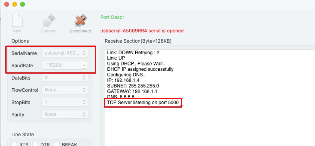
Testing the TCP Echo Server
After the project is flashed, the logs will print on the serial console. The image below shows the logs printed after initialization.
With the server active, it’s time to test it using any TCP client tool such as:
- Hercules Setup Utility,
- SocketTest,
- Tera Term (TCP mode), or
- RealTerm.
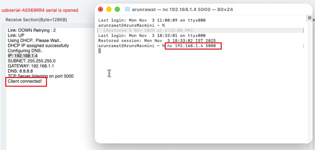
Enter the IP address of your STM32 board (the one printed in the serial logs) and connect to port 5000. Once you click Connect, you should see a message in the serial terminal confirming that a client has successfully connected.
The image below shows the “client connected” log on the console.
Now type any text in the client window and press Send. Immediately, the same text will appear on both:
- The serial monitor, showing what the STM32 received, and
- The client terminal, as the echoed response from the server.
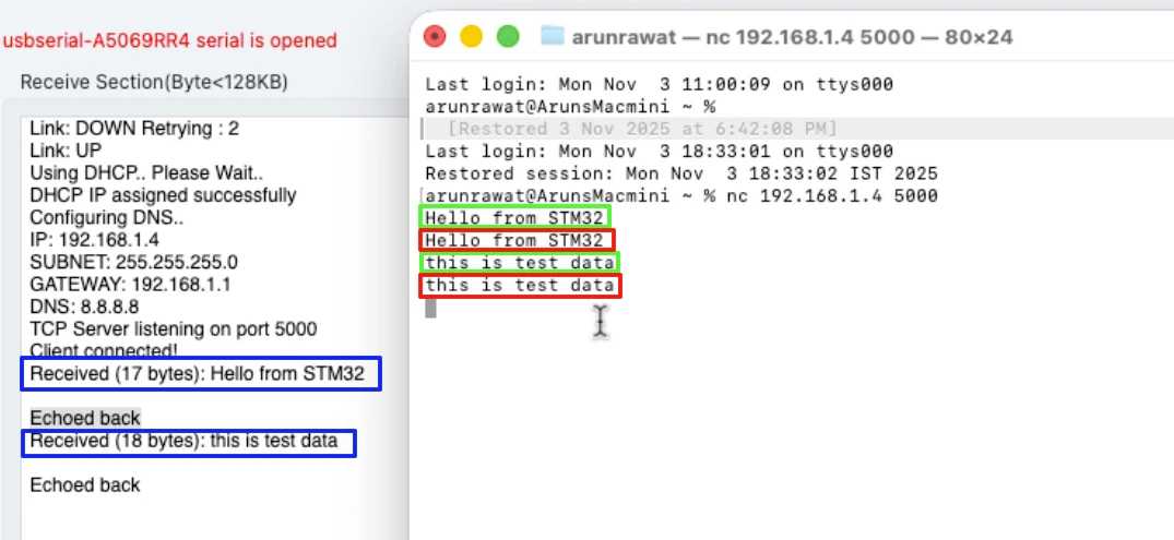
This confirms that the TCP echo server is working perfectly. The data sent by the client is received by the STM32 and sent back exactly as it is.
When the client disconnects, you’ll see corresponding messages in the console indicating that the connection was closed. The socket will then automatically reopen, allowing the server to accept a new client connection without restarting the microcontroller.
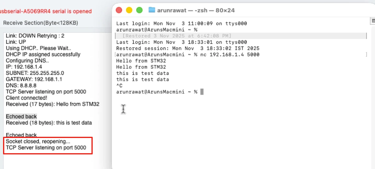
This continuous operation makes your STM32 W5500 TCP server stable and reliable, ready for real-world Ethernet communication.
Controlling STM32 LED via TCP
Now that our TCP echo server is working perfectly, let’s make it more useful by controlling an LED through Ethernet commands. This is a simple yet powerful example of how you can use data received from a TCP client to perform real actions on the STM32 microcontroller.
Configuring the LED Pin in CubeMX
First, open your project in STM32CubeMX. We’ll configure the onboard LED pin as a digital output.
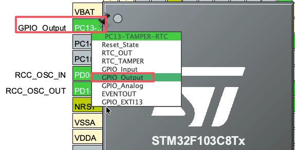
On the Bluepill (STM32F103) board, the onboard LED is connected to PC13. Configure it in the output mode.
The LED on the Bluepill is active low, which means:
- Setting the pin LOW (RESET) will turn the LED ON, and
- Setting it HIGH (SET) will turn the LED OFF.
We want the LED to stay OFF when the system starts, so set the initial output state to HIGH under the GPIO configuration tab.

After making these changes, generate the project code again so the new pin configuration is applied.
Writing LED Control Code in tcp_server.c
Now, let’s modify the tcp_server.c file to control the LED based on the data received from the client. Scroll down to the section where we previously used the send() function to echo back the received data. We’ll replace that part with our LED control logic.
Here’s what the code will do:
- Receive a string command from the client.
- Compare the received string with
"ON"or"OFF". - Update the LED state accordingly.
- Send a confirmation message back to the client.
Code snippet:
if (strcmp((char *)rx_buf, "ON") == 0)
{
    ledState = 0;  // Active LOW - LED ON
}
else if (strcmp((char *)rx_buf, "OFF") == 0)
{
    ledState = 1;  // LED OFF
}

// Control LED
led_Control(ledState);

// Prepare response message
sprintf((char *)tx_buf, "LED is %s\r\n", (ledState == 0) ? "ON" : "OFF");

// Send response back to client
send(SOCKET_NUMBER, tx_buf, strlen((char *)tx_buf));This simple logic allows the STM32 to respond to Ethernet commands instantly. Now we just need to define the led_Control() function that actually sets or resets the LED pin.
Implementing led_Control() in main.c
We declared the led_Control() function as extern in the tcp_server.c file, so now we’ll define it in main.c.
Add this function anywhere below your main code:
void led_Control (int value)
{
	HAL_GPIO_WritePin(GPIOC, GPIO_PIN_13, value);
}This function directly controls the LED pin based on the value of the value variable.
When the client sends "ON", the LED turns ON, and when it sends "OFF", the LED turns OFF.
Testing LED Control Commands
After the board starts:
- The serial console will display that the TCP server is listening on port 5000.
- Open your TCP client tool and Connect to the STM32’s IP address and port 5000.
Now try sending the following commands:
- Type OFF and press Send → The LED should turn OFF instantly.
- Type ON and press Send → The LED should turn ON immediately.
This is shown in the video below.
You can see the LED is responding to the commands sent by the client. Also note the confirmation messages in the client window:
LED is ON
LED is OFFIf you send any other message (for example, “HELLO”), nothing will happen. Only the valid commands (ON and OFF) trigger the LED action.
This simple test confirms that your STM32 W5500 TCP server is now capable of hardware control over Ethernet. It’s a great foundation for building advanced IoT applications, automation systems, or network-based device control.
Limitations of Blocking Mode
Our TCP server implementation works perfectly for receiving and responding to data. However, it currently uses blocking mode, which comes with some important limitations.
Understanding these limitations is crucial before moving on to more advanced multitasking setups using FreeRTOS.
Why recv() Blocks the CPU
In the current setup, we use the recv() function to receive data from the client:
len = recv(SOCKET_NUMBER, rx_buf, sizeof(rx_buf));The recv() function in this example works in blocking mode, meaning it waits indefinitely until the client sends some data. While it’s waiting, the CPU is completely occupied — it cannot perform any other task during this time.
This behavior is fine for simple projects or testing the TCP communication, but it becomes a major limitation in real applications.
For example:
- You cannot toggle other outputs or read sensors while waiting for data.
- Any periodic tasks like blinking a status LED or reading ADC values will pause.
- The system feels “frozen” until new data arrives from the client.
In embedded systems, efficient CPU usage is very important. The blocking mode wastes valuable processing time by keeping the MCU idle until new data is received.
This is where FreeRTOS comes in. It allows your project to handle multiple tasks at the same time, even while waiting for network data.
Next Step – Integrating FreeRTOS
To overcome the blocking issue, we’ll integrate FreeRTOS in the next part of this STM32 Ethernet tutorial series.
With FreeRTOS, we can:
- Run the TCP server as a separate task,
- Create other tasks for blinking LEDs, reading sensors, or handling user inputs, and
- Use task notifications or queues to communicate between tasks efficiently.
Even if the TCP server task is blocked waiting for data, other tasks will continue to run in the background — keeping the system responsive and efficient.
In the next tutorial, we’ll take the exact same project and extend it to work under FreeRTOS. You’ll learn how to manage blocking and non-blocking data reception, use task scheduling, and design a more flexible Ethernet-based STM32 system.
Video Tutorial
We’ll use the same hardware connections from the previous tutorial, so if you haven’t read that one yet, it’s best to go through it first before continuing.
STM32 W5500 TCP Server Video Tutorial
This video continues from Part 1 of the STM32 W5500 Ethernet series and demonstrates how to build a simple TCP echo server. It shows how to configure sockets, receive and send data, and even control an LED using TCP commands — all explained step-by-step in STM32CubeIDE.
Watch the TCP Server TutorialConclusion
In this part of the STM32 W5500 Ethernet tutorial series, we successfully created a TCP server that can both echo received data and use Ethernet commands to control hardware like an LED. This project demonstrated how the W5500 module handles TCP communication through simple functions such as socket(), listen(), recv(), and send(). We also saw how to check socket status and manage client connections efficiently.
By extending the echo server into an LED control interface, we learned how to turn received Ethernet data into real actions on the microcontroller. This example can easily be expanded to control relays, motors, or any other peripherals, making it a strong starting point for building IoT and network-based embedded systems.
However, since the current implementation uses blocking mode, it keeps the CPU waiting when no data is received. In the next part of this series, we’ll integrate FreeRTOS to solve this limitation — allowing multiple tasks to run simultaneously while maintaining stable Ethernet communication. This will make the system more flexible, responsive, and suitable for real-world applications.
Browse More STM32 W5500 Tutorials
STM32 W5500 Ethernet Tutorial (PART 3): TCP Server with FreeRTOS
STM32 W5500 Ethernet Tutorial (Part 4): Connect STM32 to TCP Server Using DNS and Static IP
STM32 W5500 Ethernet Tutorial (Part 5): HTTP Webserver on STM32
STM32 W5500 Ethernet Tutorial (Part 6): Dynamic HTTP Webserver using CGI
STM32 W5500 Ethernet Tutorial (Part 7): STM32 as MQTT Client
STM32 W5500 TCP Server Project Download
STM32 W5500 TCP Server FAQs
Subscribe
Login
0 Comments
Newest
