
Published: December 31, 2025
Last Updated: March 25, 2026
Last Updated: March 25, 2026
STM32 UART Receive Using Interrupt Mode with LL Drivers
UART communication is one of the most common features used in STM32 microcontrollers. In the previous tutorial, we received UART data using blocking mode with LL drivers. Blocking mode is simple. But it keeps the CPU busy while waiting for data.
In this tutorial, we will receive UART data using interrupt mode with STM32 LL drivers. This method is efficient and suitable for real applications.
We will first read raw data from UART and store it in a circular buffer. Then we will process simple commands to turn an LED ON or OFF.
How UART Receive Interrupt Works in STM32
Before writing any code, it is important to understand how the UART receive interrupt works internally in STM32.
When data arrives on the RX pin, the UART peripheral handles it in hardware. The CPU is involved only when needed. This is what makes interrupt mode efficient.
Let us break this process into simple steps.
RXNE Flag and RXNE Interrupt
RXNE stands for Receive Data Register Not Empty.
When a byte is received:
- UART shifts the data into the receive register
- RXNE flag becomes SET
- UART generates an interrupt request (if enabled)
This flag tells the microcontroller that new data is ready to be read. In LL drivers, we check this flag using:
LL_USART_IsActiveFlag_RXNE(USART2)Once RXNE is set, the CPU jumps to the USART interrupt handler. Inside the interrupt handler, we must read the data immediately.
uint8_t data = LL_USART_ReceiveData8(USART2);Reading the data does two things:
- Returns the received byte
- Automatically clears the RXNE flag
This is very important.
If RXNE is not cleared, the interrupt will fire again and again. That can lock your system. That is why data must always be read inside the ISR.
How RXNE Interrupt Is Enabled
RXNE interrupt is disabled by default. We must enable it manually using LL drivers.
LL_USART_EnableIT_RXNE(USART2);This allows UART to notify the CPU whenever new data arrives. Without this line, RXNE flag will still be set, but no interrupt will occur.
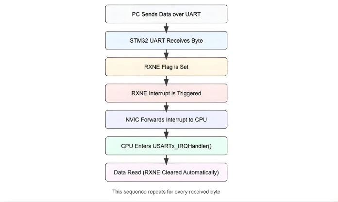
Visual Representation of UART Receive Interrupt Flow
The image below shows how a single byte travels from the PC to the STM32 CPU using the UART RX interrupt mechanism. This same flow repeats for every received byte.
UART Interrupt Setup in STM32CubeMX (LL Drivers)
We have already covered the basic UART configuration in the PART1 of this uart series, therefore, here we will just focus on the interrupt section.
Enabling USART2 Interrupt for Nucleo-F446
Nucleo boards come with an onboard ST-Link debugger that also provides a Virtual COM Port (VCP). This VCP is connected internally to USART2, making it a great choice for UART communication without additional hardware.
The image below shows the USART2 configuration in the CubeMX.
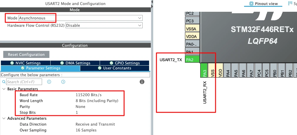
To enable USART2 in CubeMX:
- Open Connectivity -> USART2.
- Set the Mode to Asynchronous.
- CubeMX automatically assigns the correct pins:
- PA2 -> TX
- PA3 -> RX
- Keep the Baud Rate to a common value like 115200.
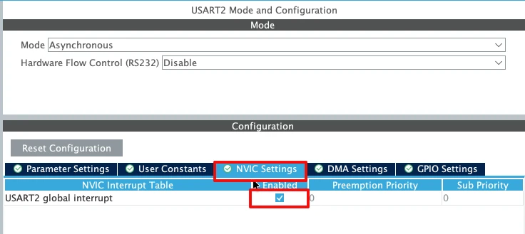
Now enable the USART2 interrupt in the NVIC tab as shown in the image below.
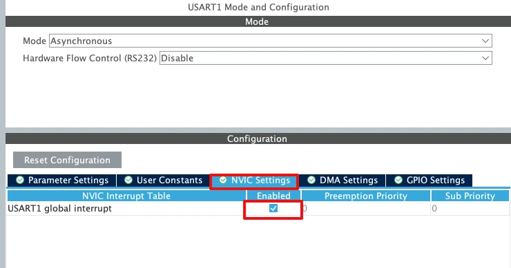
Enabling USART1 Interrupt for STM32F103C8
For the STM32F103C8 (Blue Pill), USART1 is the most commonly used UART port because the pins are easy to access. The image below shows the USART1 configuration in the CubeMX.
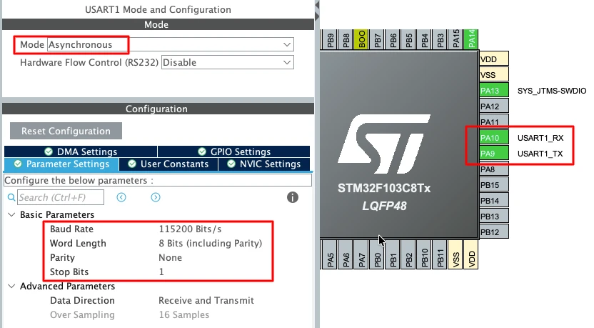
To enable USART1 in CubeMX:
- Open Connectivity -> USART1.
- Set the Mode to Asynchronous.
- The default pin mapping is:
- PA9 -> TX
- PA10 -> RX
- Use a standard 115200 baud rate for smooth communication.
Enable the USART1 interrupt in the NVIC tab as shown in the image below.
Important UART Configuration Parameters
When setting up UART for basic transmit, a few key parameters must be selected correctly:
- Baud Rate
Defines how fast the data is sent.
Common values: 9600, 57600, 115200.
For logs and debugging, 115200 works best. - Word Length
Use 8 Bits for normal communication. - Stop Bits
Set this to 1 Stop Bit. - Parity
Keep it None unless required by a special protocol. - Hardware Flow Control
Disable it. (None)
STM32 UART Interrupt Configuration Using LL Drivers
Now that we understand how the UART receive interrupt works, it is time to configure it using STM32 LL drivers. In this section, we will enable the UART receive interrupt, and create the required buffers.
Enabling UART RX Interrupt
By default, the UART receive interrupt is disabled. Even if the UART receives data, no interrupt will occur unless RXNE interrupt is enabled. In LL drivers, this is done using a single function.
LL_USART_EnableIT_RXNE(USART2);This line allows the UART peripheral to generate an interrupt whenever a new byte is received.
Without this step:
- RXNE flag will still be set
- Data will be received
- Interrupt handler will never execute
So this line is mandatory for interrupt-based reception.
Creating Receive Buffer and Flags
We need a place to store received data. We also need a way to inform the main loop when a full message is received. For this, we create a buffer and a few flags.
#define RX_BUF_SIZE 20

uint8_t rxBuf[RX_BUF_SIZE];
volatile uint32_t rxIndex = 0;
volatile uint8_t rxComplete = 0;Here is how these variables are used:
rxBufstores the received bytesrxIndextracks the current buffer positionrxCompletesignals that a full message is ready
The volatile keyword is important. These variables are modified inside an interrupt. Without volatile, the compiler may optimize them incorrectly.
Receiving UART Data Simply Using USART Interrupt Handler (Circular Buffer Method)
In this section, we will write the USART interrupt handler and receive data in the simplest possible way. We will store received bytes in a circular buffer. This method is efficient and works well for continuous data streams.
No command parsing is done here. We only focus on safe and continuous reception.
Receiving Data Inside USART Interrupt Handler
When UART receives a byte, the RXNE interrupt is triggered. Inside the interrupt handler, we must read the data immediately.
if (LL_USART_IsActiveFlag_RXNE(USART2))
{
rxBuf[rxIndex++] = LL_USART_ReceiveData8(USART2);
}Here is what happens:
- RXNE flag confirms new data
- Data is read from UART
- Byte is stored in the receive buffer
Reading the data automatically clears the RXNE flag.
Implementing Circular Buffer Logic
To avoid buffer overflow, we use a circular buffer. When the buffer reaches the end, the index resets to zero.
if (rxIndex >= RX_BUF_SIZE)
rxIndex = 0;This allows the buffer to be reused continuously. The buffer never stops receiving data. Older data is overwritten by newer data.
This approach is ideal for:
- Continuous UART streams
- Sensor data
- Debug logs
- Serial monitoring
Complete USART RX Handler Function
We now combine everything into a single receive function.
void USART2_IRQ_Handler(void)
{
// RXNE interrupt
if (LL_USART_IsActiveFlag_RXNE(USART2))
{
rxBuf[rxIndex++] = LL_USART_ReceiveData8(USART2);
if (rxIndex >= RX_BUF_SIZE)
rxIndex = 0;
}
}This function:
- Handles UART receive interrupt
- Stores data in a circular buffer
- Prevents buffer overflow
- Keeps ISR short and fast
Calling User Handler from STM32 Interrupt File
The USART2 interrupt handler must be defined in the interrupt file.
This file is usually named:
stm32f4xx_it.c- or
stm32xx_it.c(depending on MCU)
The user-defined function must be declared as extern and then called inside the actual IRQ handler.
extern void USART2_IRQ_Handler(void);
void USART2_IRQHandler(void)
{
USART2_IRQ_Handler();
}Output showing simple reception
The image below shows the data sent by the PC is received by the STM32. The data is stored in the buffer (rxBuf).
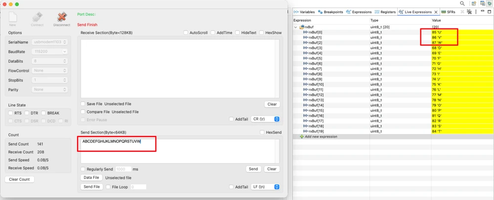
Also note that the first 3 bytes of the rxBuf has been overwritten by the new data. The circular buffer method overrides the old data when the new data arrives. Therefore we must process the data before it gets overwritten.
This is explained in the next section.
Processing UART Data Properly Using USART Interrupt Handler and Command Parsing
In this section, we detect the end of a command using a predefined character, store the complete message safely inside a buffer, and then process the received command inside the main loop instead of the interrupt. Based on the received data, we finally control a GPIO pin, such as turning an LED ON or OFF. This approach keeps the interrupt handler short, avoids blocking code, and ensures reliable UART communication.
Detecting End of Command Inside Interrupt Handler
We use a special character to detect the end of a command. In this example, the newline character (\n) marks the end of data.
uint8_t data = LL_USART_ReceiveData8(USART2);Each received byte is checked immediately.
if (data == '\n')
{
rxBuf[rxIndex] = '\0';
rxIndex = 0;
rxComplete = 1;
}Here is what happens:
'\n'signals end of command- String is null-terminated
- Receive index is reset
- A flag notifies the main loop
This keeps the interrupt handler short and fast.
Storing Incoming Data Safely
If the received byte is not the end character, it is stored in the buffer.
rxBuf[rxIndex++] = data;To avoid buffer overflow, we reset the index when needed.
if (rxIndex >= RX_BUF_SIZE)
rxIndex = 0;This ensures stable operation even with invalid or long inputs.
Complete USART Interrupt Handler with Command Detection
Below is the complete interrupt handler used for command reception.
void USART2_IRQ_Handler(void)
{
// RXNE interrupt
if (LL_USART_IsActiveFlag_RXNE(USART2))
{
uint8_t data = LL_USART_ReceiveData8(USART2);
if (data == '\n') // End of command
{
rxBuf[rxIndex] = '\0';
rxIndex = 0;
rxComplete = 1;
}
else
{
rxBuf[rxIndex++] = data;
if (rxIndex >= RX_BUF_SIZE)
rxIndex = 0;
}
}
}This handler:
- Receives UART data using interrupt
- Detects command completion
- Signals the main loop for processing by setting the
rxCompleteflag to 1.
Processing Commands Inside Main Loop
Interrupts should not perform heavy operations. String comparison and GPIO control must be done in the main loop.
if (rxComplete)
{
rxComplete = 0;
processCommand();
}This keeps the system responsive and safe.
Command Processing Function
The command processing logic is kept in a separate function.
void processCommand(void)
{
if (strcmp((char *)rxBuf, "ON") == 0)
{
LL_GPIO_SetOutputPin(GPIOA, LL_GPIO_PIN_5);
}
else if (strcmp((char *)rxBuf, "OFF") == 0)
{
LL_GPIO_ResetOutputPin(GPIOA, LL_GPIO_PIN_5);
}
}Here is how it works:
"ON"turns the LED ON"OFF"turns the LED OFF- Commands are case-sensitive
This structure makes the code easy to expand.
Complete STM32 UART Receive Using Interrupt Mode with LL Drivers (Full Working Code)
Below is the complete working code, written using STM32 LL drivers, that demonstrates how to receive UART data using interrupt mode, process commands safely in the main loop, and control a GPIO pin (LED) based on received commands.
- This example receives strings like
ONandOFFfrom a serial terminal. - The UART interrupt collects data until a newline character (
\n) is received. - The command is then processed outside the interrupt to keep the system stable and responsive.
#include "main.h"
#include <string.h>
/* USER CODE BEGIN 0 */
#define RX_BUF_SIZE 20

uint8_t rxBuf[RX_BUF_SIZE];
volatile uint32_t rxIndex = 0;
volatile uint8_t rxComplete = 0;
/* Process received command */
void processCommand(void)
{
if (strcmp((char *)rxBuf, "ON") == 0)
{
LL_GPIO_SetOutputPin(GPIOA, LL_GPIO_PIN_5);
}
else if (strcmp((char *)rxBuf, "OFF") == 0)
{
LL_GPIO_ResetOutputPin(GPIOA, LL_GPIO_PIN_5);
}
}
/* User-defined USART RX handler */
void USART2_IRQ_Handler(void)
{
// RXNE interrupt
if (LL_USART_IsActiveFlag_RXNE(USART2))
{
uint8_t data = LL_USART_ReceiveData8(USART2);
if (data == '\n') // End of command
{
rxBuf[rxIndex] = '\0';
rxIndex = 0;
rxComplete = 1;
}
else
{
rxBuf[rxIndex++] = data;
if (rxIndex >= RX_BUF_SIZE)
    rxIndex = 0;
}
}
}
/* USER CODE END 0 */
int main(void)
{
/* MCU Configuration */
LL_APB2_GRP1_EnableClock(LL_APB2_GRP1_PERIPH_SYSCFG);
LL_APB1_GRP1_EnableClock(LL_APB1_GRP1_PERIPH_PWR);
NVIC_SetPriorityGrouping(NVIC_PRIORITYGROUP_4);
NVIC_SetPriority(SysTick_IRQn, NVIC_EncodePriority(NVIC_GetPriorityGrouping(), 15, 0));
/* Configure the system clock */
SystemClock_Config();
/* Initialize peripherals */
MX_GPIO_Init();
MX_USART2_UART_Init();
/* USER CODE BEGIN 2 */
// Enable UART RX interrupt
LL_USART_EnableIT_RXNE(USART2);
/* USER CODE END 2 */
/* Infinite loop */
while (1)
{
if (rxComplete)
{
rxComplete = 0;
processCommand();
}
}
}
/* Interrupt file (stm32xx_it.c) */
extern void USART2_IRQ_Handler(void);

void USART2_IRQHandler(void)
{
    USART2_IRQ_Handler();
}
This single code listing shows the entire UART interrupt receive flow using LL drivers, from data reception to command processing and GPIO control.
Output: LED Control via UART
The video below shows the UART communication and LED behavior when the program is running on the STM32 board.
In the serial terminal, text commands are sent to the microcontroller through UART. Each command is typed as plain text and followed by the Enter key.
When the ON command is sent, the STM32 receives the characters, processes the command, and turns the LED ON. When the OFF command is sent, the LED turns OFF.
If an invalid command such as ONE is sent, the command is ignored. The LED state does not change, which confirms that only valid commands are processed.
Conclusion
In this tutorial, we learned how to receive UART data on an STM32 using interrupt mode with LL drivers. We started by understanding the RXNE flag and how the NVIC allows the CPU to respond to UART interrupts. Then, we configured the UART and NVIC, created a receive buffer, and wrote a USART interrupt handler to store incoming data in a circular buffer. Finally, we processed the commands safely in the main loop to control a GPIO pin based on received input.
This approach is highly useful for real-time embedded systems because it allows the CPU to perform other tasks while UART data is being received. By handling only the reception inside the interrupt and processing commands outside, the system remains responsive, stable, and efficient. It also provides a foundation for building more complex UART-based communication, such as command parsing, debugging interfaces, or controlling peripherals via serial commands.
In the next tutorial, we will take this further by learning how to receive UART data using DMA (Direct Memory Access). This method allows even higher efficiency, letting the CPU completely ignore incoming UART data until a full buffer is ready, which is perfect for continuous high-speed data streams or larger datasets.
Browse More STM32 LL Tutorials
STM32 LL GPIO Input and EXTI Interrupt Tutorial: Read Buttons With Low-Level Drivers
STM32 UART using LL Drivers (Part 1): Transmit using Polling Mode
STM32 UART using LL Drivers (Part 2): Transmit using Interrupt & DMA
STM32 UART using LL Drivers (Part 3): Receive Data in Blocking Mode
STM32 UART using LL Drivers (Part 5): Receive Using DMA (Normal and Circular Mode)
STM32 ADC Using LL Drivers (Part 1): Single Channel Blocking and Interrupt Mode
STM32 ADC Using LL Drivers (Part 2): Multiple Channels using DMA Mode
STM32 LL UART Project Download
STM32 LL UART Receive FAQs
Subscribe
Login
0 Comments
Newest
