
Published: December 24, 2025
Last Updated: March 25, 2026
Last Updated: March 25, 2026
STM32 UART Receive Data in Blocking Mode using LL Drivers
UART reception is just as important as transmission. In many applications, the microcontroller must receive commands, data packets, or user input through the serial port.
In this 3rd part of the STM32 UART LL Drivers series, we will learn how to receive data in blocking mode using LL drivers. This method is simple. It is easy to understand. It is also a good starting point before moving to interrupt or DMA-based reception.
We will first read raw data from UART. Then we will process simple commands to turn an LED ON or OFF.
Introduction to UART Receive in Blocking Mode
Receiving data through UART is a common requirement in embedded systems. The microcontroller often needs to read commands, configuration data, or user input from a serial terminal.
In this section, we focus on UART receive in blocking mode using STM32 LL drivers. This is the simplest way to read data from UART. It helps you understand how UART reception works at the register and flag level before moving to advanced methods.
Blocking mode relies on continuously checking the UART receive flag and reading data when it becomes available.
What Is Blocking Mode in UART Reception
In blocking mode, the CPU waits for data to arrive on the UART peripheral. The code keeps checking the RXNE (Receive Data Register Not Empty) flag.
When RXNE becomes set:
- A byte has arrived on the UART line
- The CPU reads the data register
- Code execution continues
Until RXNE is set, the CPU stays inside the checking loop. This is why it is called blocking UART receive.
When Blocking UART Receive Is Useful
Blocking UART receive is useful in many simple scenarios.
It works well when:
- The application is small
- Only one task is running
- UART data rate is low
- Timing is not critical
- You are learning STM32 UART basics
It is also useful for quick testing and debugging using a serial terminal. Because the code is easy to write and easy to understand, blocking mode is often the first step in UART learning.
Limitations of Blocking Mode
Blocking mode has important limitations. The main issues are:
- CPU stays busy while waiting for data
- Other tasks cannot run efficiently
- Power consumption increases
- Not suitable for real-time or multitasking systems
As the project grows, blocking UART receive becomes a bottleneck. That is why professional applications use interrupt-based or DMA-based UART reception.
In the next parts of this series, we will solve these limitations step by step.
UART Setup in STM32CubeMX (LL Drivers)
STM32CubeMX makes the initial setup simple by generating the basic project structure for us. Since CubeMX handles the boilerplate code, the focus here is only on the UART configuration needed for receiving data using LL drivers. Once UART is enabled and configured, we can directly start writing code in the main file.
STM32 Clock Configuration
Before generating the project, we must configure the system clock. Open the Clock Configuration tab in CubeMX.
For the STM32F446RE, we will use the 8 MHz external crystal in bypass mode. This is the default clock source on the Nucleo board. The bypass mode uses the clock from the on-board ST-Link MCU.
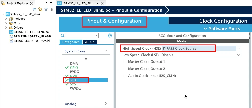
We will feed this into the PLL and run the system at 180 MHz, which is the maximum frequency for this MCU.
The image below shows the complete PLL and clock configuration used to achieve 180 MHz.
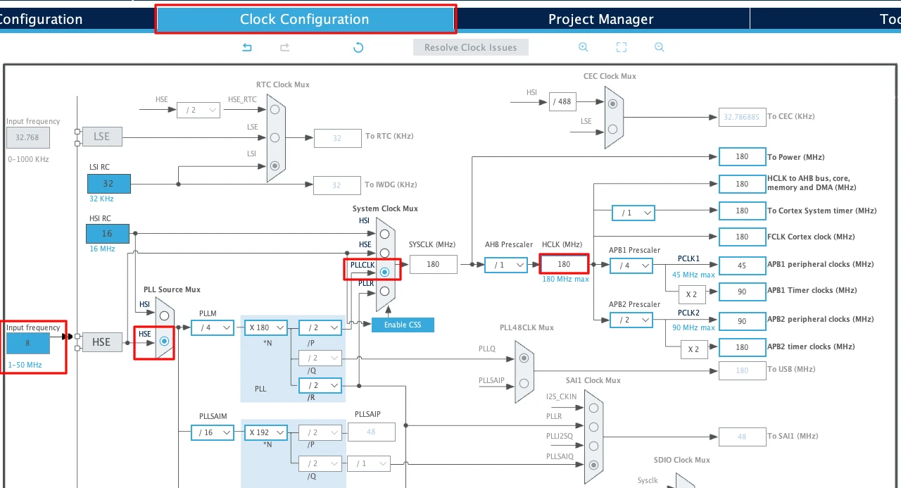
This fast system clock ensures accurate delays and smooth blinking using LL drivers. The SysTick timer will also run from this 180 MHz system clock, which becomes important in the delay functions we will use later.
Note for STM32F103C8:
This MCU uses an 8 MHz external crystal as well, but its maximum frequency is 72 MHz. If you are using the Blue Pill, configure the PLL so that the final system clock is 72 MHz.
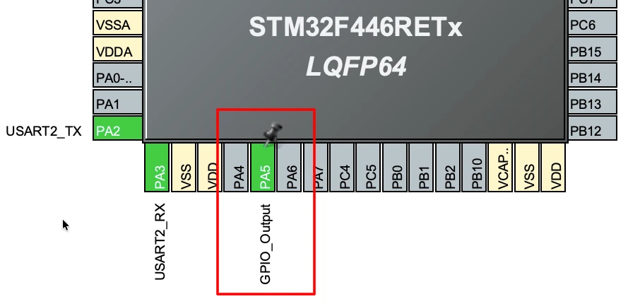
Enabling USART2 for Nucleo-F446
Nucleo boards come with an onboard ST-Link debugger that also provides a Virtual COM Port (VCP). This VCP is connected internally to USART2, making it a great choice for UART communication without additional hardware.
The image below shows the USART2 configuration in the CubeMX.
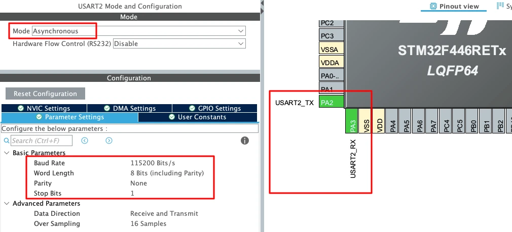
To enable USART2 in CubeMX:
- Open Connectivity -> USART2.
- Set the Mode to Asynchronous.
- CubeMX automatically assigns the correct pins:
- PA2 -> TX
- PA3 -> RX
- Keep the Baud Rate to a common value like 115200.
Enabling USART1 for STM32F103C8
For the STM32F103C8 (Blue Pill), USART1 is the most commonly used UART port because the pins are easy to access. The image below shows the USART1 configuration in the CubeMX.
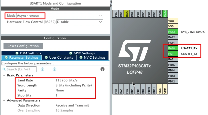
To enable USART1 in CubeMX:
- Open Connectivity -> USART1.
- Set the Mode to Asynchronous.
- The default pin mapping is:
- PA9 -> TX
- PA10 -> RX
- Use a standard 115200 baud rate for smooth communication.
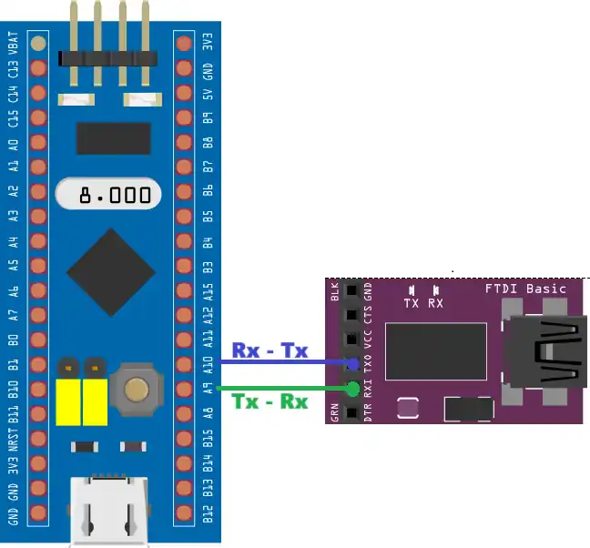
This UART will connect to a USB-TTL converter, which links the board to your PC. The connection is simple, connecting the pin PA9 -> RX of the module and PA10 -> TX of the module.
Important UART Configuration Parameters
When setting up UART for basic transmit, a few key parameters must be selected correctly:
- Baud Rate
Defines how fast the data is sent.
Common values: 9600, 57600, 115200.
For logs and debugging, 115200 works best. - Word Length
Use 8 Bits for normal communication. - Stop Bits
Set this to 1 Stop Bit. - Parity
Keep it None unless required by a special protocol. - Hardware Flow Control
Disable it. (None)
These settings ensure compatibility with most serial terminals and USB-TTL adapters, keeping the communication stable and predictable.
Configure LED GPIO Pin
We will configure the Pin PA5 as the GPIO Output. The LED will be later controlled by receiving the command from the computer using UART.
Understanding UART RX Flags in LL Drivers
UART reception in STM32 is controlled using status flags. When you work with LL drivers, you interact directly with these flags instead of using callbacks.
For blocking mode UART receive, everything depends on a single flag: RXNE.
Let us understand this flag by writing small and clear functions.
RXNE Flag Explained
RXNE means Receive Data Register Not Empty. When a byte is received on the UART RX pin, the hardware places it in the data register and sets the RXNE flag.
The CPU must:
- Check the RXNE flag
- Read the data register
- Allow the hardware to clear RXNE automatically
The following function checks whether RX data is available.
int isDataAvailable(void)
{
    return LL_USART_IsActiveFlag_RXNE(USART2);
}Here is what happens step by step:
LL_USART_IsActiveFlag_RXNE()reads the USART status register- It checks whether RXNE is set
- If a byte has arrived, it returns 1
- If no data is present, it returns 0
This function is the foundation of blocking UART receive.
How LL_USART_IsActiveFlag_RXNE Works
Once RXNE is set, the next step is to read the received byte. This is done by reading the UART data register. The LL driver provides a simple function for this.
int uartReadByte(void)
{
return LL_USART_ReceiveData8(USART2);
}This function performs a direct register read.
- It reads one byte from the USART receive data register
- The RXNE flag is cleared automatically by the hardware
- The returned value is the received character
These two functions always work together:
- First, check if data is available
- Then, read the byte safely
A typical blocking receive flow looks like this:
if (isDataAvailable())
{
char ch = uartReadByte();
}This approach keeps the code simple, readable, and close to the hardware. It is also the exact logic used in many professional STM32 applications before moving to interrupt-based reception.
Simple UART Receive Code in Blocking Mode
Now that we understand the RXNE flag and how LL drivers work, we can write a complete UART receive logic in blocking mode. In this section, we will build the code step by step using small functions.
Buffer and Index Definition
First, we define a buffer to store received data. We also need an index to keep track of the current position in the buffer.
#define BUF_SIZE 20
int indx = 0;
uint8_t buffer[BUF_SIZE];bufferstores the received UART bytesindxpoints to the next free positionBUF_SIZElimits how much data we can store
This simple structure is enough for basic UART reception.
Checking If Data Is Available
Before reading any data, we must check whether a byte has arrived. This is done by checking the RXNE flag.
int isDataAvailable(void)
{
    return LL_USART_IsActiveFlag_RXNE(USART2);
}- This function checks the RXNE flag
- It returns 1 if data is available
- It returns 0 if no data is present
Reading a Single Byte from UART
Once data is available, we read it from the UART data register.
int uartReadByte(void)
{
    return LL_USART_ReceiveData8(USART2);
}- This function reads one byte from USART2
- RXNE is cleared automatically after the read
- The received byte is returned to the caller
Receiving Data Inside the Main Loop
Now we combine everything inside the main loop.
while (1)
{
if (isDataAvailable())
{
buffer[indx++] = uartReadByte();
if (indx == BUF_SIZE)
indx = 0;
}
}Here is what this code does:
- The CPU keeps checking for incoming data
- When data arrives, one byte is read
- The byte is stored in the buffer
- The index is incremented
- If the buffer is full, the index resets
This is a pure blocking UART receive implementation.
Complete Working Code Example
Below is the full example that combines all parts together. This code continuously receives UART data and stores it in a buffer.
#define BUF_SIZE 20
int indx = 0;
uint8_t buffer[BUF_SIZE];
int isDataAvailable(void)
{
return LL_USART_IsActiveFlag_RXNE(USART2);
}
int uartReadByte(void)
{
    return LL_USART_ReceiveData8(USART2);
}
int main(void)
{
SystemClock_Config();
MX_GPIO_Init();
MX_USART2_UART_Init();
while (1)
{
if (isDataAvailable())
{
buffer[indx++] = uartReadByte();
if (indx == BUF_SIZE)
indx = 0;
}
}
}This example is simple, easy to understand, and ideal for learning.
Output
The image below shows the data sent by the computer via serial terminal. The same data is received by the STM32, and it is stored in the buffer.
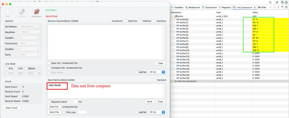
In the next section, we will extend this logic to process commands received over UART, such as turning an LED ON or OFF.
Processing UART Commands to Control an LED
Now that we can receive UART data in blocking mode, we can make it useful. In this section, we will process text-based commands received from a serial terminal.
We will send commands like ON or OFF from the PC. The STM32 will receive the command and controls an LED.
Command Format and Logic
We will use plain ASCII commands.
- Each command is a short text string
- Commands end with newline (
\n) or carriage return (\r) - The received characters are stored in a buffer
- When a line ends, the command is processed
This makes the UART interface easy to use with any serial terminal.
Handling Newline and Carriage Return
Newline and carriage return characters indicate the end of a command.
if (ch == '\n' || ch == '\r')
{
buffer[indx] = '\0'; // terminate string
if (indx > 0)
{
processCommand();
}
indx = 0; // reset for next command
}Here is what happens:
- The received string is terminated with
\0 - Empty commands are ignored
- The buffer index is reset for the next command
This allows clean command parsing.
Preventing Buffer Overflow
We must always protect the buffer from overflow. This is important for safety and stability.
else
{
if (indx < (BUF_SIZE - 1))
{
buffer[indx++] = ch;
}
else
{
// buffer overflow → discard command safely
indx = 0;
}
}This logic ensures:
- The buffer never exceeds its size
- Invalid or long commands are discarded
- The system continues to run safely
Processing ON and OFF Commands
Once a command is received, we compare it with known strings.
void processCommand(void)
{
if (strcmp((char *)buffer, "ON") == 0)
{
LL_GPIO_SetOutputPin(GPIOA, LL_GPIO_PIN_5);
}
else if (strcmp((char *)buffer, "OFF") == 0)
{
LL_GPIO_ResetOutputPin(GPIOA, LL_GPIO_PIN_5);
}
}ONturns the LED ONOFFturns the LED OFF- Invalid commands are ignored
This function can be extended easily for more commands.
Complete Code Example with LED Control
Below is the complete working example. It receives UART commands in blocking mode and controls an LED.
#define BUF_SIZE   20

int indx = 0;
uint8_t buffer[BUF_SIZE];
int isDataAvailable(void)
{
    return LL_USART_IsActiveFlag_RXNE(USART2);
}
int uartReadByte(void)
{
    return LL_USART_ReceiveData8(USART2);
}
void processCommand(void)
{
    if (strcmp((char *)buffer, "ON") == 0)
    {
        LL_GPIO_SetOutputPin(GPIOA, LL_GPIO_PIN_5);
    }
    else if (strcmp((char *)buffer, "OFF") == 0)
    {
        LL_GPIO_ResetOutputPin(GPIOA, LL_GPIO_PIN_5);
    }
}
int main(void)
{
SystemClock_Config();
MX_GPIO_Init();
MX_USART2_UART_Init();
while (1)
{
if (isDataAvailable())
{
char ch = uartReadByte();
if (ch == '\n' || ch == '\r')
{
buffer[indx] = '\0';
if (indx > 0)
{
processCommand();
}
indx = 0;
}
else
{
if (indx < (BUF_SIZE - 1))
{
buffer[indx++] = ch;
}
else
{
indx = 0;
}
}
}
}
}This example shows how STM32 UART receive in blocking mode can be used to build real applications.
Output: LED Control via UART
The video below shows the UART communication and LED behavior when the program is running on the STM32 board.
In the serial terminal, text commands are sent to the microcontroller through UART. Each command is typed as plain text and followed by the Enter key.
When the ON command is sent, the STM32 receives the characters, processes the command, and turns the LED ON. When the OFF command is sent, the LED turns OFF.
If an invalid command such as ONE is sent, the command is ignored. The LED state does not change, which confirms that only valid commands are processed.
This output verifies that UART receive in blocking mode using STM32 LL drivers is working correctly and that command parsing is functioning as expected.
Conclusion
In this post, we learned how to receive UART data in blocking mode using STM32 LL drivers. We started by understanding the RXNE flag, then built simple functions to check data availability and read bytes from UART. After that, we implemented a complete blocking receive logic and used it to process text-based commands to control an LED. This helped us see how raw UART data can be converted into meaningful actions inside an embedded application.
Blocking UART receive is easy to understand and very useful for learning, testing, and small projects. However, it keeps the CPU busy while waiting for data. In the next part of this series, we will move to UART receive using interrupts, where the CPU no longer waits actively and data is handled more efficiently. This will make the system more responsive and suitable for real-world STM32 applications.
Browse More STM32 LL Tutorials
STM32 LL GPIO Input and EXTI Interrupt Tutorial: Read Buttons With Low-Level Drivers
STM32 UART using LL Drivers (Part 1): Transmit using Polling Mode
STM32 UART using LL Drivers (Part 2): Transmit using Interrupt & DMA
STM32 UART using LL Drivers (Part 4): Receive Data in Interrupt Mode
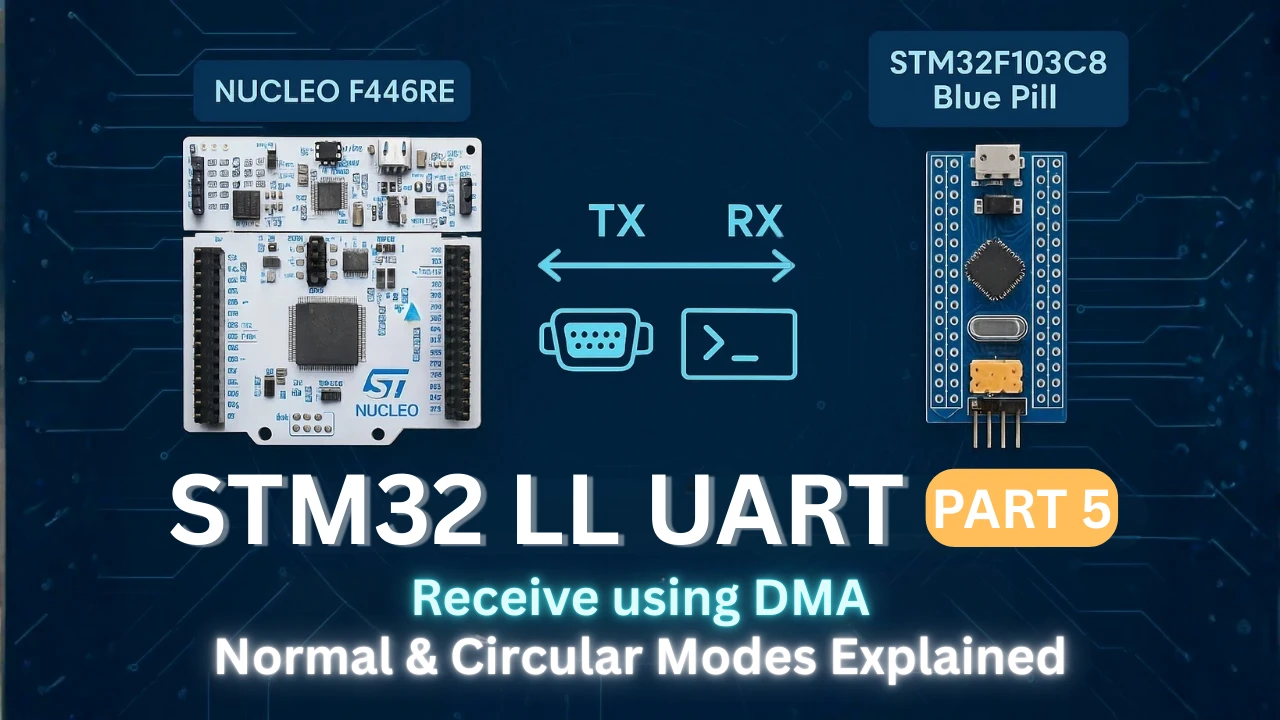
STM32 UART using LL Drivers (Part 5): Receive Using DMA (Normal and Circular Mode)
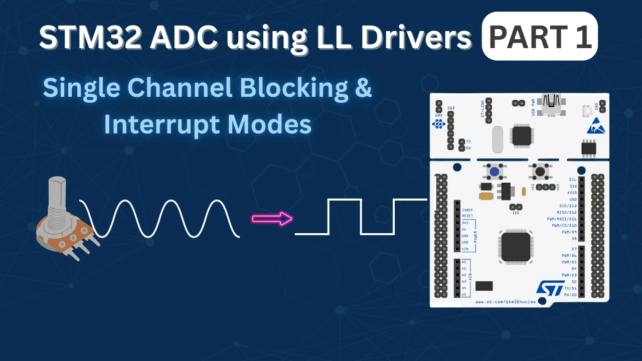
STM32 ADC Using LL Drivers (Part 1): Single Channel Blocking and Interrupt Mode
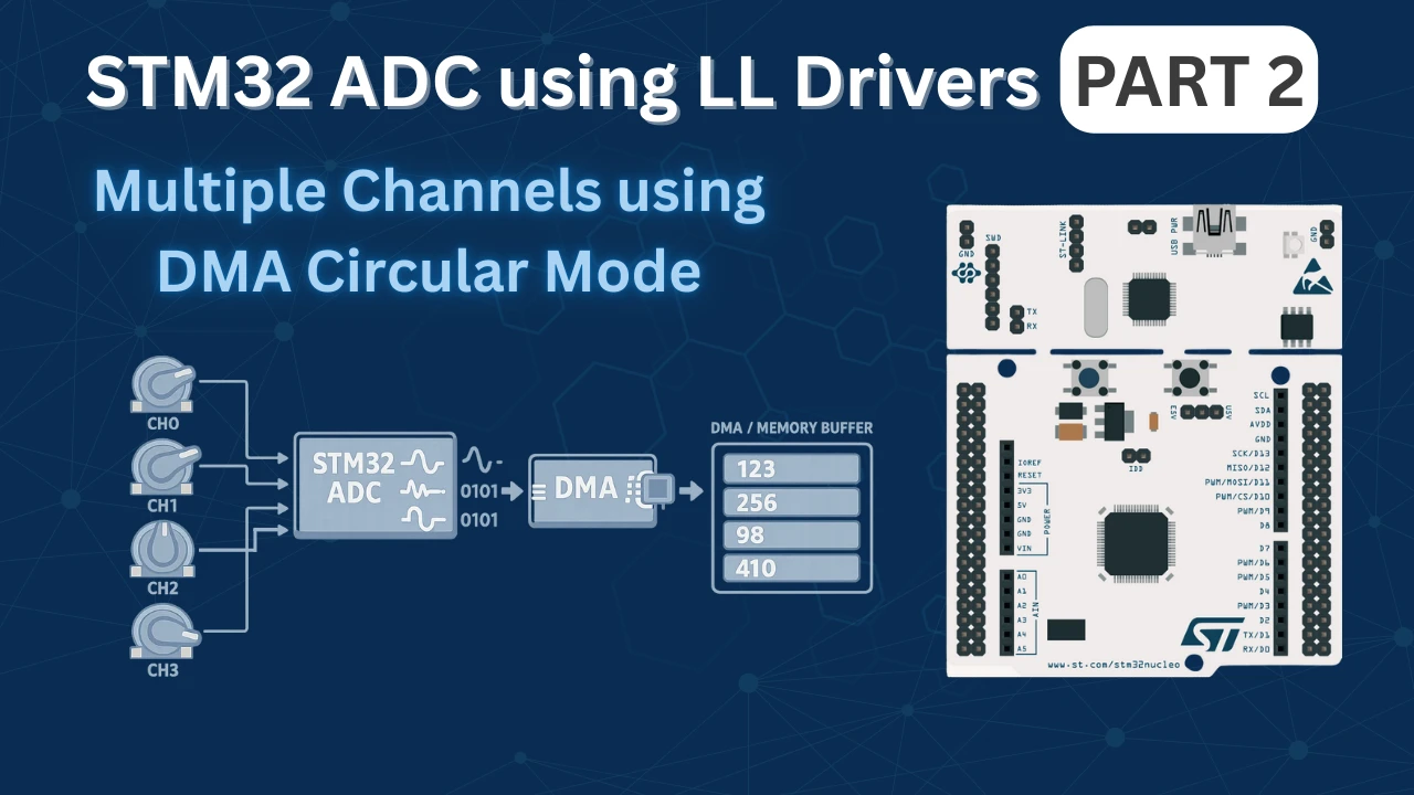
STM32 ADC Using LL Drivers (Part 2): Multiple Channels using DMA Mode
STM32 LL UART Project Download
STM32 LL UART Receive FAQs
Subscribe
Login
0 Comments
Newest
