
Published: December 9, 2025
Last Updated: March 25, 2026
Last Updated: March 25, 2026
STM32 UART Transmit Tutorial using LL Drivers (Polling Mode)
UART is one of the easiest ways to send data from an STM32 board to a PC. It helps in debugging, logging, and building communication with other devices. In this first part of the STM32 UART series, the focus stays on UART transmit in polling mode using the STM32 LL drivers.
The tutorial works on any STM32 board, and for demonstration it includes examples from both the Nucleo-F446RE and the STM32F103C8 Blue Pill. The Nucleo boards already come with a Virtual COM Port (VCP), so no additional hardware is required. Boards like the Blue Pill need a USB-TTL converter, and the connection steps are explained clearly.
This guide uses STM32CubeMX to generate the project, so there is no need to set up clocks or registers manually. The focus stays on writing simple and readable UART transmit code using LL functions, and also implementing printf output using the int _write() function.
By the end of this post, the board will send text messages to your PC through UART, and you will see them in any serial terminal. This creates the foundation for more advanced UART tutorials in the upcoming parts.
Introduction to UART Transmit in STM32 LL
UART is one of the most reliable and widely used communication interfaces in embedded systems. It helps send data between the microcontroller and a PC, sensor, or another device. In STM32, the Low-Layer (LL) drivers provide a fast and lightweight way to work with UART, making them an excellent choice when performance and control matter.
This part of the series focuses on sending data using UART in polling mode, keeping everything simple and easy to understand.
Why Start with Polling Mode?
Polling mode is the simplest way to transmit data over UART. The CPU checks the UART flags and sends each byte only when the hardware is ready. This approach removes the complexity of interrupts or DMA and helps beginners understand what happens at the hardware level.
It is ideal for learning because:
- The flow of the program is easy to follow.
- No interrupt handlers are required.
- Debugging becomes straightforward.
- It gives a clear idea of UART flags and timing.
Once polling mode is clear, switching to interrupt or DMA mode becomes much easier.
Boards Used: Nucleo-F446RE and STM32F103C8 Blue Pill
Although the tutorial applies to any STM32 board, two popular boards are used for demonstration:
Nucleo-F446RE:
Comes with an onboard Virtual COM Port (VCP) connected through USART2. This allows easy UART communication using only a regular USB cable.
STM32F103C8 Blue Pill:
This board does not include a built-in USB-UART bridge. A simple USB-TTL converter is needed to connect the MCU’s UART pins to the PC’s serial port.
Both boards are easy to set up and behave the same at the code level, which makes them perfect choices for learning UART transmit using LL drivers.
STM32 UART Hardware Connections
To send data from the STM32 to your PC, you must connect the UART pins correctly. The Nucleo board makes this very easy with its built-in Virtual COM Port, while boards like the STM32F103C8 require a USB-TTL converter. Once the TX and RX pins are wired correctly, any serial terminal on your PC can read the transmitted data.
UART Connection via Virtual COM Port (VCP)
Some of the Nucleo and Discovery dev boards from ST supports the virtual com port. This feature enables the USB connected for the ST-link to be also used for the data transmission between the MCU and the computer.
The Virtual Com Port is supported by many Nucleo and Discovery boards but not all. You need to check the schematic of the board to confirm whether the respective board supports it.
Below are the images from the schematic of the Nucleo F446RE and Discovery F412.
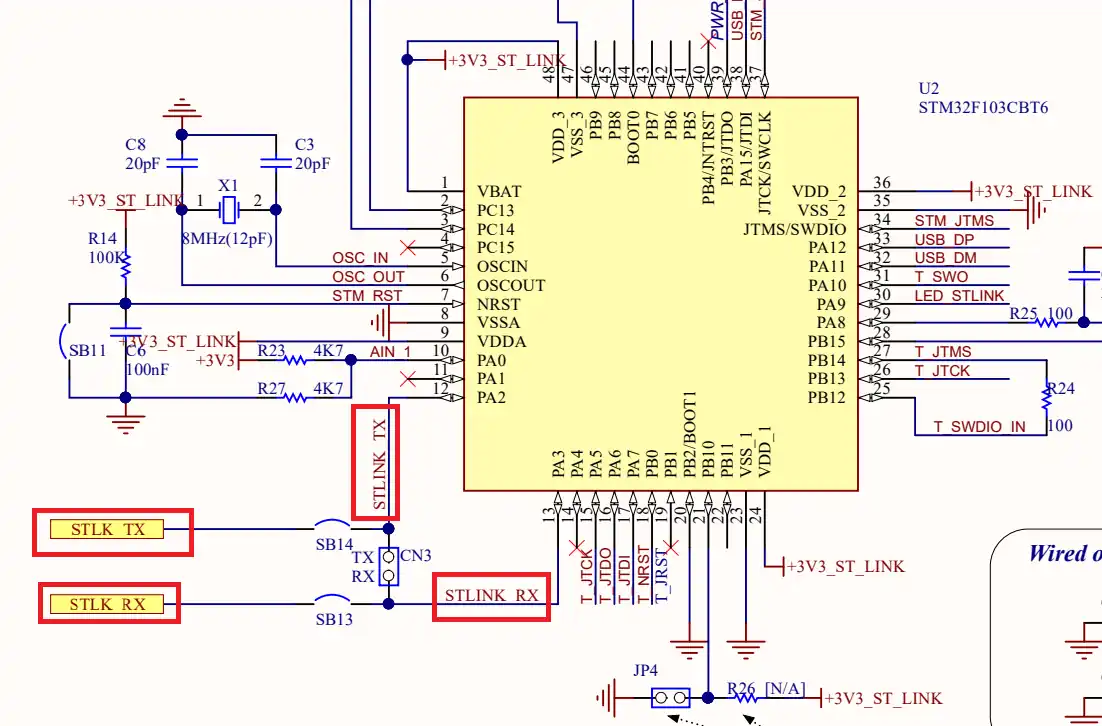
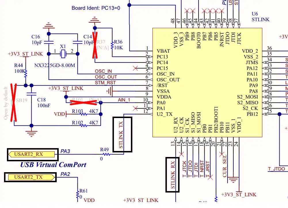
As you can see in the images above, both Nucleo F446RE and Discovery F412 supports the USB Virtual Com Port. So if you are using either of these boards, you do not need to use an additional module to communicate to the computer. The USB used for the ST link can also be used for the communication.
Not all the boards support this Virtual Com port feature. Below is the image from the schematic of the very famous STM32F4 Discovery board.
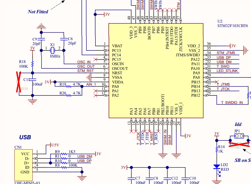
As you can see in the image above, there is no virtual com port in the F4 Discovery board. In such cases we can use some module to convert the UART signals to the USB, which is connected to the computer.
UART Connection using USB-TTL Converter
The Blue Pill does not come with an onboard USB-UART interface. To communicate with a PC, connect a USB-TTL converter (like FTDI, CH340, or CP2102) to USART1.
The image below shows the connection between the MCU and the FT232 USB to UART converter.
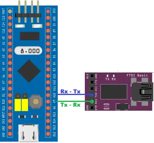
The UART is always connected in the cross connection, connecting the TX pin of the MCU to the RX of the device and the RX to the TX of the device. The module then connects to the computer using the USB.
Important points:
- Always cross TX ↔ RX.
- Make sure both devices share GND.
- Use 5V or 3.3V from the USB-TTL depending on your board’s power setup.
Once connected, plug the USB-TTL into your PC and open a serial terminal at 115200 baud to view the UART output.
Pin Mapping Table for Both Boards
The table below shows the exact UART pins used in this tutorial:
| Board | UART Peripheral | TX Pin | RX Pin | Connection to PC |
|---|---|---|---|---|
| Nucleo-F446RE | USART2 | PA2 | PA3 | Virtual COM Port (built-in) |
| STM32F103C8 | USART1 | PA9 | PA10 | USB-TTL converter (FTDI/CH340) |
These pins work for all basic UART transmit examples in this series.
UART Setup in STM32CubeMX (LL Drivers)
STM32CubeMX makes the initial setup simple by generating the basic project structure for us. Since CubeMX handles the boilerplate code, the focus here is only on the UART configuration needed for transmitting data using LL drivers. Once UART is enabled and configured, we can directly start writing code in the main file.
STM32 Clock Configuration
Before generating the project, we must configure the system clock. Open the Clock Configuration tab in CubeMX.
For the STM32F446RE, we will use the 8 MHz external crystal in bypass mode. This is the default clock source on the Nucleo board. The bypass mode uses the clock from the on-board ST-Link MCU.
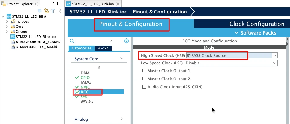
We will feed this into the PLL and run the system at 180 MHz, which is the maximum frequency for this MCU.
The image below shows the complete PLL and clock configuration used to achieve 180 MHz.
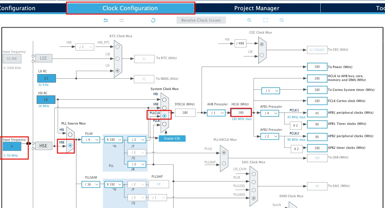
This fast system clock ensures accurate delays and smooth blinking using LL drivers. The SysTick timer will also run from this 180 MHz system clock, which becomes important in the delay functions we will use later.
Note for STM32F103C8:
This MCU uses an 8 MHz external crystal as well, but its maximum frequency is 72 MHz. If you are using the Blue Pill, configure the PLL so that the final system clock is 72 MHz.
Enabling USART2 for Nucleo-F446 VCP
Nucleo boards come with an onboard ST-Link debugger that also provides a Virtual COM Port (VCP). This VCP is connected internally to USART2, making it a great choice for UART communication without additional hardware.
The image below shows the USART2 configuration in the CubeMX.
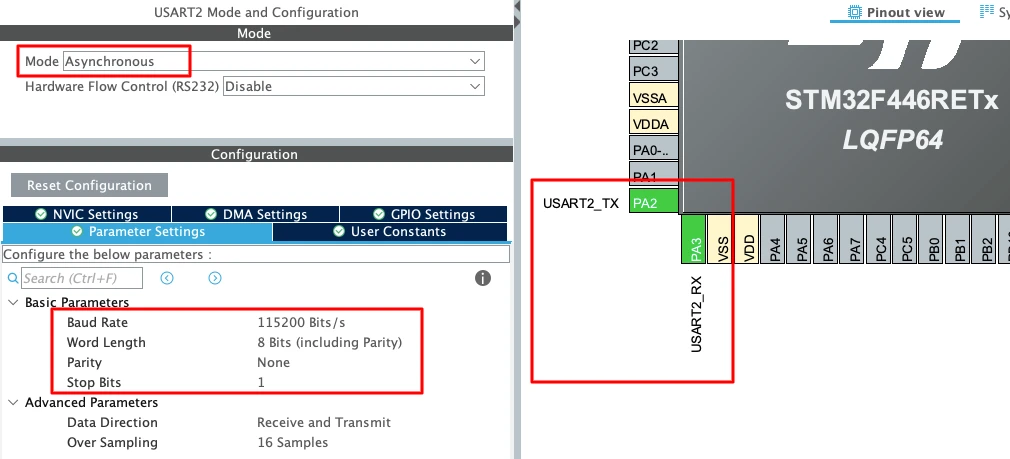
To enable USART2 in CubeMX:
- Open Connectivity -> USART2.
- Set the Mode to Asynchronous.
- CubeMX automatically assigns the correct pins:
- PA2 -> TX
- PA3 -> RX
- Keep the Baud Rate to a common value like 115200.
Enabling USART1 for STM32F103C8
For the STM32F103C8 (Blue Pill), USART1 is the most commonly used UART port because the pins are easy to access. The image below shows the USART1 configuration in the CubeMX.
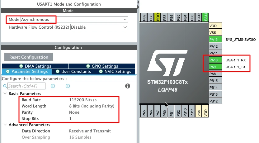
To enable USART1 in CubeMX:
- Open Connectivity -> USART1.
- Set the Mode to Asynchronous.
- The default pin mapping is:
- PA9 -> TX
- PA10 -> RX
- Use a standard 115200 baud rate for smooth communication.
This UART will later connect to a USB-TTL converter, which links the board to your PC. The connection is already explained above, connecting the pin PA9 -> RX of the module and PA10 -> TX of the module.
Important UART Configuration Parameters
When setting up UART for basic transmit, a few key parameters must be selected correctly:
- Baud Rate
Defines how fast the data is sent.
Common values: 9600, 57600, 115200.
For logs and debugging, 115200 works best. - Word Length
Use 8 Bits for normal communication. - Stop Bits
Set this to 1 Stop Bit. - Parity
Keep it None unless required by a special protocol. - Hardware Flow Control
Disable it. (None)
These settings ensure compatibility with most serial terminals and USB-TTL adapters, keeping the communication stable and predictable.
UART Transmit in Polling Mode using LL APIs
Polling mode is the simplest way to send data through UART using LL drivers. In this mode, the CPU waits for specific UART status flags before sending each byte. This gives full control over the transmit process and helps you understand exactly how the UART hardware works.
For this tutorial, only three LL functions are used. These functions keep the code clean, predictable, and easy to follow.
LL_USART_IsActiveFlag_TXE: Why This Flag Matters
Before sending a byte, we must check if the UART transmit register is empty. The TXE (Transmit Data Register Empty) flag tells us exactly that.
- TXE = 1 -> Ready to send the next byte
- TXE = 0 -> UART is still busy
The LL function used:
LL_USART_IsActiveFlag_TXE(USARTx);This ensures we never overwrite data in the transmit buffer. Waiting for TXE is the most important step in safe and reliable UART communication.
LL_USART_TransmitData8: Sending One Byte
When TXE becomes set, we can safely place a new byte into the transmit register using:
LL_USART_TransmitData8(USARTx, data);Here, data is an 8-bit value (a char). This function writes the byte into the UART hardware, and transmission begins instantly.
This is the core function for sending characters, logs, or any form of data.
LL_USART_IsActiveFlag_TC: Waiting for Transmission to Finish
After writing the byte, we must ensure the entire frame has actually left the UART line.
The TC (Transmission Complete) flag confirms this.
- TC = 1 -> Last bit of the byte is fully transmitted
- This avoids cutting off data when sending strings or ending a transfer
The LL function:
LL_USART_IsActiveFlag_TC(USARTx);Waiting for this flag ensures a clean and complete UART transmission.
LL UART Functions Used
The Table below explains the functions we are using to transmit the data via UART.
| Function Name | Description |
|---|---|
| LL_USART_IsActiveFlag_TXE(USARTx) | Checks if the TXE (Transmit Data Register Empty) flag is set. Used to confirm UART is ready for the next byte. |
| LL_USART_TransmitData8(USARTx, data) | Sends a single 8-bit data value by writing it to the UART transmit register. |
| LL_USART_IsActiveFlag_TC(USARTx) | Checks if the TC (Transmission Complete) flag is set. Confirms that the entire frame has been transmitted. |
Complete UART Transmit Function Example
Below is a clean and practical UART transmit function that sends an entire string using only the required LL functions (TXE, TransmitData8, and TC). This version avoids calling a separate SendChar function and handles everything inside one loop.
void uart_send (char *data)
{
    while (*data)
    {
        while (!LL_USART_IsActiveFlag_TXE(USART2));   // Wait until TX buffer is empty
        LL_USART_TransmitData8(USART2, *data++);      // Transmit next byte
    }

    while (!LL_USART_IsActiveFlag_TC(USART2));        // Wait for final transmission to complete
}This function is efficient, simple, and ensures that every byte is fully transmitted before returning.
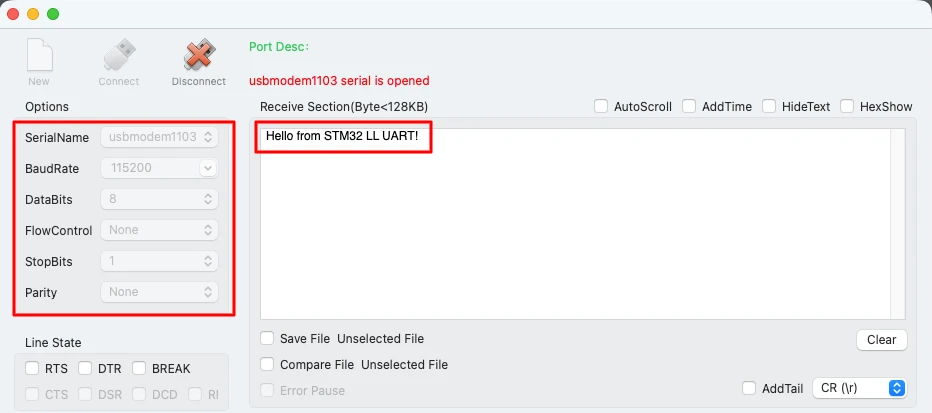
Example: Sending a Text String Over UART
Using the function is straightforward. Just pass the string you want to send:
uart_send("Hello from STM32 LL UART!\r\n");The image below shows the expected UART output on the serial terminal.
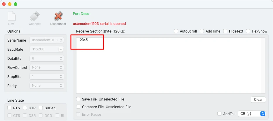
Example: Sending Numbers Over UART
To transmit integers or any numeric value over UART, first convert the number into a string and then reuse the same uart_send() function. The standard sprintf() or itoa() method works well for this.
#include <stdio.h>

int num = 12345;
char buffer[16];
sprintf(buffer, "%d", num);   // Convert number to string
uart_send(buffer);
uart_send ("\r\n");The image below shows the expected UART output on the serial terminal.
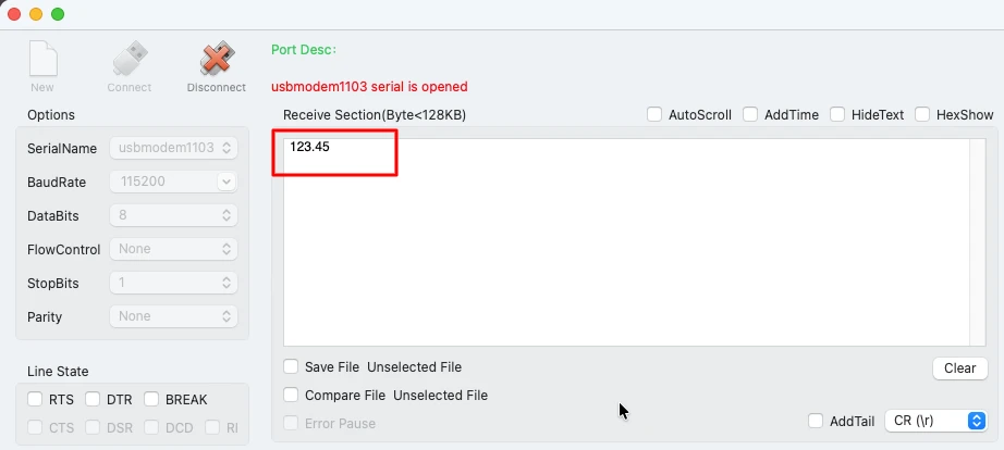
Sending a Float
The float values should be sent similar to integer values. Before sending float values using sprintf(), enable floating-point support for printf:
Enable printf float support in STM32CubeIDE
- Right-click your project → Properties
- Go to C/C++ Build → Settings
- Under MCU/MPU Settings, enable
-u _printf_float
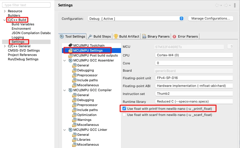
Now floats will format correctly.
You can send the floats in the similar way as we sent the integers.
#include <stdio.h>

float num = 123.45;
char buffer[16];
sprintf(buffer, "%.2f", num);   // Convert float to string
uart_send(buffer);
uart_send ("\r\n");The image below shows the output on the console.
Implementing printf using int _write()
Using printf() in embedded projects makes debugging easier. Instead of sending characters manually, we can redirect all standard output (stdout) to UART. This allows printf() to print directly to the serial terminal, just like on a PC.
Below are the steps to understand why and how to implement this.
Why Redirect printf to UART?
printf() normally sends data to the system console, which does not exist on microcontrollers. By overriding the low-level _write() function, all printf() output is forwarded to the UART peripheral.
Benefits:
- Cleaner and shorter debugging code
- Easy logging of integers, floats, and formatted text
- Helps during testing and real-time monitoring
- Works with any UART port configured in LL mode
Once redirected, you can simply write:
printf("System running...\r\n");And the message appears on your serial terminal.
Code for int _write() Function
Here is a simple and reliable _write() implementation using your existing uart_send() function:
int _write(int file, char *ptr, int len)
{
    for (int i = 0; i < len; i++)
    {
        while (!LL_USART_IsActiveFlag_TXE(USART2));  // Wait for TX buffer
        LL_USART_TransmitData8(USART2, ptr[i]);      // Send byte
    }

    while (!LL_USART_IsActiveFlag_TC(USART2));        // Wait for complete transmission
    return len;
}Notes:
- This example uses USART2 (Nucleo-F446 VCP).
- Replace with USART1 if using STM32F103C8 and USB-TTL.
Testing printf Output on Serial Terminal
After implementing _write(), you can directly call printf() anywhere in your project. The code below shows the data in different formats being sent by using printf.
printf("Hello from STM32!\r\n");
printf("Value = %d\r\n", 42);
printf("Temperature = %.2f C\r\n", 36.75f);The image below shows how the serial terminal displays the formatted data.
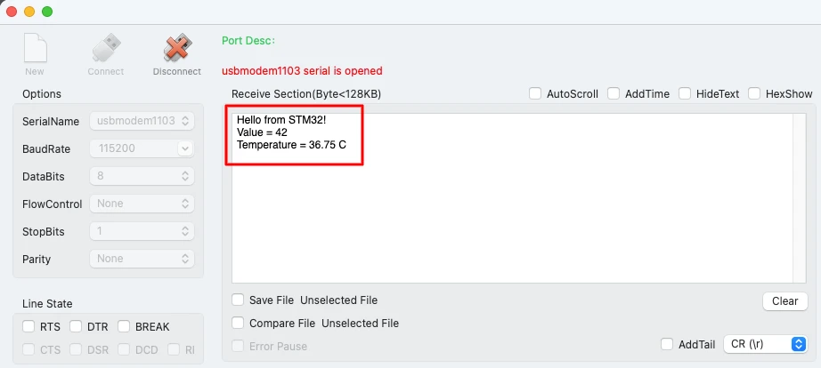
This completes the setup for redirecting standard C output to UART, making your debugging workflow much faster and cleaner.
Advantages of UART with LL Over HAL
Using the STM32 LL (Low-Layer) drivers provides several strong advantages over the HAL layer, especially for UART communication. LL offers a faster, lighter, and more predictable way to work with the hardware, making it ideal for performance-critical projects.
Below are the key benefits.
Faster Execution and Lower Latency
LL functions interact almost directly with hardware registers.
This means:
- Less function overhead
- Faster execution compared to HAL
- Reduced latency during UART transmission
When working in polling mode, LL helps transmit bytes with minimal delay, which is very helpful in real-time applications.
Smaller Flash Footprint
HAL includes layers of abstraction, error handling, and extra features.
LL is lean and minimal.
Because of this:
- Code size is much smaller
- More Flash is available for your own logic
- Ideal for smaller MCUs like STM32F103C8
If your project needs to stay light and fast, LL is a perfect fit.
More Control Over Hardware
LL gives you fine-grained control of peripheral registers without full manual register programming.
Advantages include:
- Precise handling of UART flags (TXE, TC, RXNE, etc.)
- Ability to optimize timing
- Complete control of when data is pushed or read
This makes LL great for applications that need both performance and predictability.
Predictable Timing for Real-Time Systems
HAL includes delays, state checks, and additional abstraction layers.
This adds jitter and unpredictability.
With LL:
- You know exactly how many instructions each operation takes
- Polling loops behave consistently
- Timing becomes stable, which is crucial for real-time tasks
Projects involving motor control, real-time sensors, or communication protocols benefit heavily from the predictable behavior LL offers.
Conclusion
This tutorial introduced UART transmit using STM32 LL drivers in a clear and practical way. You learned how to configure UART in STM32CubeMX, make the correct hardware connections for both Nucleo-F446RE and STM32F103C8, and use essential LL functions like LL_USART_IsActiveFlag_TXE, LL_USART_IsActiveFlag_TC, and LL_USART_TransmitData8. We also built clean helper functions for sending characters, strings, integers, and floats, and even redirected printf() output using the _write() function. These tools form a strong foundation for efficient and readable UART communication.
By working with LL instead of HAL, you gained a faster, lighter, and more predictable style of coding. This approach is very useful for debugging, real-time monitoring, and low-level control in performance-critical projects. The ability to send logs, sensor values, or formatted messages directly to the serial terminal makes development smoother and much easier to troubleshoot.
In the next part of this UART series, we will move beyond polling mode and explore UART communication using interrupts. This allows non-blocking transmission and reception, making your applications more responsive and efficient.
Browse More STM32 LL Tutorials
STM32 LL GPIO Input and EXTI Interrupt Tutorial: Read Buttons With Low-Level Drivers
STM32 UART using LL Drivers (Part 2): Transmit using Interrupt & DMA
STM32 UART using LL Drivers (Part 3): Receive Data in Blocking Mode
STM32 UART using LL Drivers (Part 4): Receive Data in Interrupt Mode
STM32 UART using LL Drivers (Part 5): Receive Using DMA (Normal and Circular Mode)
STM32 ADC Using LL Drivers (Part 1): Single Channel Blocking and Interrupt Mode

STM32 ADC Using LL Drivers (Part 2): Multiple Channels using DMA Mode
STM32 LL UART Project Download
STM32 LL UART FAQs
Subscribe
Login
0 Comments
Newest
