
Published: December 20, 2025
Last Updated: March 25, 2026
Last Updated: March 25, 2026
STM32 UART Transmit using LL Drivers (Interrupt & DMA)
UART is one of the most widely used communication interfaces in STM32 microcontrollers. It is commonly used for debugging, logging, and data exchange. In Part 1 of this series, we learned how to transmit UART data using polling mode with STM32 LL drivers. That tutorial is a prerequisite for this post, as it introduces the basic UART setup and LL driver usage.
In this tutorial, we move to more efficient methods. We will transmit UART data using interrupt and DMA with STM32 LL drivers. These methods allow the CPU to perform other tasks while data is being sent. We will first understand why polling is not enough, then learn how UART interrupts and DMA work, and finally implement both methods using simple code examples and full working code.
Why Polling Is Not Enough for UART Transmission
Polling is the simplest way to use UART. The CPU continuously checks the UART status flags and sends data when the hardware is ready. This method works well for learning and small tests. However, as applications grow, polling starts to create serious limitations.
Why Polling is an issue
In polling mode, the CPU waits in a loop until the UART is ready to send the next byte. It keeps checking flags like TXE and TC again and again. While the CPU is polling, it cannot do any other useful work.
Even simple tasks like reading sensors, updating displays, or handling timers get delayed. This wastes CPU time and reduces overall system performance.
Polling may look harmless in small examples, but it creates problems in real applications. As the project grows, multiple peripherals need attention at the same time.
Using polling:
- The CPU stays busy unnecessarily
- Timing becomes unpredictable
- Power consumption increases
- The code becomes harder to scale
When Polling Can Still Be Used
Polling is not always bad. It is still useful in very simple applications where UART data is sent rarely.
Polling works well for:
- Early learning and testing
- Quick debug prints during bring-up
- Very small programs with no timing constraints
Once the project becomes more complex, polling should be replaced with interrupt or DMA-based UART transmission.
Why We Need UART Interrupts in STM32
Polling keeps the CPU busy and limits performance. UART interrupts solve this problem by allowing the hardware to notify the CPU only when attention is needed. Instead of waiting in a loop, the CPU continues executing other code. When the UART is ready to send data or has fully completed a transmission, an interrupt is triggered. This makes UART communication more efficient and suitable for real applications.
An interrupt is a hardware signal that temporarily stops normal program execution and moves the CPU to a special function called an interrupt handler. In UART transmission, interrupts are generated when the transmit data register becomes empty or when the entire transmission is fully completed. The CPU reacts only when these events occur, which removes the need for continuous flag checking.
TXE and TC Flags Explained
UART transmission mainly uses two important flags. Both flags play a key role in interrupt-based UART transmission.
- The TXE (Transmit Data Register Empty) flag indicates that the UART is ready to accept a new byte.
When TXE becomes active, the next data byte can be written safely.
- The TC (Transmission Complete) flag indicates that the last byte has fully left the shift register.
This means all bits, including the stop bit, are sent on the UART line.
UART Transmission flow Using Interrupts
The interrupt-based UART transmission follows a simple flow.
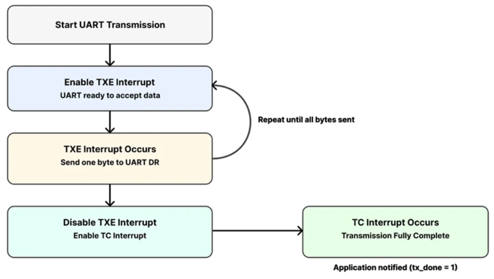
- First, the application starts the transmission and enables the TXE interrupt.
Each time TXE occurs, one byte is sent to the UART data register.
- After the last byte is loaded, the TXE interrupt is disabled.
Then the TC interrupt is enabled to detect when transmission is fully complete.
- Once TC is triggered, the UART transmission ends.
The application is notified that sending data is finished.
UART Interrupt Setup in STM32CubeMX (LL Drivers)
We have already covered the basic UART configuration in the PART1 of this uart series, therefore, here we will just focus on the interrupt section.
Enabling USART2 Interrupt for Nucleo-F446
Nucleo boards come with an onboard ST-Link debugger that also provides a Virtual COM Port (VCP). This VCP is connected internally to USART2, making it a great choice for UART communication without additional hardware.
The image below shows the USART2 configuration in the CubeMX.
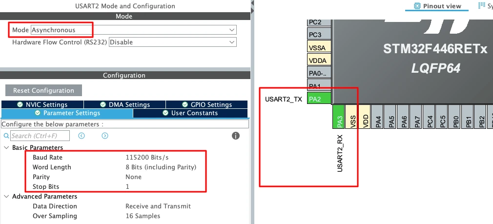
To enable USART2 in CubeMX:
- Open Connectivity -> USART2.
- Set the Mode to Asynchronous.
- CubeMX automatically assigns the correct pins:
- PA2 -> TX
- PA3 -> RX
- Keep the Baud Rate to a common value like 115200.
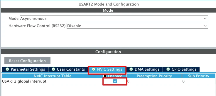
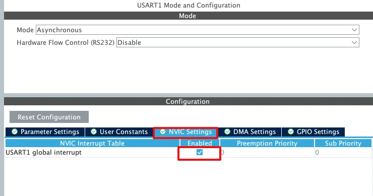
Now enable the USART2 interrupt in the NVIC tab as shown in the image below.
Enabling USART1 Interrupt for STM32F103C8
For the STM32F103C8 (Blue Pill), USART1 is the most commonly used UART port because the pins are easy to access. The image below shows the USART1 configuration in the CubeMX.
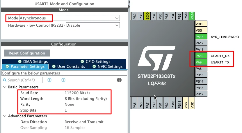
To enable USART1 in CubeMX:
- Open Connectivity -> USART1.
- Set the Mode to Asynchronous.
- The default pin mapping is:
- PA9 -> TX
- PA10 -> RX
- Use a standard 115200 baud rate for smooth communication.
Enable the USART1 interrupt in the NVIC tab as shown in the image below.
Important UART Configuration Parameters
When setting up UART for basic transmit, a few key parameters must be selected correctly:
- Baud Rate
Defines how fast the data is sent.
Common values: 9600, 57600, 115200.
For logs and debugging, 115200 works best. - Word Length
Use 8 Bits for normal communication. - Stop Bits
Set this to 1 Stop Bit. - Parity
Keep it None unless required by a special protocol. - Hardware Flow Control
Disable it. (None)
STM32 UART Transmission Using Interrupt (LL Drivers)
Now that we understand why UART interrupts are needed, we can move to the implementation. In this section, we will transmit UART data using TXE and TC interrupts with STM32 LL drivers.
We will first look at the variables required for interrupt-based transmission. Then we will understand how the transmit function and interrupt handler work together.
Global Variables Used for Interrupt Transmission
Interrupt-based UART transmission needs some global variables to track the data and its progress.
uint8_t *tx_buf = 0;
volatile uint16_t tx_len;
volatile uint16_t tx_index;
volatile int tx_done = 0;- Here,
tx_bufstores the pointer to the transmit buffer. tx_lenholds the total number of bytes to send.tx_indexkeeps track of the current byte being transmitted.- The
tx_doneflag is used to indicate when transmission is complete.
These variables are shared between the main code and the interrupt handler.
UART_Send_IT Function Explained
This function starts the UART transmission using interrupts.
void UART_Send_IT(uint8_t *buf, uint16_t len)
{
tx_buf = buf;
tx_len = len;
tx_index = 0;
tx_done = 0;
LL_USART_ClearFlag_TC(USART2); // VERY IMPORTANT
LL_USART_EnableIT_TXE(USART2);
}- First, the transmit buffer and length are stored in global variables. The index is reset, and the completion flag is cleared.
- The TC flag is cleared before enabling interrupts. This step is very important, as TC might still be set from a previous transmission.
- Finally, the TXE interrupt is enabled. This allows the UART to request the CPU whenever it is ready to accept a new byte.
USART Interrupt Handler Logic
The actual data transmission happens inside the UART interrupt handler. You must define this function in the stm32f4xx_it.c file, inside the USART2_IRQHandler(). When the interrupt is triggered, the USART2_IRQHandler() is called, and here we will call USART2_Handler() to handle this interrupt ourselves.
void USART2_Handler(void)
{
if (LL_USART_IsActiveFlag_TXE(USART2) && LL_USART_IsEnabledIT_TXE(USART2))
{
if (tx_index < tx_len)
{
LL_USART_TransmitData8(USART2, tx_buf[tx_index++]);
if (tx_index == tx_len)
{
LL_USART_DisableIT_TXE(USART2);
LL_USART_EnableIT_TC(USART2);
}
}
}
if (LL_USART_IsActiveFlag_TC(USART2) && LL_USART_IsEnabledIT_TC(USART2))
{
LL_USART_ClearFlag_TC(USART2);
LL_USART_DisableIT_TC(USART2);
tx_done = 1;
}
}When the TXE interrupt occurs, one byte is written to the UART data register. This continues until all bytes are loaded. After the last byte is sent, the TXE interrupt is disabled an then the TC interrupt is enabled to detect when the final bit is transmitted.
When the TC interrupt occurs, the transmission is fully complete, hence the tx_done flag is set to notify the application.
Sending Data from main() Using Interrupt
In the main loop, we can now send data using the interrupt-based function.
int len = sprintf((char *)buffer, "Hello %d\r\n", count++);
UART_Send_IT(buffer, len);Here, sprintf() formats the message into a buffer. The buffer is then passed to UART_Send_IT() to start transmission. The CPU remains free while the data is being transmitted in the background.
Note:
For the STM32F103C8, the interrupt-based UART transmission logic remains largely the same as the code
written for the Nucleo-F446. The main difference lies in the DMA and interrupt configuration at the
hardware level, while the overall flow and handling of the transmission complete interrupt remain
unchanged.
Complete Interrupt-Based UART Transmission Code
Below is the full combined code for UART transmission using interrupts and STM32 LL drivers.
uint8_t *tx_buf = 0;
volatile uint16_t tx_len;
volatile uint16_t tx_index;
volatile int tx_done = 0;
void UART_Send_IT(uint8_t *buf, uint16_t len)
{
tx_buf = buf;
tx_len = len;
tx_index = 0;
tx_done = 0;
LL_USART_ClearFlag_TC(USART2);
LL_USART_EnableIT_TXE(USART2);
}
void USART2_Handler(void)
{
    if (LL_USART_IsActiveFlag_TXE(USART2) && LL_USART_IsEnabledIT_TXE(USART2))
    {
        if (tx_index < tx_len)
        {
            LL_USART_TransmitData8(USART2, tx_buf[tx_index++]);

            if (tx_index == tx_len)
            {
                LL_USART_DisableIT_TXE(USART2);
                LL_USART_EnableIT_TC(USART2);
            }
        }
    }

    if (LL_USART_IsActiveFlag_TC(USART2) && LL_USART_IsEnabledIT_TC(USART2))
    {
        LL_USART_ClearFlag_TC(USART2);
        LL_USART_DisableIT_TC(USART2);
        tx_done = 1;
    }
}
int count = 0;
uint8_t buffer[64];
int main()
{
....
....
while (1)
{
int len = sprintf((char *)buffer, "Hello %d\r\n", count++);
UART_Send_IT(buffer, len);
LL_mDelay(1000);
}
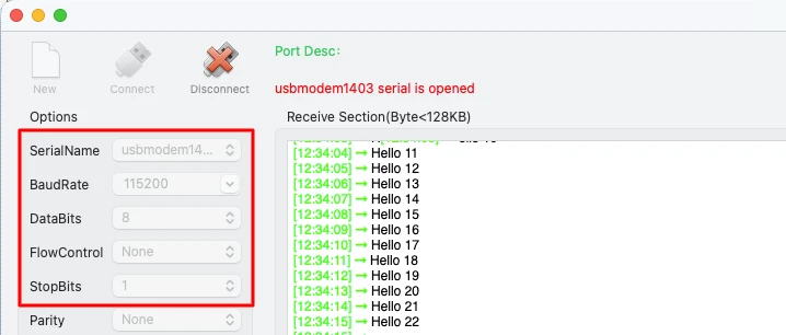
}Output Using UART Interrupt Mode
The image below shows the UART output printed repeatedly on a serial terminal. The counter value increases every second, confirming that data is transmitted correctly using UART interrupt mode.
Why We Need DMA for UART Transmission
Interrupt-based UART transmission is efficient, but it still requires CPU involvement for every byte. When the data size increases, interrupt overhead also increases. Interrupt-based UART works well for small and medium data sizes. However, it still interrupts the CPU for every transmitted byte.
This causes:
- Reduced efficiency for large buffers
- High interrupt frequency
- Increased CPU load
This is where DMA becomes important. DMA allows data to move from memory to UART without CPU intervention. The CPU only configures DMA once and gets notified when the transfer is complete.
What Is DMA and How It Works
DMA stands for Direct Memory Access. It is a hardware block that transfers data between memory and peripherals.
For UART transmission, DMA:
- Reads data directly from memory
- Writes it to the UART data register
- Works in the background without CPU involvement
The CPU only starts the DMA transfer and waits for a completion interrupt.
Flow of UART Transmission Using DMA
The DMA-based UART transmission follows a simple flow.
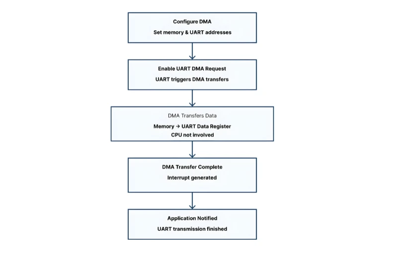
- First, the application configures the DMA stream with memory and UART addresses.
Then the UART DMA request is enabled.
- DMA starts transferring data from memory to the UART data register.
The CPU is not involved during the transfer.
- Once all data is transmitted, a DMA transfer complete interrupt occurs.
The application is notified that UART transmission has finished.
UART DMA Setup in STM32CubeMX
Inside CubeMX, the DMA configuration appears similar for both the STM32F103C8 and STM32F446RE MCUs. However, there are important differences at the DMA hardware level, and these differences affect how the DMA must be programmed in firmware.
Enabling USART2 DMA for Nucleo-F446
The image below shows the TX DMA enabled for Nucleo-F446RE.
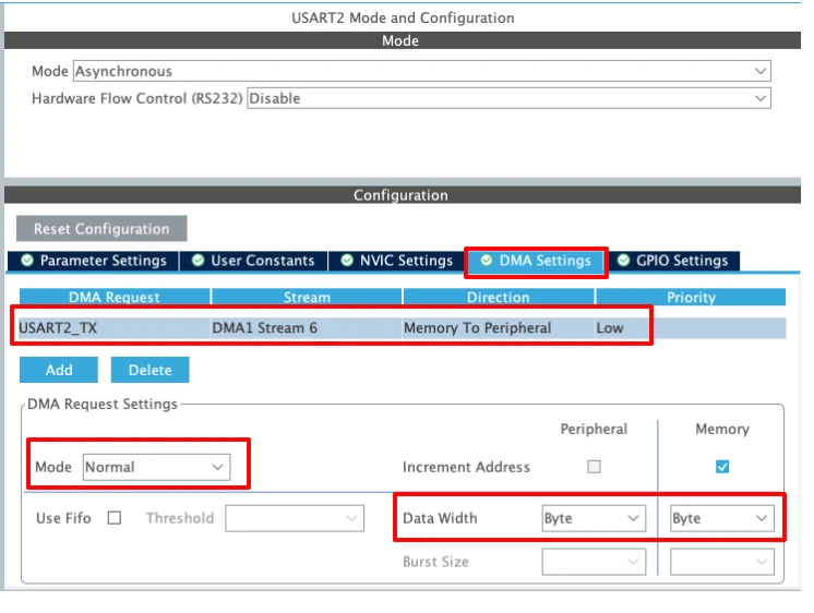
1. DMA Request selection
The DMA Request is set to USART2_TX, which means this DMA stream will be triggered automatically whenever USART2 needs to transmit data. This links the DMA controller directly to the USART2 transmit register.
2. DMA Stream and Direction
- DMA1 Stream 6 is selected for USART2 TX (as per STM32F4 DMA mapping).
- Direction: Memory to Peripheral
This is essential for UART transmission, because data flows from a memory buffer (RAM) to the USART data register.
3. DMA Mode
- Mode: Normal
In Normal mode, the DMA transfers the specified number of bytes and then stops automatically.
This mode is typically used for sending packets or strings over UART.
(Circular mode is more suitable for continuous or repeated transfers.)
4. Increment Address settings
- Peripheral increment: Disabled
The USART data register address must remain fixed. - Memory increment: Enabled
This allows the DMA to read consecutive bytes from the transmit buffer in memory.
5. Data Width
- Peripheral data width: Byte
- Memory data width: Byte
UART transmits data one byte at a time, so both widths must be set to Byte.
Any mismatch here can lead to corrupted or failed transmissions.
6. Priority
- Priority: Low
UART transmission usually does not require high priority. This can be increased if DMA contention exists with other peripherals.
Enabling USART1 DMA for F103C8
The DMA configuration will remain pretty much the same as we saw in Nucleo-F446. The image below shows the DMA configuration for STM32F103C8.
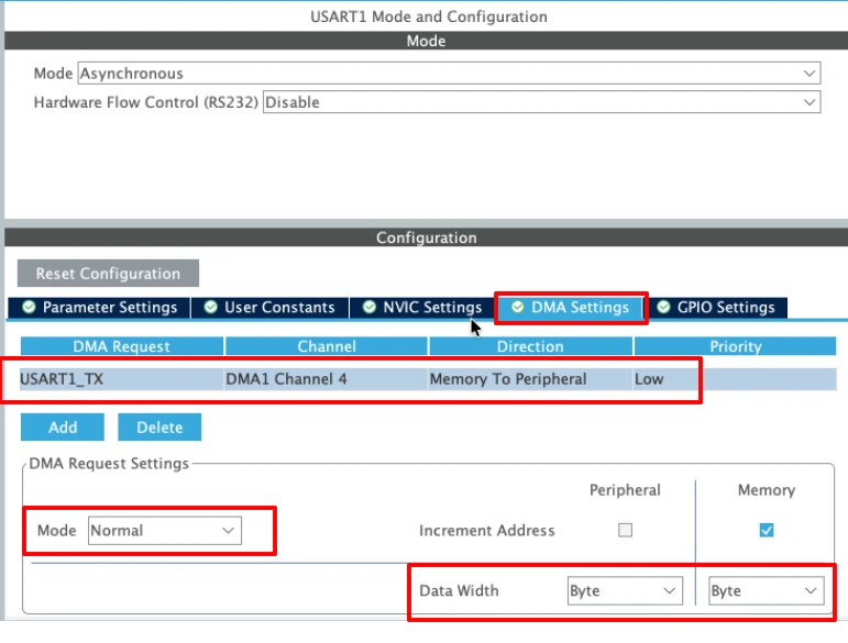
The configuration remains the same as that of the Nucleo-F446. However, note that in this case the DMA uses channels, whereas the Nucleo board uses streams. This difference arises from the underlying DMA architecture of the MCU family and affects how the DMA is configured and programmed in firmware.
STM32 UART Transmission Using DMA (LL Drivers)
DMA makes UART transmission much more efficient by transferring data directly from memory to the UART peripheral. In this section, we will implement UART transmission using DMA with STM32 LL drivers.
UART_Send_DMA Function Explained
The UART_Send_DMA function starts the UART transmission using DMA.
void UART_Send_DMA(uint8_t *buf, uint16_t len)
{
    tx_done = 0;

    LL_DMA_DisableStream(DMA1, LL_DMA_STREAM_6);

    LL_DMA_SetPeriphAddress(DMA1, LL_DMA_STREAM_6, LL_USART_DMA_GetRegAddr(USART2));
    LL_DMA_SetMemoryAddress(DMA1, LL_DMA_STREAM_6, (uint32_t)buf);
    LL_DMA_SetDataLength(DMA1, LL_DMA_STREAM_6, len);

    LL_USART_ClearFlag_TC(USART2);
    LL_USART_EnableDMAReq_TX(USART2);

    LL_DMA_EnableIT_TC(DMA1, LL_DMA_STREAM_6);
    LL_DMA_EnableStream(DMA1, LL_DMA_STREAM_6);
}Here’s what happens step by step:
- Disable DMA stream to ensure it is ready for a new transfer.
- Set the peripheral (UART) and memory addresses and the data length.
- Clear the TC flag in the UART to avoid conflicts.
- Enable the UART DMA request so that UART can request data from DMA.
- Enable DMA transfer complete interrupt and start the DMA stream.
Once started, the DMA controller automatically moves data from memory to UART without CPU involvement.
DMA Interrupt Handler for UART Transmission
The DMA interrupt handler detects when the transfer is complete and notifies the application. You must define this function in the stm32f4xx_it.c file, inside the DMA1_Stream6_IRQHandler(). When the DMA finishes the transfer, an interrupt is triggered and the DMA1_Stream6_IRQHandler() is called. Here we will call USART_DMA_IRQHandler() to handle this interrupt ourselves.
void USART_DMA_IRQHandler(void)
{
if (LL_DMA_IsActiveFlag_TC6(DMA1))
{
LL_DMA_ClearFlag_TC6(DMA1);
LL_DMA_DisableStream(DMA1, LL_DMA_STREAM_6);
tx_done = 1;
}
}When the DMA transfer complete flag is set, the stream is disabled and tx_done is set to 1. This informs the main application that the transmission is finished.
Sending Data from main() Using DMA
Using DMA is simple in the main loop:
int len = sprintf((char *)buffer, "Hello %d\r\n", count++);
UART_Send_DMA(buffer, len);Here, sprintf() formats the message into a buffer. UART_Send_DMA() then triggers the DMA transfer, sending the data in the background.
The CPU can continue executing other tasks while the transfer is in progress.
Full STM32 UART DMA Example Code
uint8_t buffer[64];
int count = 0;
volatile int tx_done = 0;
void UART_Send_DMA(uint8_t *buf, uint16_t len)
{
    tx_done = 0;

    LL_DMA_DisableStream(DMA1, LL_DMA_STREAM_6);

    LL_DMA_SetPeriphAddress(DMA1, LL_DMA_STREAM_6, LL_USART_DMA_GetRegAddr(USART2));
    LL_DMA_SetMemoryAddress(DMA1, LL_DMA_STREAM_6, (uint32_t)buf);
    LL_DMA_SetDataLength(DMA1, LL_DMA_STREAM_6, len);

    LL_USART_ClearFlag_TC(USART2);
    LL_USART_EnableDMAReq_TX(USART2);

    LL_DMA_EnableIT_TC(DMA1, LL_DMA_STREAM_6);
    LL_DMA_EnableStream(DMA1, LL_DMA_STREAM_6);
}
void USART_DMA_IRQHandler(void)
{
    if (LL_DMA_IsActiveFlag_TC6(DMA1))
    {
        LL_DMA_ClearFlag_TC6(DMA1);
        LL_DMA_DisableStream(DMA1, LL_DMA_STREAM_6);

        tx_done = 1;
    }
}
int main()
{
....
....
while (1)
{
int len = sprintf((char *)buffer, "Hello %d\r\n", count++);
UART_Send_DMA(buffer, len);
LL_mDelay(1000);
}
} This code demonstrates efficient UART transmission using DMA with STM32 LL drivers. It allows large data transfers while keeping the CPU free for other tasks.
Output Using UART DMA Mode
The UART data appears on the serial terminal just like with interrupts. The counter increments every second, confirming that the DMA transfer is working correctly.
Compared to interrupts, CPU usage is lower, and the application can perform other tasks seamlessly.
What changes in STM32F103C8?
As shown in the configuration, the STM32F103C8 relies on DMA channels instead of streams. Hence, the only modification needed is to switch from stream-based DMA handling to channel-based handling.
Below is the full code to transmit the data via USART DMA in STM32F103C8.
uint8_t buffer[64];
int count = 0;
volatile int tx_done = 0;
void UART_Send_DMA(uint8_t *buf, uint16_t len)
{
tx_done = 0;
LL_DMA_DisableChannel(DMA1, LL_DMA_CHANNEL_4);
LL_DMA_SetPeriphAddress(DMA1, LL_DMA_CHANNEL_4, LL_USART_DMA_GetRegAddr(USART1));
LL_DMA_SetMemoryAddress(DMA1, LL_DMA_CHANNEL_4, (uint32_t)buf);
LL_DMA_SetDataLength(DMA1, LL_DMA_CHANNEL_4, len);
LL_USART_ClearFlag_TC(USART1);
LL_USART_EnableDMAReq_TX(USART1);
LL_DMA_EnableIT_TC(DMA1, LL_DMA_CHANNEL_4);
LL_DMA_EnableChannel(DMA1, LL_DMA_CHANNEL_4);
}
void USART_DMA_IRQHandler(void)
{
if (LL_DMA_IsActiveFlag_TC4(DMA1))
{
LL_DMA_ClearFlag_TC4(DMA1);
LL_DMA_DisableChannel(DMA1, LL_DMA_CHANNEL_4);
tx_done = 1;
}
}
int main()
{
....
....
while (1)
{
int len = sprintf((char *)buffer, "Hello %d\r\n", count++);
UART_Send_DMA(buffer, len);
LL_mDelay(1000);
}
} Apart from changing LL_DMA_STREAM_6 to LL_DMA_CHANNEL_4, there is essentially no other modification required. Also note that the functions LL_DMA_EnableChannel() and LL_DMA_DisableChannel() are used instead of their stream-based counterparts.
Interrupt vs DMA UART Transmission in STM32
In STM32 projects, both interrupt-based and DMA-based UART transmission are widely used. Each method has advantages and limitations. Understanding the differences helps you choose the right approach for your application.
CPU Usage Comparison
Interrupt-based UART transmits one byte at a time. Each byte triggers an interrupt, which consumes CPU cycles.
For small messages, this is fine. But as data size grows, CPU usage increases significantly.
DMA, on the other hand, transfers the entire buffer in the background. The CPU only configures DMA and gets notified when the transfer is complete.
This frees the CPU to run other tasks during transmission.
Data Size and Speed Considerations
| Feature | Interrupt Mode | DMA Mode |
|---|---|---|
| CPU Involvement | High (every byte triggers an interrupt) | Low (CPU not involved during transfer) |
| Best Data Size | Small to medium | Medium to large |
| Maximum Speed | Limited by interrupt latency | Higher throughput, efficient for long buffers |
| Complexity | Simple to implement | Slightly more setup (DMA config) |
| Power Efficiency | Lower, more CPU cycles | Higher, CPU idle during transfer |
| Use Case | Occasional debug prints, small messages | Continuous data streaming, large data transfers |
Which Method Should You Use
- Interrupt Mode:
Use it for small messages, debug prints, or when you want simple implementation.
Ideal for projects where timing is not critical and CPU load is not a concern. - DMA Mode:
Best for large buffers, high-speed UART, or RTOS-based applications.
Reduces CPU load and allows the microcontroller to handle multiple tasks efficiently.
In most real-world applications, DMA is preferred for heavy UART traffic, while interrupts are enough for lightweight communication.
Conclusion
In this tutorial, we learned how to transmit UART data on STM32 using interrupts and DMA with LL drivers. We started by understanding why polling is not efficient, then explored how TXE and TC interrupts allow the CPU to transmit data without blocking. Next, we saw how DMA further improves efficiency by transferring large buffers directly from memory to the UART peripheral while freeing the CPU. We also compared interrupt and DMA methods, highlighting their differences in CPU usage, data size handling, and real-world applications.
These methods are highly useful for building efficient and responsive STM32 applications. Interrupt-based UART is great for small messages and debug prints, while DMA-based transmission is ideal for high-speed communication and large data transfers. By implementing these techniques, your projects can handle UART communication smoothly, keep the CPU free for other tasks, and improve overall system performance.
Browse More STM32 LL Tutorials
STM32 LL GPIO Input and EXTI Interrupt Tutorial: Read Buttons With Low-Level Drivers
STM32 UART using LL Drivers (Part 1): Transmit using Polling Mode
STM32 UART using LL Drivers (Part 3): Receive Data in Blocking Mode
STM32 UART using LL Drivers (Part 4): Receive Data in Interrupt Mode
STM32 UART using LL Drivers (Part 5): Receive Using DMA (Normal and Circular Mode)
STM32 ADC Using LL Drivers (Part 1): Single Channel Blocking and Interrupt Mode
STM32 ADC Using LL Drivers (Part 2): Multiple Channels using DMA Mode
STM32 LL UART Project Download
STM32 LL UART FAQs
Subscribe
Login
0 Comments
Newest
