
Published: December 6, 2025
Last Updated: March 25, 2026
Last Updated: March 25, 2026
Getting Started With STM32 LL Drivers: Blink LED Using STM32CubeMX
Learning STM32 programming with Low-Layer Drivers can feel confusing at first. That is why this new tutorial series focuses on STM32 LL from the very beginning. The goal is to help you understand the basics in a simple way, and slowly move toward advanced peripherals like timers, UART, ADC, SPI, DMA, and more.
This is the first tutorial in the series, and we will start with the classic LED blinking example. It is simple, but it teaches you how LL drivers work, how CubeMX generates LL code, and how GPIO is handled at the register level.
Throughout this series, we will mainly use STM32F446RE and STM32F103C8. The code examples will be written using the F446RE, but whenever the F103C8 requires a different setting, it will be clearly mentioned inside the post.

What You Will Learn in This STM32 LL Tutorial
In this section, you will get a quick overview of what this tutorial covers. It will help you understand how LL drivers work, which boards we are using, and why LED blinking is the best place to begin your STM32 LL journey.
Overview of LL Drivers
LL stands for Low-Layer. These drivers sit close to the hardware and offer very fast and direct control of peripherals. They use simple, lightweight functions that map closely to the registers of the microcontroller.
Compared to HAL, LL drivers are:
- Faster
- More predictable
- Less memory-heavy
- Closer to bare-metal programming
This tutorial uses LL drivers so that you can understand what is actually happening inside the microcontroller when you configure GPIO or toggle a pin.
Boards Used in This Series (F446RE and F103C8)
This STM32 LL series will mainly focus on:
- STM32F446RE (Nucleo board)
- STM32F103C8 (Blue Pill board)
The tutorial is written using the F446RE, but if the F103C8 needs any special configuration, it will be mentioned clearly in the post.
Both boards share many features, but their GPIO ports, clocks, and pin mappings differ slightly. These differences will be highlighted wherever needed.
Why Start With LED Blinking
LED blinking is simple, but it teaches several key LL concepts:
- How GPIO clocks are enabled
- How pins are set as output using LL functions
- How SysTick runs for delays
- How LL_GPIO_TogglePin works internally
Once you understand these basics, it becomes much easier to learn advanced peripherals like UART, SPI, and Timers using the LL driver approach.
STM32CubeMX Configuration for LED Blinking (LL Drivers)
In this section, we will create a new STM32 project using CubeMX. We will configure the system clock, enable the GPIO in output mode, and select the LL driver option.
Creating a New STM32 LL Project
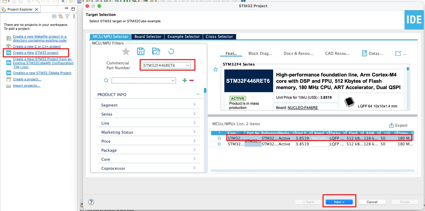
Start CubeMX and create a New Project. Select your board or MCU from the list.
- For this tutorial we use STM32F446RE.
- If you use an STM32F103C8, select it from the MCU list.
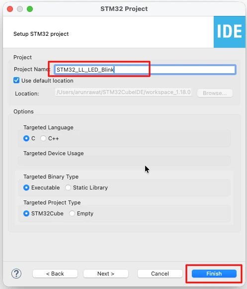
Next, provide some name for this project and click finish.
STM32 Clock Configuration
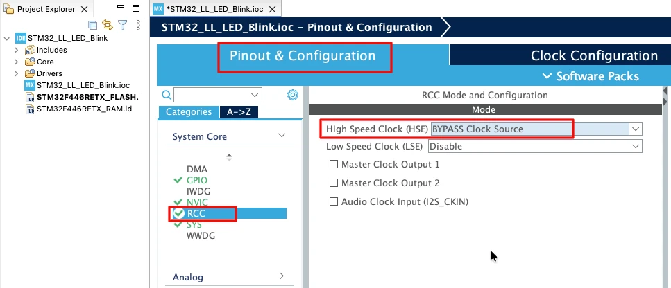
Before generating the project, we must configure the system clock. Open the Clock Configuration tab in CubeMX.
For the STM32F446RE, we will use the 8 MHz external crystal in bypass mode. This is the default clock source on the Nucleo board. The bypass mode uses the clock from the on-board ST-Link MCU.
We will feed this into the PLL and run the system at 180 MHz, which is the maximum frequency for this MCU.
The image below shows the complete PLL and clock configuration used to achieve 180 MHz.
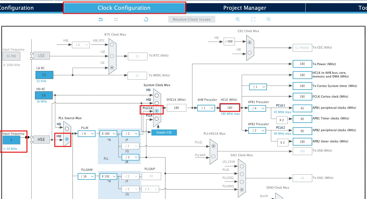
This fast system clock ensures accurate delays and smooth blinking using LL drivers. The SysTick timer will also run from this 180 MHz system clock, which becomes important in the delay functions we will use later.
Note for STM32F103C8:
This MCU uses an 8 MHz external crystal as well, but its maximum frequency is 72 MHz. If you are using the Blue Pill, configure the PLL so that the final system clock is 72 MHz.
GPIO Configuration
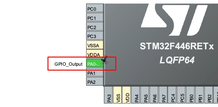
I am going to connect an LED to pin PA0. Hence the pin needs to be configured in the output mode.
The image below shows the GPIO pin configured as output.
Enabling the LL Drivers
Now open Project Manager → Advanced Settings. Enable LL Drivers for all peripherals. This ensures CubeMX generates clean, lightweight LL code.
The image below shows the LL driver selection in CubeMX.
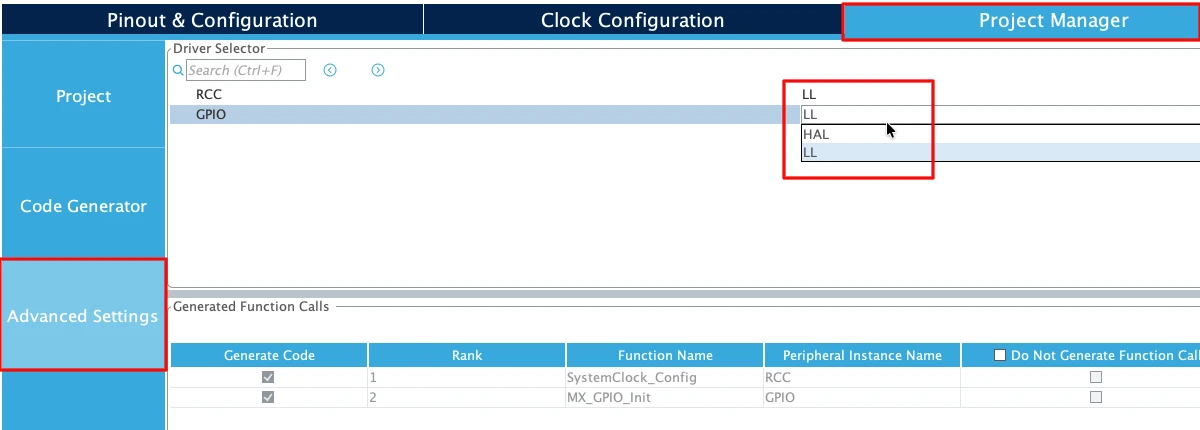
This step is important because CubeMX uses HAL by default. Switching to LL gives you direct control over the GPIO registers.
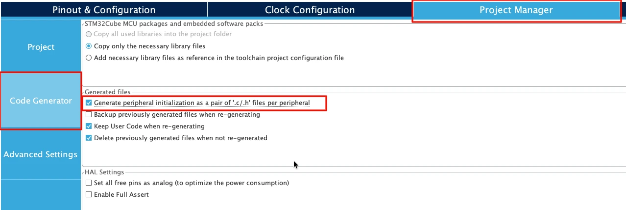
Next, go to Code Generator and select “Generate Peripheral Initialization as a pair of .c/.h files per peripheral”. This will generate a separate source files for all the peripherals we will use in a project.
Generating Code in STM32CubeMX
Click save to generate the project. CubeMX now produces the full LL project structure including:
- main.c
- system clock initialization
- GPIO initialization
- startup files
- linker script
You will find all LL initialization functions inside gpio.c and main.c.
The image below shows the generated project structure inside STM32CubeIDE.
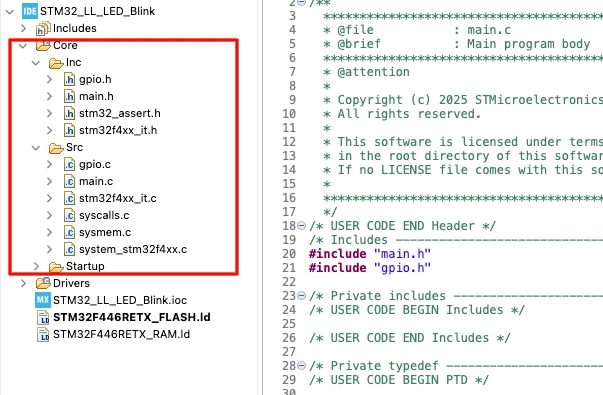
When the code is generated, CubeIDE opens automatically. You can now see functions like:
MX_GPIO_Init()SystemClock_Config()MX_GPIO_Init()
These functions form the base of the LED blink code we will write next.
Understanding the LL Code for Blinking an LED
In this section, we will explore the core LL functions used in the LED blinking code. You will see how GPIO clocks are enabled, how a pin is configured, how SysTick handles delays, and how LL functions control the LED. These concepts form the base of almost every LL-driven STM32 project.
Although we do not need to write these as these functions are generated by CubeMX itself.
GPIO Clock Initialization Explained
Before any GPIO pin can be used, its port must receive a clock.
In LL, this is done using:
LL_AHB1_GRP1_EnableClock(LL_AHB1_GRP1_PERIPH_GPIOA);This line turns ON the clock for GPIOA in the RCC register system.
LL_AHB1_GRP1: AHB1 bus groupEnableClock: Enables the peripheral clockGPIOA: Target GPIO port
Without enabling this clock, the pin will not work.
GPIO Pin Configuration Explained
CubeMX generates a structure and passes it to LL_GPIO_Init():
LL_GPIO_InitTypeDef GPIO_InitStruct = {0};

GPIO_InitStruct.Pin = LL_GPIO_PIN_0;
GPIO_InitStruct.Mode = LL_GPIO_MODE_OUTPUT;
GPIO_InitStruct.Speed = LL_GPIO_SPEED_FREQ_LOW;
GPIO_InitStruct.OutputType = LL_GPIO_OUTPUT_PUSHPULL;
GPIO_InitStruct.Pull = LL_GPIO_PULL_NO;

LL_GPIO_Init(GPIOA, &GPIO_InitStruct);Here is what each field does:
- Pin: Selects which pin will be configured
- Mode: Output mode
- Speed: Maximum speed of signal switching
- OutputType: Push-pull mode
- Pull: No pull-up / pull-down
LL_GPIO_Init() writes these values into GPIO registers. It is generated by CubeMX, so we do not need to write it ourself.
LL_Delay and SysTick
The LED needs a delay to blink. The LL library provides:
LL_mDelay(500);This uses the SysTick timer, which CubeMX configures during system initialization.
For F446:
LL_Init1msTick(180000000);This sets up a 1 ms tick based on a 180 MHz clock.
For F103:
LL_Init1msTick(72000000);This creates the same 1 ms tick from 72 MHz.
LL_mDelay() simply waits until the requested milliseconds have passed.
Toggling the LED Using LL_GPIO_TogglePin
The main blinking action happens using:
LL_GPIO_TogglePin(GPIOA, LL_GPIO_PIN_0);This flips the pin output:
- HIGH -> LOW
- LOW -> HIGH
When used in a loop with a delay, it produces a clean blink.
Changing the LED State with LL_GPIO_SetOutputPin
If you want to turn the LED ON, you can use:
LL_GPIO_SetOutputPin(GPIOA, LL_GPIO_PIN_0);This function writes a HIGH level to the pin. It is useful when you want the LED to start in ON state or need precise control instead of toggling.
Similarly, If you want to turn the LED OFF, you can use:
LL_GPIO_ResetOutputPin(GPIOA, LL_GPIO_PIN_0);Writing to an Entire Port Using LL_GPIO_WriteOutputPort
Sometimes we need to control a specific pin using bitwise operations instead of functions like LL_GPIO_SetOutputPin() or LL_GPIO_ResetOutputPin(). This gives more control and is useful when multiple pins on the same port are used.
Your code looks like this:
uint16_t portA = LL_GPIO_ReadOutputPort(GPIOA);
LL_GPIO_WriteOutputPort(GPIOA, portA | (1 << 0));

LL_GPIO_WriteOutputPort(GPIOA, portA & (~(1 << 0)));Let’s break this down step by step.
1. Reading the Current Output State
uint16_t portA = LL_GPIO_ReadOutputPort(GPIOA);This reads the entire 16-bit output register of GPIOA.
Every bit represents the current logic level of a pin:
- Bit = 1 -> Pin is HIGH
- Bit = 0 -> Pin is LOW
This is important because when writing to the port, we must avoid overwriting other pins.
2. Setting a Pin HIGH Using Bitwise OR
LL_GPIO_WriteOutputPort(GPIOA, portA | (1 << 0));Here:
(1 << 0)produces0x0001, which targets PA0portA | (1 << 0)sets bit 0 to 1- All other bits stay unchanged
So this line turns PA0 ON while keeping the rest of the port untouched. This is similar to using LL_GPIO_SetOutputPin(), but you can now set multiple pins or perform faster operations.
3. Setting a Pin LOW Using Bitwise AND with NOT
LL_GPIO_WriteOutputPort(GPIOA, portA & (~(1 << 0)));Here:
(1 << 0)→ selects PA0~(1 << 0)→ inverts it, creating a mask where only bit 0 becomes 0portA & (mask)→ forces bit 0 to 0, and keeps all other bits as they are
This line turns PA0 OFF. This is equivalent to LL_GPIO_ResetOutputPin(), but done using direct port writing.
When to Use Port Writes Instead of Toggle Functions
Using LL_GPIO_WriteOutputPort() is useful when:
- You want faster GPIO control
- You work with multiple pins simultaneously
- You need atomic read-modify-write operations
- You want full flexibility with bitwise operations
Just remember:
It writes the entire port, So always use LL_GPIO_ReadOutputPort() first, And modify only the bits you need.
This ensures you do not accidentally change other GPIO pins.
Hardware Connections for LED
Before testing the input methods, we need a simple hardware setup. I have connected an LED to PA0.
The image below shows the correct wiring for the LED.
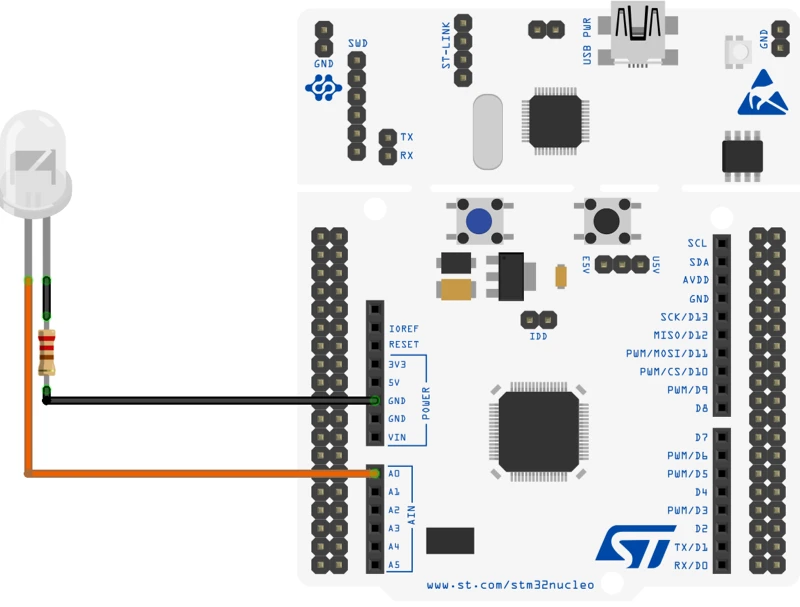
- The LED connected to PA0 turns ON, OFF, or toggles depending on the writing method.
- A resistor is placed in series between PA0 and GND to protect the LED.
Full STM32 LL LED Blink Code
In this section, we will look at the different ways to blink the LED. This will give you a clear idea about controlling a GPIO pin using different available functions in the STM32 LL library.
Control LED Using LL_GPIO_TogglePin
We can use the function LL_GPIO_TogglePin() to toggle the LED pin. This function flips the state of the pin.
Below is the main code for blinking the LED.
int main(void)
{
  /* Reset of all peripherals, Initializes the Flash interface and the Systick. */
  LL_APB2_GRP1_EnableClock(LL_APB2_GRP1_PERIPH_SYSCFG);
  LL_APB1_GRP1_EnableClock(LL_APB1_GRP1_PERIPH_PWR);

  /* System interrupt init*/
  NVIC_SetPriorityGrouping(NVIC_PRIORITYGROUP_4);

  /* SysTick_IRQn interrupt configuration */
  NVIC_SetPriority(SysTick_IRQn, NVIC_EncodePriority(NVIC_GetPriorityGrouping(),15, 0));

  /* Configure the system clock */
  SystemClock_Config();

  MX_GPIO_Init();

  while (1)
  {
	  LL_GPIO_TogglePin(GPIOA, LL_GPIO_PIN_0);
	  LL_mDelay(500);
  }
}The entire main function is generated by the cubeMX. Here we will just write the while loop. Inside this loop, we call the function LL_GPIO_TogglePin() to toggle the state of the pin PA0. If the Pin is set, this code will Reset it, otherwise if the pin is Reset, this code will Set the Pin.
LL_mDelay(500) will provide 500ms delay between each call to the toggle function. This will have an effect of LED connected to PA0, blinking every 500ms.
The gif below shows the output of the code. The LED blinks every 500ms.

Control LED Using LL_GPIO_SetOutputPin
The function LL_GPIO_TogglePin() toggles the state of the pin, but sometimes we do not need the LED to blink at a fixed rate. For example, if I want to turn the LED ON for 500ms and then OFF for 2 seconds, I can not use the toggle function. This is where we need a set of functions to set or reset the pin.
We can use the function LL_GPIO_SetOutputPin to set a particular pin and LL_GPIO_ResetOutputPin to Reset a pin. Below is code showing the usage of these function.
int main()
{
  ....
  ....
    while (1)
    {
	    LL_GPIO_SetOutputPin(GPIOA, LL_GPIO_PIN_0);
	    LL_mDelay(500);
	    LL_GPIO_ResetOutputPin(GPIOA, LL_GPIO_PIN_0);
	    LL_mDelay(2000);
    }
}This code will turn the LED ON for 500ms and OFF for 2 seconds. Since the reset of the main code is pregenerated by the cubeMX, I have not shown it here.
The gif below shows the output of the code.

Control LEDs Using LL_GPIO_WriteOutputPort
We can also control the output pins directly by writing to the Port (PORTA). This is useful when we need to manipulate multiple pins of a port at once. For example, If I want to control pins PA0 and PA1, I can directly write the PORTA.
The code below demonstrates this example.
int main()
{
  ....
  ....
  while (1)
  {
	  uint16_t portA = LL_GPIO_ReadOutputPort(GPIOA);
	  LL_GPIO_WriteOutputPort(GPIOA, portA|0x03);
	  LL_mDelay(500);
	  LL_GPIO_WriteOutputPort(GPIOA, portA&(~(0x03)));
	  LL_mDelay(500);
  }
}It is always good practice to read the current port value before modifying it. This ensures that when we write back to the port, we do not accidentally overwrite the state of other pins configured on the same GPIO port.
To set PA0 and PA1, we perform an OR operation with the value read from the port:
portA | 0x03
This keeps all existing bits unchanged while setting only PA0 and PA1 to logic HIGH.
To reset the same pins, we apply an AND operation with the inverted bit mask:
portA & (~0x03)
This clears PA0 and PA1 while preserving the state of all other pins on GPIOA.
This read-modify-write approach guarantees safe control of individual pins without disturbing the rest of the port.
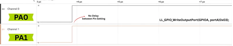
The images below shows the advantage of using the Port function while controlling multiple pins.
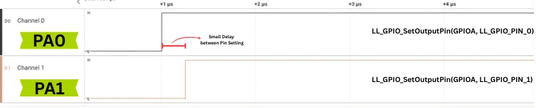
When using LL_GPIO_SetOutputPin for PA0 and PA1, each pin is updated separately. This causes a small, visible delay between PA0 going high and PA1 following it.
However, when using LL_GPIO_WriteOutputPort, the port is updated in a single write operation. As a result, PA0 and PA1 go high at exactly the same moment.
Conclusion
In this tutorial, we learned how to get started with STM32 development using the LL (Low-Layer) drivers. A basic STM32CubeMX project was created, the system clock was configured, GPIO clocks were enabled, and the output pins were initialized. The tutorial also explained how SysTick works with LL_Delay and examined key LL GPIO functions such as LL_GPIO_TogglePin, LL_GPIO_SetOutputPin, and LL_GPIO_WriteOutputPort.
Two methods of controlling multiple pins were compared, using individual pin set functions versus performing a full port write, and their behavior was demonstrated using logic analyzer captures. This blink example forms the foundation of your LL programming journey. In the next tutorials of this series, we will build on this knowledge and explore more advanced STM32 peripherals using the LL approach.
Browse More STM32 LL Tutorials

STM32 UART using LL Drivers (Part 1): Transmit using Polling Mode

STM32 UART using LL Drivers (Part 2): Transmit using Interrupt & DMA
STM32 UART using LL Drivers (Part 3): Receive Data in Blocking Mode

STM32 UART using LL Drivers (Part 4): Receive Data in Interrupt Mode

STM32 UART using LL Drivers (Part 5): Receive Using DMA (Normal and Circular Mode)
STM32 ADC Using LL Drivers (Part 1): Single Channel Blocking and Interrupt Mode

STM32 ADC Using LL Drivers (Part 2): Multiple Channels using DMA Mode
STM32 LL Project Download
STM32 LL LED Control FAQs
Subscribe
Login
0 Comments
Newest
