Published: February 1, 2026
Last Updated: February 15, 2026
Last Updated: February 15, 2026
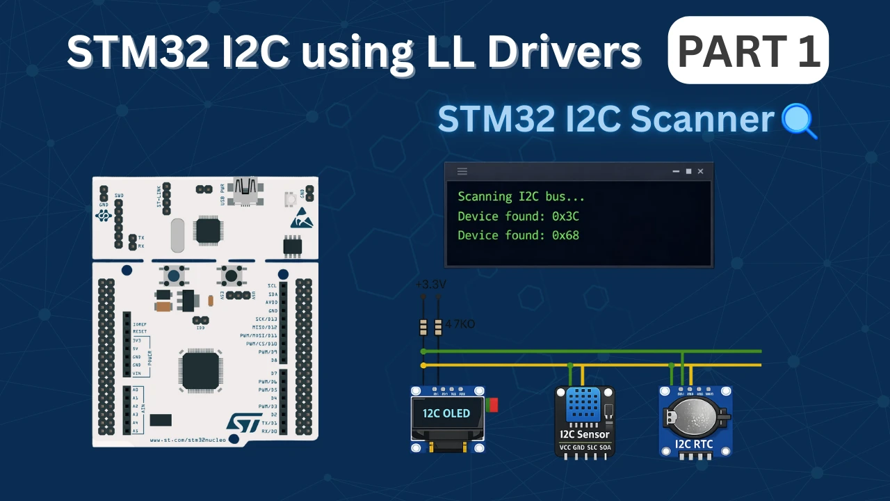
STM32 I2C Scanner Tutorial Using Low-Layer (LL) Drivers
I2C is one of the most common communication protocols in embedded systems. Sensors, displays, RTCs, and memory modules often communicate over I2C. When working with these devices, the first step is always to confirm they are properly connected and responding on the bus. An I2C scanner solves this problem. It searches through all possible I2C addresses and reports which devices are active. This makes it an essential debugging tool before starting any I2C project.
In this tutorial, we will build an I2C scanner using STM32 Low-Layer (LL) drivers. The focus stays on the basics. We will use STM32CubeMX to handle the clock and peripheral setup, so there is no need to write initialization code manually. The scanner itself requires just a few LL functions, making it simple to understand and easy to use.
This tutorial works on any STM32 board. The examples here use the STM32F446RE Nucleo and the STM32F103C8 Blue Pill, but the code remains the same across different STM32 families. The I2C scanner will transmit results over UART, so we will also implement printf redirection to make the output clean and readable.
What is an I2C Scanner and Why Do You Need One?
An I2C scanner is a simple program that checks every possible I2C address on the bus and reports which devices respond. Think of it as a network scanner for your microcontroller. It sends a request to each address and waits for an acknowledgment. If a device is present, it responds with an ACK signal. If nothing is connected at that address, the scanner receives a NACK and moves to the next one.
This tool becomes essential when working with multiple I2C modules or when debugging communication issues. Instead of blindly trying to read from a sensor, the scanner confirms the device is physically present and responding. This saves time and removes guesswork from the debugging process.
Understanding I2C Device Addresses
I2C uses 7-bit addressing, which means there are 128 possible addresses (0x00 to 0x7F). However, not all addresses are usable. The I2C specification reserves some addresses for special purposes:
- 0x00 to 0x07 – Reserved addresses
- 0x78 to 0x7F – Reserved addresses
This leaves 0x08 to 0x77 as valid device addresses. Most I2C modules fall within this range.
Many I2C devices have a fixed address set by the manufacturer. For example:
- SSD1306 OLED Display – Usually 0x3C or 0x3D
- DS3231 RTC Module – Fixed at 0x68
- MPU6050 IMU Sensor – 0x68 or 0x69 (selectable via AD0 pin)
- BME280 Sensor – 0x76 or 0x77 (depends on SDO pin)
Some modules allow address selection through hardware pins (like A0, A1, A2 on the PCF8574). This lets you connect multiple devices of the same type on a single I2C bus. Knowing the exact address of your device is critical before writing any communication code, and the I2C scanner reveals this immediately.
STM32CubeMX Configuration for I2C Scanner
We will use STM32CubeMX for the the initial setup. We only need to configure the I2C peripheral for scanning and USART for displaying the results. The clock setup and GPIO configuration are handled by CubeMX, so we can focus on writing the scanner logic instead of dealing with register-level details.
This section walks through creating a new project, enabling I2C1, setting up USART2 for output, and generating the final code.
STM32 Clock Configuration
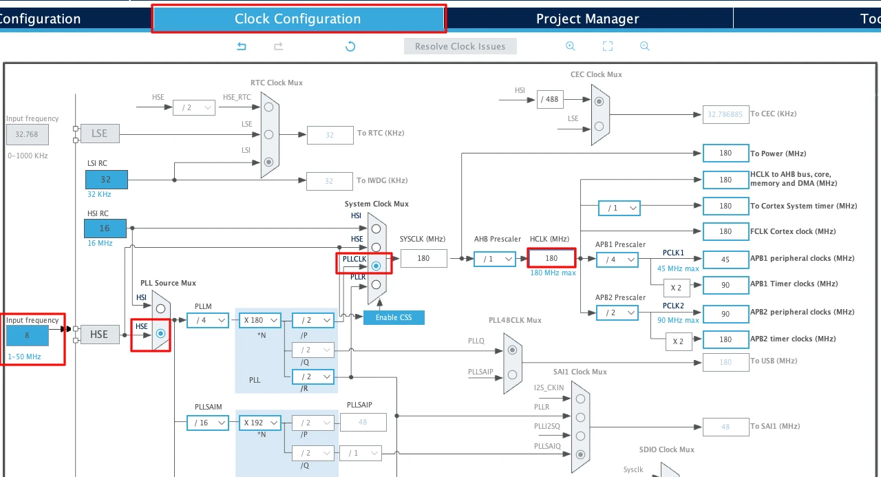
Before generating the project, we must configure the system clock. Open the Clock Configuration tab in CubeMX.
For the STM32F446RE, we will use the 8 MHz external crystal in bypass mode. This is the default clock source on the Nucleo board. The bypass mode uses the clock from the on-board ST-Link MCU.
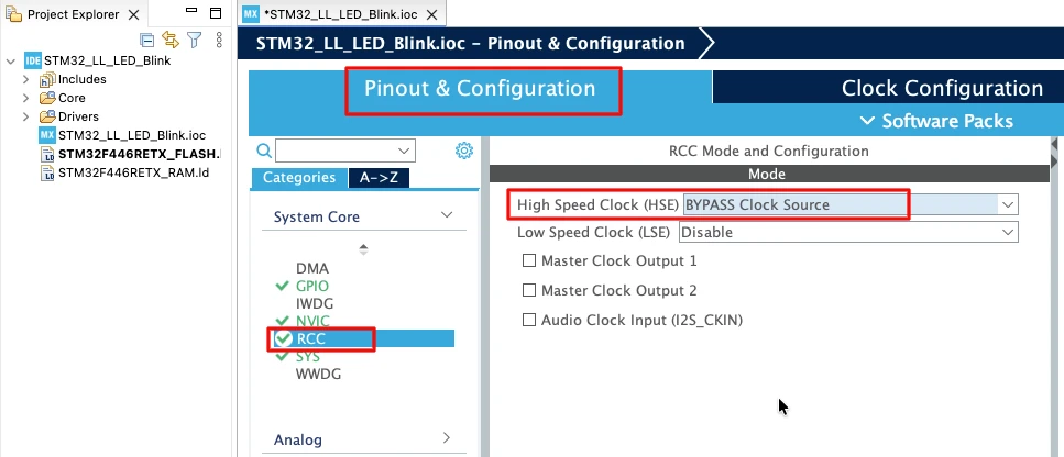
We will feed this into the PLL and run the system at 180 MHz, which is the maximum frequency for this MCU.
The image below shows the complete PLL and clock configuration used to achieve 180 MHz.
This fast system clock ensures accurate delays and smooth blinking using LL drivers. The SysTick timer will also run from this 180 MHz system clock, which becomes important in the delay functions we will use later.
Note for STM32F103C8
This MCU uses an 8 MHz external crystal as well, but its maximum frequency is 72 MHz. If you are using the Blue Pill, configure the PLL so that the final system clock is 72 MHz.
Configuring I2C1 Peripheral
I am going to use the I2C1 peripheral. Configure it in Standard Mode (100kHz), which is the most common I2C speed and works reliably with all devices.
The image below shows the I2C1 configuration in STM32CubeMX.
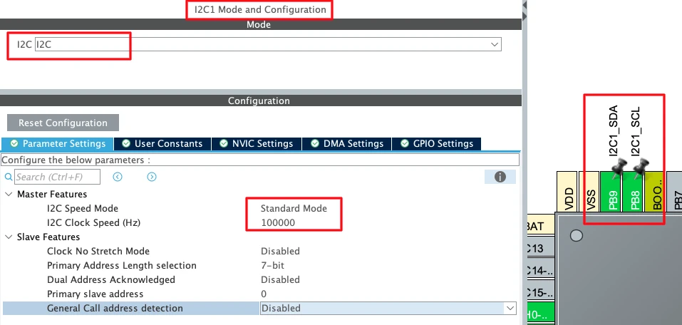
CubeMX automatically assigns the default I2C1 pins:
- PB6 → SCL (Clock Line)
- PB7 → SDA (Data Line)
These pins are standard for I2C1 on most STM32 boards. I have manually changes the pins to PB8 and PB9. These pins are easier to access on the nucleo boards.
Now configure the I2C parameters. Click on the Configuration tab under I2C1.
Set the following values:
- I2C Speed Mode: Standard Mode
- I2C Clock Speed: 100000 Hz (100 kHz)
Leave the rest of the settings at their default values.
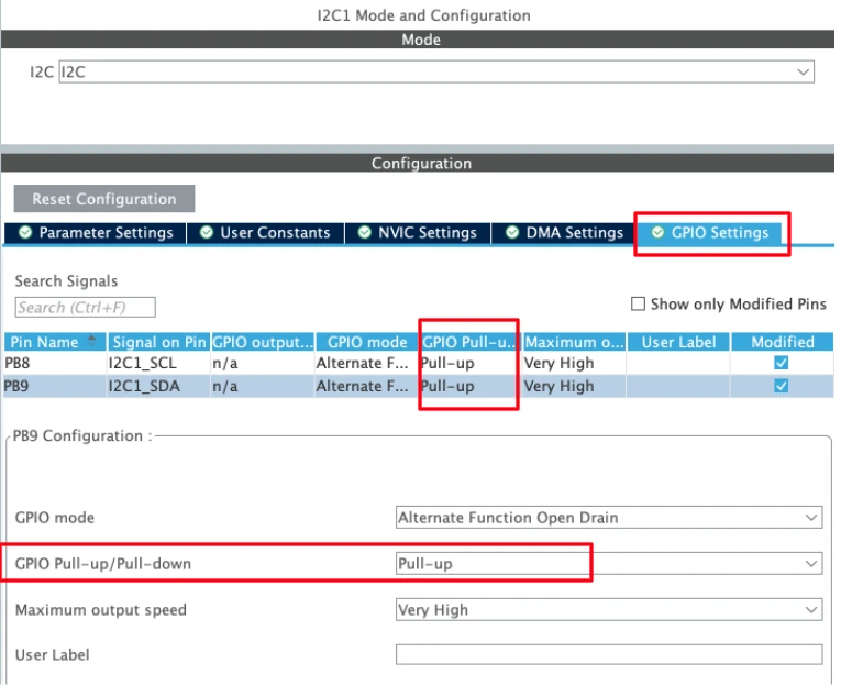
STM32 microcontrollers support internal pull-up resistors on the I²C SCL and SDA lines. Enabling these pull-ups helps ensure proper bus idle levels when no external pull-up resistors or I²C devices are connected.
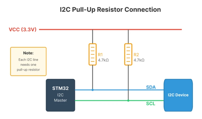
If the device is not detected even after enabling the internal pull-up resistors, you might need to connect external pull ups as shown in the image below.
UART Configuration
I am going to use UART to print the ADC result on the serial console. I have already covered a tutorial explaining how to configure and use UART peripheral of the STM32 with LL drivers. The image below shows the UART configuration.
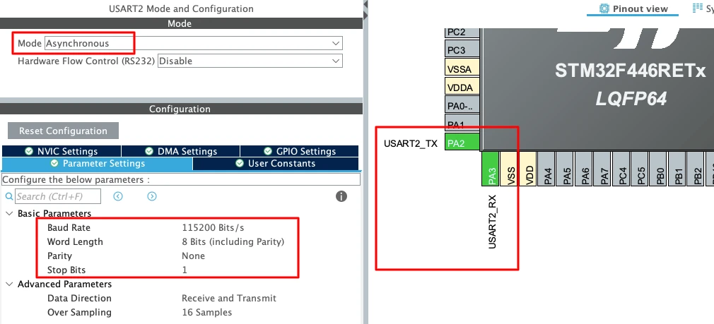
To enable USART2 in CubeMX:
- Set the Mode to Asynchronous.
- CubeMX automatically assigns the correct pins:
- PA2 -> TX
- PA3 -> RX
- Keep the Baud Rate to a common value like 115200.
Enabling the LL Drivers
Before generating the code, we need to enable LL drivers instead of HAL. This ensures CubeMX generates lightweight LL functions for I2C and USART.
Open Project Manager → Advanced Settings. Enable LL Drivers for all peripherals. This ensures CubeMX generates clean, lightweight LL code.
The image below shows the LL driver selection in CubeMX.
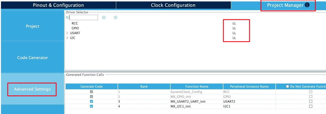
This step is critical. Without enabling LL drivers, CubeMX generates HAL code, which is heavier and not compatible with the LL functions.
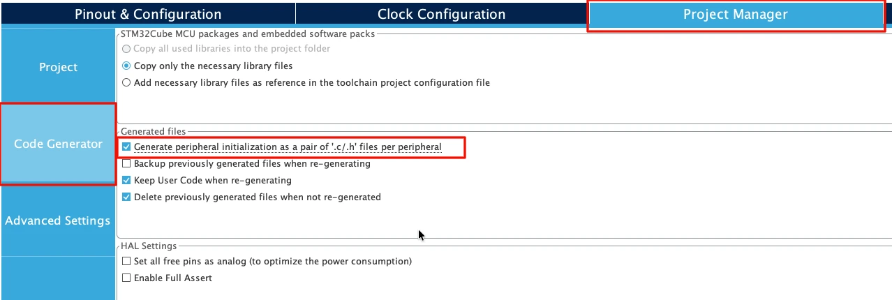
Next, go to Code Generator and select “Generate Peripheral Initialization as a pair of .c/.h files per peripheral”. This will generate a separate source files for all the peripherals we will use in a project.
Understanding I2C Communication Basics
Before writing the scanner code, it helps to understand how I2C communication works at a basic level. I2C is a simple two-wire protocol that connects multiple devices on the same bus. The master device (STM32) controls the communication, while slave devices (sensors, displays, etc.) respond when addressed.
This section explains the core concepts needed to understand how the scanner detects devices.
How I2C Protocol Works
I2C uses only two wires for communication:
- SDA (Serial Data) – Carries the actual data
- SCL (Serial Clock) – Provides the timing signal
The master generates the clock signal and initiates all communication. Slave devices listen on the bus and respond only when their address is called.
Master-Slave Communication:
In an I2C system, one device acts as the master and controls the bus. All other devices are slaves. The master decides when to start communication, which slave to talk to, and when to stop.
For our scanner:
- STM32 = Master (controls the bus)
- Sensors, displays, etc. = Slaves (respond when addressed)
7-Bit Addressing:
Each I2C device has a unique 7-bit address. When the master wants to communicate with a device, it sends that address on the bus. The device at that address responds, while all other devices ignore the message.
The address is sent as the first byte after the START condition. The 8th bit of this byte indicates whether the master wants to read or write:
- Bit 0 = 0 → Write operation
- Bit 0 = 1 → Read operation
For scanning, we always use write mode because we only need to check if a device responds.
I2C START and STOP Conditions
I2C communication begins with a START condition and ends with a STOP condition. These are special signal patterns that tell all devices on the bus when a transaction begins and ends.
START Condition:
The START condition happens when the master pulls SDA LOW while SCL is HIGH. This alerts all slave devices that communication is about to begin.
In LL drivers, we generate a START condition using:
LL_I2C_GenerateStartCondition(I2C1);After sending START, the master must wait for the hardware to complete the operation. We check the SB (Start Bit) flag:
while(!LL_I2C_IsActiveFlag_SB(I2C1));Once this flag is set, the START condition is complete and the bus is ready for the next step.
STOP Condition:
The STOP condition happens when the master releases SDA to HIGH while SCL is already HIGH. This signals the end of the communication.
In LL drivers, we generate a STOP condition using:
LL_I2C_GenerateStopCondition(I2C1);The STOP condition frees the bus so another transaction can begin. For the scanner, we send STOP after checking each address, whether a device responded or not.
Why START and STOP Matter:
Every I2C transaction must begin with START and end with STOP. If you forget the STOP condition, the bus stays busy and the next transaction will fail.
ACK and NACK Response
After the master sends an address, the slave device must respond with either an ACK (Acknowledge) or NACK (Not Acknowledge) signal. This tells the master whether the device is present and ready to communicate.
ACK (Acknowledge):
If a device at the sent address exists on the bus, it pulls SDA LOW during the 9th clock pulse. This is called an ACK signal.
The master detects this by checking the ADDR (Address Sent) flag:
LL_I2C_IsActiveFlag_ADDR(I2C1)If this flag is set, it means a device responded at that address. ACK = Device found
NACK (Not Acknowledge):
If no device exists at the sent address, SDA stays HIGH during the 9th clock pulse. This is called a NACK signal.
The master detects this by checking the AF (Acknowledge Failure) flag:
LL_I2C_IsActiveFlag_AF(I2C1)If this flag is set, it means no device responded. NACK = No device at this address
How the Scanner Uses ACK and NACK:
The scanner sends a START condition, transmits an address, and then checks which flag gets set:
- If ADDR flag is set → Device found, print the address
- If AF flag is set → No device, move to the next address
This simple check is the core logic of the I2C scanner. By looping through all addresses (0x08 to 0x77) and checking for ACK or NACK, the scanner builds a complete list of active devices on the bus.
After checking the flags, the scanner must clear them before moving to the next address:
LL_I2C_ClearFlag_ADDR(I2C1);  // Clear ADDR flag if device found
LL_I2C_ClearFlag_AF(I2C1); // Clear AF flag if no deviceThis ensures the hardware is ready for the next scan cycle.
Writing I2C Scanner Code with LL Drivers
Now that the hardware and CubeMX configuration are ready, we can write the actual scanner code. The I2C scanner uses only a few LL functions to check each address and report which devices respond. We will also set up printf redirection so the results display cleanly on the serial terminal.
This section shows how to build the scanner step by step.
Setting Up Printf Redirection
Using printf() makes debugging much easier. Instead of manually sending each character over UART, we redirect all printf output to USART2. This works by overriding the low-level _write() function that printf calls internally.
Add this function anywhere in your main.c file, outside of the main function:
int __io_putchar(int ch)
{
    while (!LL_USART_IsActiveFlag_TXE(USART2));
    LL_USART_TransmitData8(USART2, (char)ch);
    return ch;
}This simple function waits for the UART transmit buffer to become empty, then sends one character. The printf() function calls this repeatedly to send entire strings.
Creating the I2C Scanner Function
The scanner function loops through all valid I2C addresses (0x08 to 0x77), sends a START condition, transmits the address, and checks if a device responds. If the ADDR flag is set, a device is present. If the AF flag is set, no device exists at that address.
Here is the complete scanner function:
void I2C_Scanner(void)
{
    printf("Scanning I2C bus...\r\n\r\n");

    uint8_t devices_found = 0;

    // Scan from address 0x08 to 0x77 (valid 7-bit I2C address range)
    for(uint8_t address = 0x08; address < 0x78; address++)
    {
        // Generate START condition
        LL_I2C_GenerateStartCondition(I2C1);

        // Wait for START condition to be generated
        while(!LL_I2C_IsActiveFlag_SB(I2C1));

        // Send address with WRITE bit (LSB = 0)
        LL_I2C_TransmitData8(I2C1, (address << 1) | 0x00);

        // Wait for address to be sent
        while(!LL_I2C_IsActiveFlag_ADDR(I2C1) && !LL_I2C_IsActiveFlag_AF(I2C1));

        // Check if ACK received (device found)
        if(LL_I2C_IsActiveFlag_ADDR(I2C1))
        {
            // Device responded
            printf("Device found at address: 0x%02X\r\n", address);
            devices_found++;
        }

        // Clear ADDR flag
        LL_I2C_ClearFlag_ADDR(I2C1);

        // Clear AF flag if no device
        LL_I2C_ClearFlag_AF(I2C1);

        // Generate STOP condition
        LL_I2C_GenerateStopCondition(I2C1);

        // Small delay between scans
        LL_mDelay(2);
    }

    printf("*****Scan Complete*****\r\n");
    printf("Total devices found: %d\r\n\r\n", devices_found);
}Explanation of Each Step:
1. Generate START Condition:
LL_I2C_GenerateStartCondition(I2C1);
while(!LL_I2C_IsActiveFlag_SB(I2C1));This creates the START condition and waits for the hardware to confirm it. The SB flag indicates the START bit was sent successfully.
2. Send Address:
LL_I2C_TransmitData8(I2C1, (address << 1) | 0x00);The I2C address is 7 bits, but we send 8 bits total. The address is shifted left by 1 bit, and the LSB is set to 0 to indicate a write operation. Even though we are not actually writing data, the I2C protocol requires us to specify read or write mode.
3. Wait for Response:
while(!LL_I2C_IsActiveFlag_ADDR(I2C1) && !LL_I2C_IsActiveFlag_AF(I2C1));This waits until either the ADDR flag (device responded) or the AF flag (no device) is set. We cannot proceed until one of these flags becomes active.
4. Check Which Flag Was Set:
if(LL_I2C_IsActiveFlag_ADDR(I2C1))
{
    printf("Device found at address: 0x%02X\r\n", address);
    devices_found++;
}If the ADDR flag is set, a device is present at this address. We print the address in hexadecimal format and increment the device counter.
5. Clear Flags and Send STOP:
LL_I2C_ClearFlag_ADDR(I2C1);
LL_I2C_ClearFlag_AF(I2C1);
LL_I2C_GenerateStopCondition(I2C1);We must clear the ADDR flag and AF flag before moving to the next address. The STOP condition ends the transaction and frees the bus.
6. Add Delay:
LL_mDelay(2);A small delay between scans ensures the bus has time to settle. Without this, some devices might not respond correctly.
The main function
Now we combine everything into the main function.
int main(void)
{
  ......
  // PreGenerated Functions
  ......

  /* USER CODE BEGIN 2 */
  printf("***** STM32 I2C Scanner using LL Drivers *****\r\n");

  I2C_Scanner();
  /* USER CODE END 2 */
  while (1)
  {

  }
}This code runs the scanner once at startup and prints the results to the serial terminal. If you want the scanner to run repeatedly, add the I2C_Scanner() call inside the while loop with a delay:
while (1)
{
    LL_mDelay(5000);  // Wait 5 seconds
    I2C_Scanner();    // Run scanner again
}This makes the scanner check the bus every 5 seconds, which is useful if you are connecting and disconnecting devices during testing.
Testing the I2C Scanner with Real Modules
Now that the code is ready, we can test the scanner with real I2C devices. This section shows what the output looks like with no devices connected, with a single device, and with multiple devices on the same bus.
Testing confirms that the scanner works correctly and helps you learn what different I2C modules look like when detected.
Scanner Output Without Devices
The first test runs the scanner with nothing connected to the I2C bus. This confirms the code compiles and runs without errors, even when no devices are present.
The image below shows the scanner output when no devices are connected.
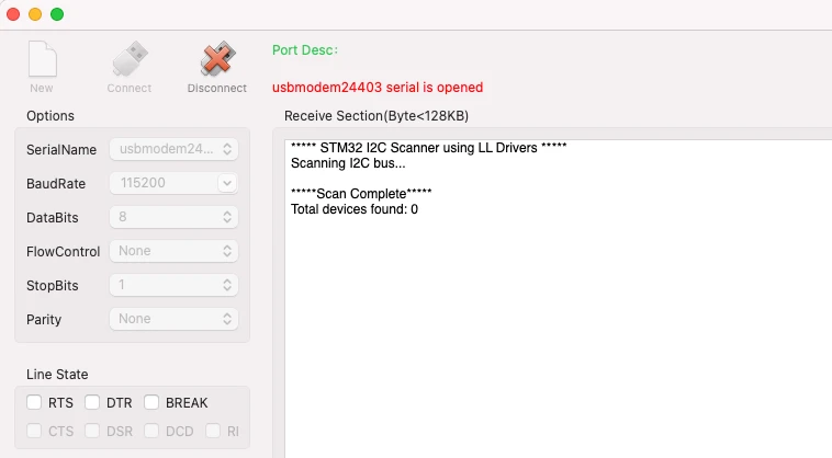
This confirms the scanner is working. The loop checked all addresses from 0x08 to 0x77, but no devices responded, so the total count is zero.
If you see this output, the UART and I2C peripherals are initialized correctly. Now we can connect real devices.
Testing with SSD1306 OLED Display
The SSD1306 OLED display is one of the most common I2C devices. Most modules use address 0x3C by default, though some variants use 0x3D.
Connect the OLED display to your STM32:
- VCC → 3.3V
- GND → GND
- SCL → PB8 (I2C1 clock)
- SDA → PB9 (I2C1 data)
Make sure the connections are secure. If your OLED module does not have built-in pull-up resistors, add 4.7kΩ resistors between SDA/SCL and VCC.
Reset the STM32 or press the reset button. The scanner runs again and this time detects the OLED display.
The image below shows the scanner output with the SSD1306 connected.

The scanner found one device at 0x3C, which matches the SSD1306 OLED display. This confirms the I2C bus is working correctly and the display is responding.
If your display uses address 0x3D, that address will appear instead. Some OLED modules have a solder jumper or resistor that lets you change between 0x3C and 0x3D.
Testing with MPU6050 IMU Sensor
The MPU6050 is a popular 6-axis accelerometer and gyroscope module. It has two possible addresses: 0x68 (default) or 0x69 (if the AD0 pin is connected to VCC).
Connect the MPU6050 as mentioned below:
- VCC → 3.3V
- GND → GND
- SCL → PB8
- SDA → PB9
- AD0 → GND (for address 0x68)
Reset the board and check the serial terminal.
The image below shows the scanner output with the MPU6050 connected.
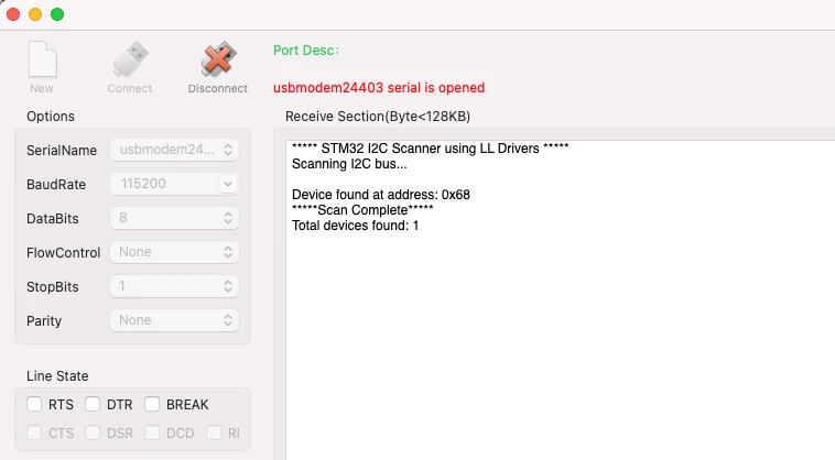
The scanner detected the MPU6050 at 0x68. This is the default address when AD0 is connected to GND.
If you connect AD0 to VCC instead, the address changes to 0x69. You can test this by moving the wire and running the scanner again. This shows how some I2C devices allow address selection through hardware pins.
Testing Multiple I2C Devices
One of the most useful features of I2C is that multiple devices can share the same bus. As long as each device has a unique address, they can all coexist without conflicts.
Connect all the devices, SSD1306 OLED (0x3C), PCF8574 (0x27) and the MPU6050 sensor (0x68) to the same I2C bus:
- All VCC pins → 3.3V
- All GND pins → GND
- All SCL pins → PB8
- All SDA pins → PB9
All devices share the same two wires (SDA and SCL). Reset the board and check the output.
The image below shows the scanner detecting both devices.
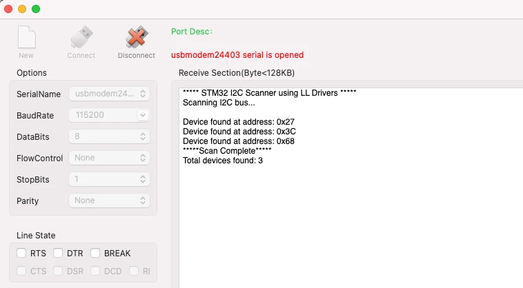
The scanner found all three devices: one at 0x27 (PCF8574), another one at 0x3C (OLED) and third one at 0x68 (MPU6050). All devices are active and ready to communicate.
This demonstrates how the I2C bus handles multiple devices. You can add even more modules as long as their addresses do not conflict. If you try to connect two devices with the same address, only one will respond reliably and communication will fail.
Testing Address Conflicts:
To see what happens during an address conflict, connect both the MPU6050 (0x68) and a DS3231 RTC module (also 0x68) at the same time. The scanner will still show address 0x68, but actual communication with either device will be unstable because both are trying to respond simultaneously. This is why address management matters in multi-device I2C systems.
Conclusion
In this tutorial, we built a fully functional I2C scanner using STM32 Low-Layer (LL) drivers. We started by understanding what an I2C scanner is and why it is essential for debugging I2C communication. The hardware setup was explained in detail, including the role of pull-up resistors and how to connect I2C modules to the STM32. We configured the project in STM32CubeMX by enabling I2C1 and USART2, selected LL drivers for lightweight code, and generated the initialization functions. The tutorial also covered the basics of I2C protocol, including START and STOP conditions, ACK and NACK responses, and how devices communicate on the bus. Finally, we wrote the scanner code, tested it with real modules like the SSD1306 OLED and MPU6050 sensor, and troubleshooted common I2C issues.
This I2C scanner now becomes a permanent tool in your STM32 workflow. Every time you start a new I2C project or connect a new module, running the scanner first confirms the device is present and responding at the correct address. This saves hours of debugging and removes the guesswork from hardware connections. In the next tutorial of this series, we will move beyond scanning and learn how to transmit data to I2C devices using STM32 in master mode. We will write to an EEPROM module, control an I/O expander, and understand how the I2C write operation works at the register level using LL drivers.
Browse More STM32 LL Tutorials
STM32 UART using LL Drivers (Part 4): Receive Data in Interrupt Mode
STM32 UART using LL Drivers (Part 5): Receive Using DMA (Normal and Circular Mode)
STM32 ADC Using LL Drivers (Part 1): Single Channel Blocking and Interrupt Mode
STM32 ADC Using LL Drivers (Part 2): Multiple Channels using DMA Mode
STM32 I2C Using LL Drivers (Part 2): Write Data to EEPROM and I/O Expander
STM32 I2C Using LL Drivers (Part 3): Read Sensor Data from MPU6050
STM32 LL I2C Project Download
STM32 LL I2C FAQs
Subscribe
Login
0 Comments
Newest
