
Home ▸ STM32 Tutorials ▸
Published: April 12, 2025
Last Updated: February 6, 2026
Last Updated: February 6, 2026
Create WebServer on STM32 using Mongoose
In this tutorial you will learn how to build a web server on STM32 using the Mongoose library, how to serve web pages, handle HTTP requests, and expand Ethernet functionality. The project download is available at the end of the post.
Recommended Resources:
This tutorial is a part of the STM32 Ethernet tutorial series. This is also the 2nd tutorial in the mini series covering the implementation of the Mongoose Networking Library. The Previous tutorial in this mini series covered how to set up the Mongoose library on STM32 and get your first project running.
You should take a look at the following tutorials before continuing here:
VIDEO TUTORIAL
You can check the video to see the complete explanation and working of this project.
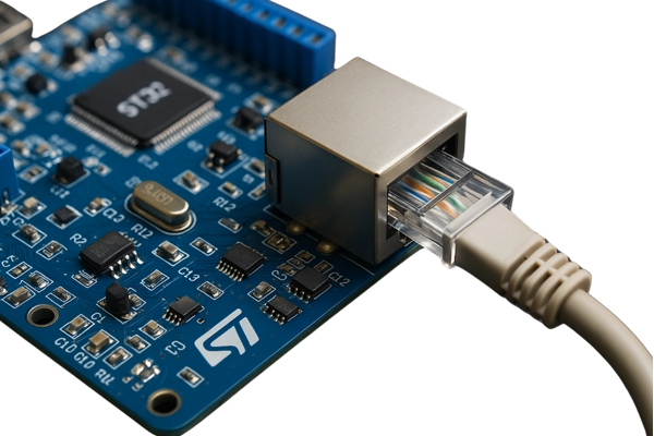
Introducing STM32 Ethernet Peripheral
STM32 microcontrollers with built-in Ethernet MAC (Media Access Controller) enable high-speed wired communication, making them ideal for IoT, industrial automation, and real-time data transfer applications. By integrating Ethernet directly into the MCU, STM32 devices reduce the need for external network controllers, simplifying hardware design and reducing cost.
Below are some important features of STM32 Ethernet:
- Integrated Ethernet MAC: Many STM32 MCUs (like STM32F7 and STM32H7 series) come with a built-in Ethernet MAC controller.
- 10/100 Mbps Support: Compatible with both 10 Mbps and 100 Mbps Ethernet networks.
- RMII/MII Interface: Supports Reduced Media Independent Interface (RMII) and Media Independent Interface (MII) for PHY connection.
- TCP/IP Stack Support: Can work with lightweight stacks like LwIP or full-featured libraries like Mongoose.
- Real-Time Communication: Suitable for deterministic data transfer in real-time applications.
- Low Power Consumption: Optimized for embedded systems with power-saving modes.
Introducing Mongoose Networking Library
Mongoose is a lightweight, embeddable networking library designed for real-time, embedded, and IoT applications. It provides an easy way to implement networking features such as TCP/IP, HTTP, WebSocket, MQTT, and more, making it a powerful tool for creating connected devices.
Below are some important features of the Mongoose:
- Embedded Web Server: Serve web pages and REST APIs directly from your device.
- Built-in Protocols: Supports HTTP, WebSocket, MQTT, and more.
- TLS/SSL Support: Secure communication using mbedTLS or OpenSSL.
- Lightweight & Portable: Minimal footprint, runs on STM32, ESP32, and many platforms.
CREATE WEB UI
We will first create the Web UI, which will then run on our STM32 Dev Board.
Create the Project
We will start with the mongoose wizard to create a new web UI for our test application.
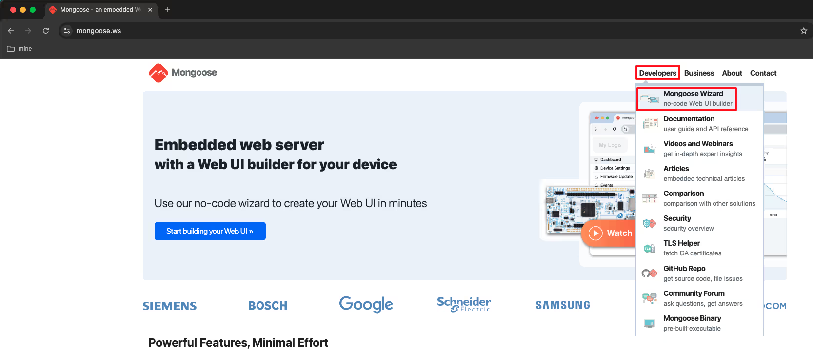
Step 1
Go to the https://mongoose.ws/ and open the Mongoose Wizard.
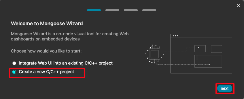
Step 2
If you already have a skeleton project for the dev board, you can integrate the webUI on the existing project. Here I am creating a new project.
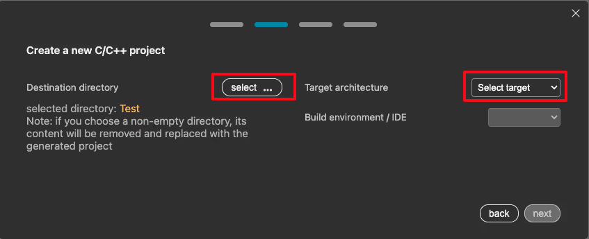
Step 3
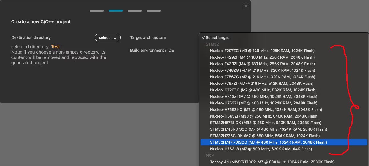
Select the Destination directory, where the new project will be saved. Next we will select the Target Architecture.
Step 4
Mongoose supports various STM32F and STM32H series dev boards. You can choose the target board from the dropdown. I am using the STM32H745 Discover board, hence I ave selected it.
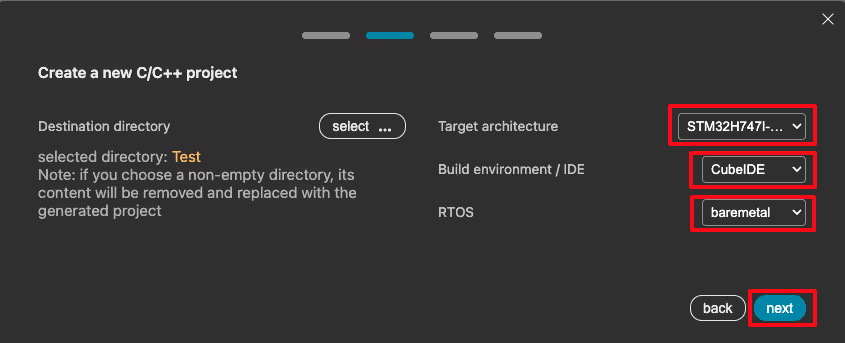
Step 5
Choose the Build Environment / IDE (I am choosing STM32Cube IDE) and the RTOS (I am choose NO RTOS).
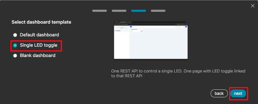
Step 6
Select the Dashboard you want to start with. I am selecting the one with single LED, so that I have something to start with.
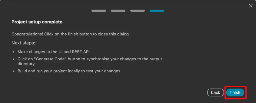
Step 7
Click Finish to go to the web UI page.
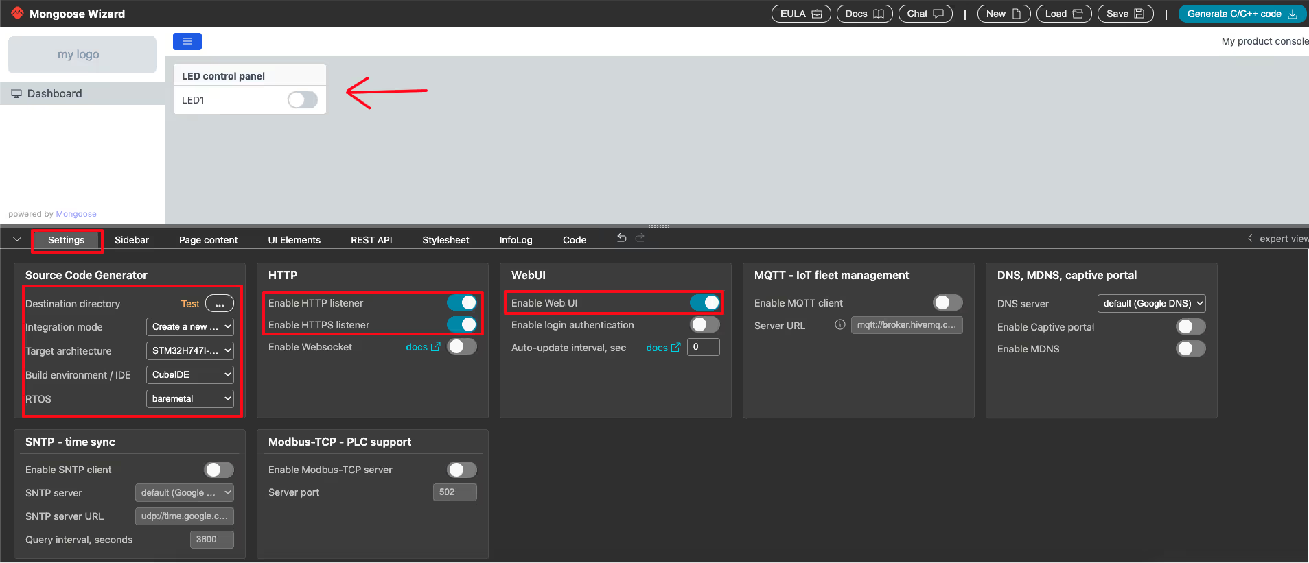
Below is the image showing the default UI with single LED toggle. By default the HTTP and HTTPS listeners are enabled. Also verify the information under Source Code Generator with the configuration we made for the UI.
Edit the Web UI
Now we will add some elements to the UI, which we will later connect with the different components on the STM32 dev board. Below is the image showing the available elements on the mongoose Wizard.
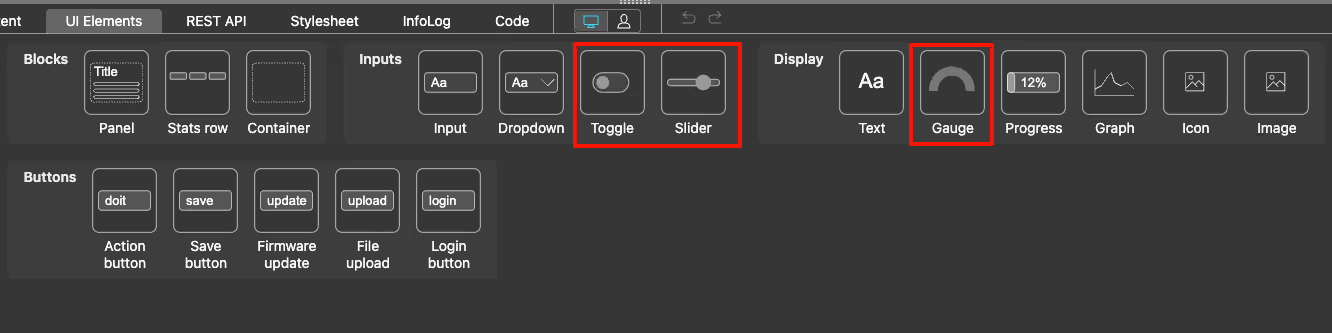
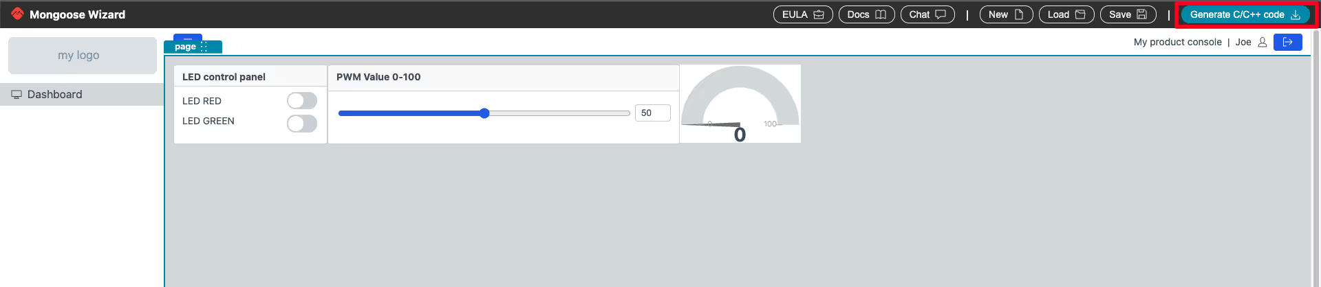
I am going to add one more toggle button for second LED on board, one slider to control the PWM value and one Gauge to display the ADC value on the UI. You can watch the video at the end of the post to understand how to add the elements. Here I will only cover important details about these elements. Below is the image showing the final UI.
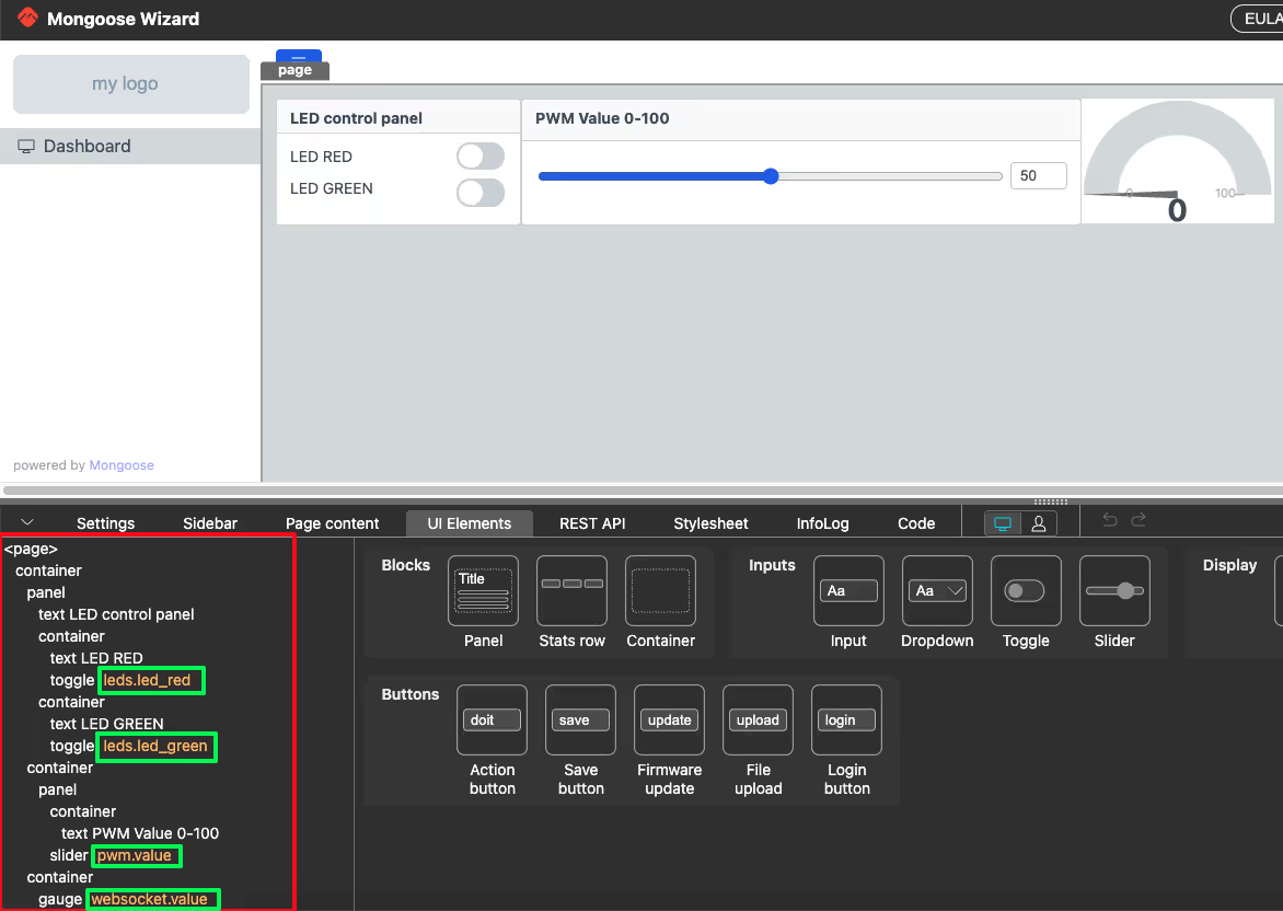
The Red Box shows all the elements used in the UI in their hierarchical order. The Green boxes shows the API handlers for the respective elements. These API variables are actually defined in the REST API tab and they help us integrate these elements with the hardware components. Let’s understand how to define these API variables.
LED Toggle Element
Below is the image showing the configuration for the Toggle button of the LED element.
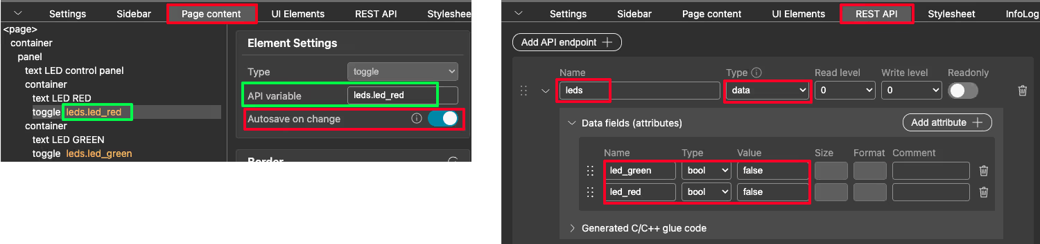
In the REST API tab, we will create an API Endpoint. I named it leds and it is a data type endpoint. The DATA endpoint maps a web UI panel to a C structure.
led_red and led_green are the elements of this structure. Both are boolean type variables with default value being set to false.
On the page element section, set the API variable of the toggle button to the respective endpoint. This way, each time the toggle button is triggered, the current state of the button will be stored into the endpoint. Also make sure to enable the Autosave on change. This will eliminate the need of having a submit button and the change is immediately submitted.
Slider Element
Below is the image showing the configuration for the Slider Element.
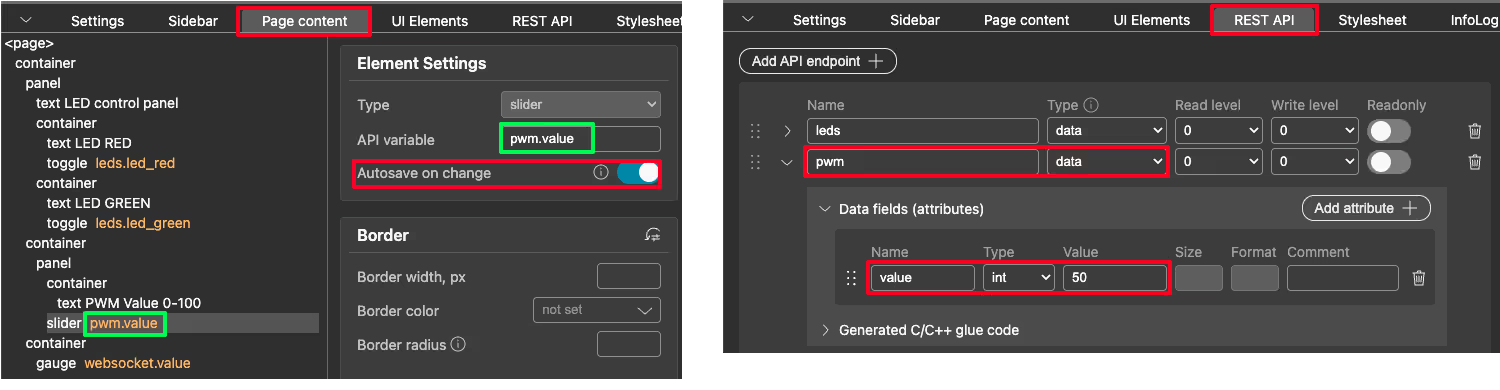
In the REST API section, I have created another API endpoint for the Slider and named it pwm. It is also of the type data, so basically a structure in C. value is the element of this structure. It is an integer type variable and the default value for this variable is set to 50.
On the page element section, set the API variable of the slider to the pwm.value endpoint. This way, each time the slider is updated, the current value of the slider will be stored into the endpoint. Also make sure to enable the Autosave on change. This will eliminate the need of having a submit button and the change is immediately submitted.
Gauge Element
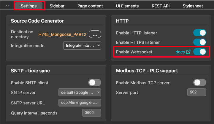
Gauge is a display element, which will display the value of the ADC. The UI can only display the data sent by the MCU. We can use websocket-updates to periodically send the values from MCU to the UI. We need to first enable the websocket-updates on the settings page of the UI.
Below is the image showing the configuration for the Gauge Element.
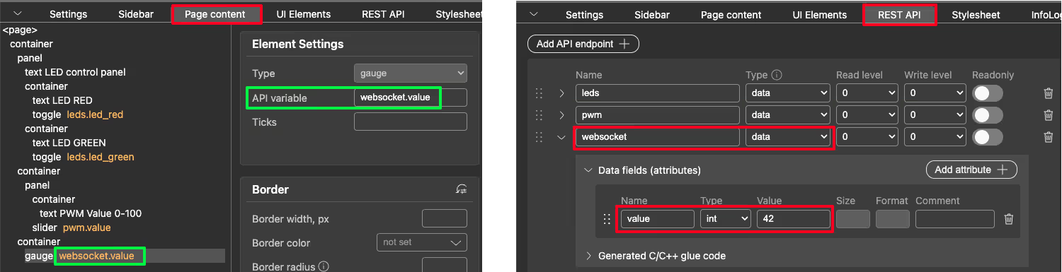
In the REST API section, I have created another API endpoint for the Gauge and named it websocket. If you want use websocket to send the value, it must be named as websocket. It should also of the type data, so basically a structure in C. value is the element of this structure. It is an integer type variable and the default value for this variable is set to 42.
On the page element section, set the API variable of the slider to the websocket.value endpoint. This way, each time the websocket structure is sent by the MCU with value element, the respective data will update to the Gauge.
Once all the modification is finished, click on Generate C/C++ code to generate the project.
CONFIGURE CUBEMX
Below is the final image of the project folder. It has the same structure as generated by the cubeMX, in addition to the mongoose folder. We will load this project directly in the cubeIDE and modify the .IOC file in the cubeMX.
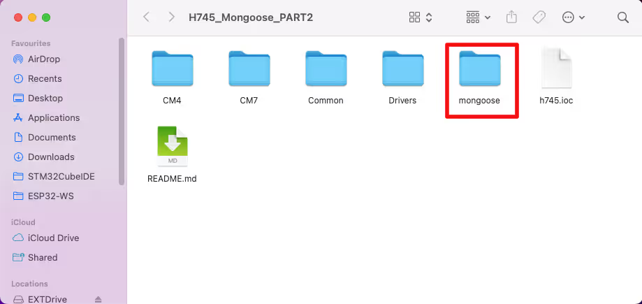
Let’s configure the LEDs, PWM and ADC in the cubeMX.
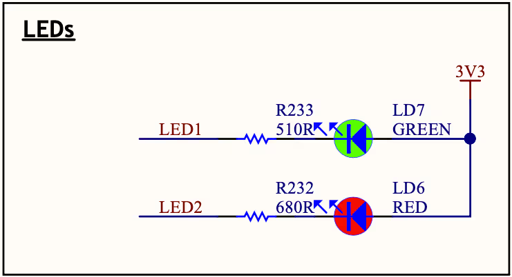
LED Configuration
STM32H745 Discover has 2 LEDs on board, one of them is connected to the pin PJ2 and another is connected to PI13. Both the LEDs are connected such that the negative terminals of the LEDs are connected to the respective pins while the positive terminals are connected to 3.3V. Hence the pins (PJ2 & PI13) must be pulled LOW to turn the LED ON and they should be pulled HIGH to turn the LED OFF.
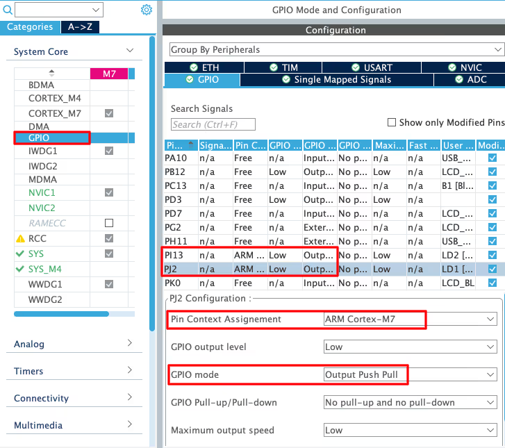
In the cubeMX, we just need to set the LED pins as output. Also if you are using a dual core processor, make sure the pins are assigned to the correct core.
PWM Configuration
We will use the PWM to vary the brightness of a LED which is connected externally. Below is the image showing the PWM configuration.
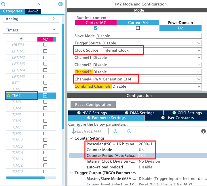
I am using the TIM2 Channel4 for the PWM. We are using the PWM to control the LED brightness, so the prescaler is not an issue. You can just set a random prescaler value.
The slider’s value in the UI can vary from 0 to 100, therefore the maximum ARR should be set to 100 in order to achieve maximum brightness.
ADC Configuration
Below is the image showing the ADC configuration.
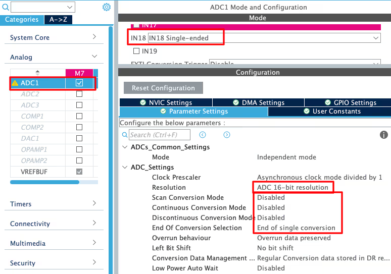
I am going to read ADC1 Channel18 in the polling mode. There is only a single conversion with continuous conversion being disabled. The ADC resolution is set to 16 bits.
THE CODE
The mongoose_glue.c file contains the getter and setter functions for the API variables. We need to edit these function in order to connect the UI elements to the board components.
LED Function
The function glue_set_leds is called each time toggle button related to leds API is changed. We can use this function to set or reset the state of the LED based on the value of the API variable
void glue_set_leds(struct leds *data) {
  s_leds = *data; // Sync with your device
  if (s_leds.led_green) HAL_GPIO_WritePin (GPIOJ, GPIO_PIN_2, 0);
  else HAL_GPIO_WritePin (GPIOJ, GPIO_PIN_2, 1);

  if (s_leds.led_red) HAL_GPIO_WritePin (GPIOI, GPIO_PIN_13, 0);
  else HAL_GPIO_WritePin (GPIOI, GPIO_PIN_13, 1);
}Inside this function, the LED data is stored in the s_leds structure. We will then check the members (led_green and led_red) of this structure and Set or Reset the LEDs based on the values of these members. Note that the LED is Set by Reseting the respective pin because the pin is connected to the negative terminal of the LED. Similarly, the pin must be Set to turn the LED OFF.
PWM Function
The PWM will be used to control the LED brightness. We need to define a separate function for the same in the main file. Below is the code for the main file.
void setPWM (int value)
{
  TIM2->CCR4 = value;
}
int main()
{
  ....
  HAL_TIM_PWM_Start(&htim2, TIM_CHANNEL_4);
  ....
  while(1){}
}Here inside the main function we will start the TIM2 Channel4 in the PWM mode.
The function setPWM will simply update the compare value in the TIM2 CCR4 (Capture Compare Register 4). It will update the duty cycle of the PWM signal, hence varying the brightness of the LED.
Inside the mongoose_glue.c file, we will define this setPWM as an external function.
extern void setPWM (int value);
void glue_set_pwm(struct pwm *data) {
  s_pwm = *data; // Sync with your device
  setPWM(s_pwm.value);
}The function glue_set_pwm is called each time slider related to pwm API is changed. Inside this function, the slider data is stored in the s_pwm structure. We will then check the member (value) of this structure and pass this value to the parameter of the function setPWM.
ADC Function
The function readADC is used to read the ADC value. The map function will convert the 16 bit ADC value in the range from 0 to 100, so that we can display it on the Gauge.
int readADC (void)
{
	HAL_ADC_Start (&hadc1);
	HAL_ADC_PollForConversion (&hadc1, 100);
	uint16_t ADC_VAL = HAL_ADC_GetValue (&hadc1);
	HAL_ADC_Stop (&hadc1);
	int val = map(ADC_VAL, 0, 65535, 0, 100);
	return val;
}As discussed earlier in the tutorial, we will use the websocket-updates to send the ADC values to the Gauge. Websocket is used to send frequent periodic updates to all connected Web UI clients. We can enable the websocket updates in 2 easy steps.
- Add the websocket handler in the main function.
- Write a websocket callback outside the main function.
static void my_ws(struct mg_connection *c) {
  mg_ws_printf(c, WEBSOCKET_OP_TEXT, "{\"value\": %d}", readADC());
}

int main()
{
  ....
  HAL_TIM_PWM_Start(&htim2, TIM_CHANNEL_4);
  mongoose_add_ws_handler(200, my_ws);
  run_mongoose();
  while(1){}
}Inside the main function we will call the function mongoose_add_ws_handler to add the websocket handler (my_ws) to run every 200ms. This callback (my_ws) is defined outside the main function.
Inside the websocket callback (my_ws) we will call the function mg_ws_printf to send the websocket structure to the UI. The websocket message structure is shown below.
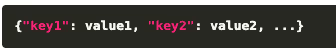
Here “key1” is the member of the websocket structure and value1 is the value of this member.
In the callback function, we are using the websocket message structure {\”value\”: %d}. Here “value” is the member of the websocket structure we defined in the UI and %d is the value of this member, which is fetched from the readADC function.
RESULT
Below are some gifs showing the output of the project.
LED Working
PWM Working
ADC Working
STM32 Mongoose Ethernet Tutorial Series
STM32 Ethernet with Mongoose | Part 3 Weather Station
STM32 Ethernet with Mongoose | Part 4 OTA Update
PROJECT DOWNLOAD
Subscribe
Login
0 Comments
Newest