Home ▸ STM32 Tutorials ▸ STM32 IoT ▸
Published: September 5, 2025
Last Updated: February 6, 2026
Last Updated: February 6, 2026
How to Connect STM32 to WiFi and Obtain IP Address
In this guide, we’ll start with STM32 IoT using the ESP8266 WiFi module. The goal is to connect the STM32 board to a WiFi network and get its IP address. This is the very first step in making an IoT project with STM32, where your microcontroller can talk to the internet. We’ll use UART communication and send simple ESP8266 AT commands from STM32CubeIDE to set up the WiFi connection. By the end, you’ll have a clear STM32 WiFi connection example and you’ll see exactly how to obtain the IP address from ESP8266 for further projects.
The STM32 microcontroller powers many IoT applications because it offers high performance, low power consumption, and supports many peripherals for sensors and communication. Developers often choose the ESP8266 module to add WiFi connectivity since it is low-cost, reliable, and easy to control with AT commands. In this tutorial, you will connect STM32 to WiFi using the ESP8266 and obtain the IP address. This basic step prepares you for advanced STM32 IoT projects, such as sending data to servers, cloud platforms, or mobile apps.

What is ESP8266 and Why Use It with STM32?
The ESP8266 is a low-cost WiFi module that makes it easy to add wireless connectivity to microcontrollers like STM32.
Its Key features include:
- UART interface for simple communication with STM32
- Support for AT commands to configure and control the module
- Built-in TCP/IP stack for handling network protocols
- Full WiFi support with easy integration into embedded projects
Why Use ESP8266 in IoT Projects?
Developers widely use the ESP8266 in STM32 IoT applications because it offers many benefits:
- Low cost and easily available for development
- Power efficient, suitable for battery-powered devices
- Reliable WiFi connection for sending and receiving data
- Simple integration with STM32 through serial UART
- A proven choice for WiFi module in STM32 projects
With STM32 managing processing and sensors, and ESP8266 handling the WiFi connection, this combo is ideal for building connected devices and practical IoT solutions.
STM32 ESP8266 Wifi Project Requirements
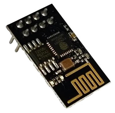
I am going to use the STM32F446 Dev board from WeAct Studio along with the ESP8266-01 WiFi transceiver Module for this series.
We’ve added affiliate links for your convenience — if you purchase through these links, it helps support our work at no extra cost to you.
- STM32F446 Dev Board
- ST-Link V2
- ESP8266-01 WiFi transceiver
- ESP-01 Adapter
- FT232 USB to TTL Converter
- Jumper Wires
Wiring STM32 with ESP8266
To connect the ESP8266 WiFi module with STM32, we use the UART pins for communicating with the module. Along with the basic connections (power, TX, RX, and GND), adding a USB to TTL converter is very handy for debugging and logging, so you can easily see what’s happening during the STM32 WiFi setup.
Connecting ESP8266 directly with STM32
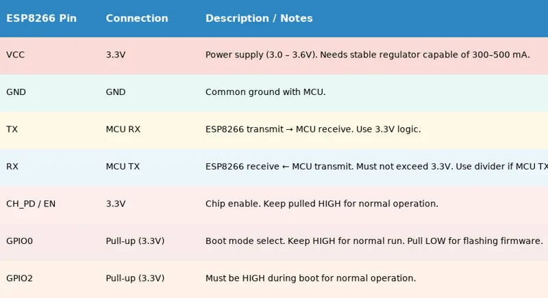
The ESP8266-01 module has 8 pins that need to be connected to the MCU. If you are wiring it directly, the table below shows the correct pin connections.
Connecting ESP8266 using the ESP-Adapter
I’m using an ESP-01 Adapter with the ESP8266-01 module. This adapter makes things easier by reducing the connections from 8 pins to just 4. The image below shows how the module is connected using the adapter.
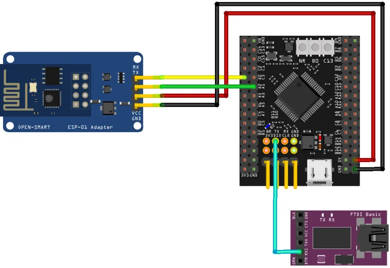
Always make UART connections in a cross pattern: connect TX to RX and RX to TX.
- Connect the TX pin from the Adapter to PA0 (UART4_RX) and the RX pin to PA1 (UART4_TX).
- Power the Adapter with 5V from the MCU. The ST-Link provides only 3.3V, so connect the USB cable to the dev board to supply 5V.
The Adapter’s onboard voltage regulator converts 5V to 3.3V for the ESP8266-01 module. If you use an external power supply for the module, ensure the supply and STM32 dev board share a common ground.
FTDI (FT232) Module
We use it to view user interaction logs on the serial console. Since we only send data from STM32 to the FTDI, connect PA10 (UART1_TX) to the RX pin of the module.
STM32 CubeMX Configuration
We will start configuring the UART4 to connect the ESP8266-01 module.
UART4 (ESP8266) Configuration
The image below shows the UART4 configuration.
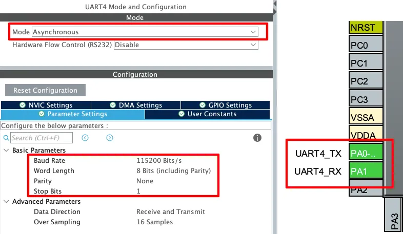
The UART must be configured in the Asynchronous mode. Leave the Parameter configuration to default, with 8 bits Word Length, no Parity and 1 Stop bit. The pins PA0 and PA1 are configured as the UART TX and RX pins.
The Baud Rate configuration here should match the Baud Rate of the ESP8266 Module. The default baud rate of ESP8266-01 is 115200, but you should still test it prior connecting to the MCU.
You check the video to see how to test the module to find the correct baud rate.
UART1 (FT232) Configuration
As I mentioned earlier, the user interactive logs will be sent through UART1 to the FT232, which will then be displayed on the serial console. The image below shows the UART1 configuration.
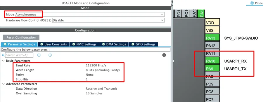
The UART1 is configured in the Asynchronous mode. The Baud rate is set to 115200 Bits/s with 8 Bits of word length, No parity and 1 Stop bit. We can configure this however we want, but this is an optimal configuration.
The pins PA9 and PA10 are configured as the UART1_TX and UART1_RX pins respectively. Since we only need to transmit data to the FTDI, PA9 (UART1_TX) is connected to FTDI RX as mentioned in the wiring diagram.
Adding the Library Files
After downloading the project from the link provided at the end of this post, you can extract the ESP8266_STM32.c file from the src folder and ESP8266_STM32.h file from the inc folder. You need to copy these files in the exact same folders inside your project.
You can customize the UART instance in the ESP8266_STM32.h file as shown below.
/* ------------ USER CONFIG ------------- */
#define ESP_UART       huart4   // UART connected to ESP8266

// Enable/Disable logs
#define ENABLE_USER_LOG   1
#define ENABLE_DEBUG_LOG  0
/* -------------------------------------- */I am using the UART4, so it is configured as the ESP_UART. If you are using some other instance, define it here.
You should enable USER_LOGS to see the main process messages on the serial console. If something goes wrong while initializing or connecting to WiFi, you can turn on DEBUG_LOGS to get detailed step-by-step information about what caused the error.
STM32 HAL Code to Communicate with ESP8266
Before writing the main code we will first understand how the library communicates with the module. We need to use the AT command set to communicate with the module.
How to Send Command and Check Response
Below is function to send the command to the device and check the response sent by the device.
static ESP8266_Status ESP_SendCommand(const char *cmd, const char *ack, uint32_t timeout)
{
    uint8_t ch;
    uint16_t idx = 0;
    uint32_t tickstart;
    int found = 0;

    memset(esp_rx_buffer, 0, sizeof(esp_rx_buffer));
    tickstart = HAL_GetTick();

    if (strlen(cmd) > 0)
    {
        DEBUG_LOG("Sending: %s", cmd);
        if (HAL_UART_Transmit(&ESP_UART, (uint8_t*)cmd, strlen(cmd), HAL_MAX_DELAY) != HAL_OK)
            return ESP8266_ERROR;
    }

    while ((HAL_GetTick() - tickstart) < timeout && idx < sizeof(esp_rx_buffer) - 1)
    {
        if (HAL_UART_Receive(&ESP_UART, &ch, 1, 10) == HAL_OK)
        {
            esp_rx_buffer[idx++] = ch;
            esp_rx_buffer[idx]   = '\0';

            // check for ACK
            if (!found && strstr(esp_rx_buffer, ack))
            {
                DEBUG_LOG("Matched ACK: %s", ack);
                found = 1; // mark as found but keep reading
            }

            // handle busy response
            if (strstr(esp_rx_buffer, "busy"))
            {
                DEBUG_LOG("ESP is busy... delaying before retry");
                HAL_Delay(1500);
                idx = 0;
                memset(esp_rx_buffer, 0, sizeof(esp_rx_buffer));
                continue;
            }
        }
    }

    if (found)
    {
        DEBUG_LOG("Full buffer: %s", esp_rx_buffer);
        return ESP8266_OK;
    }

    if (idx == 0)
        return ESP8266_NO_RESPONSE;

    DEBUG_LOG("Timeout or no ACK. Buffer: %s", esp_rx_buffer);
    return ESP8266_TIMEOUT;
}The function ESP_SendCommand() is used to send an AT command from STM32 to the ESP8266 over UART and check if the expected response (ACK) is received. It also handles timeouts and busy states.
The parameters of this function are:
const char *cmd→ The AT command string to send (e.g.,"AT+RST\r\n").const char *ack→ The expected response or acknowledgment string (e.g.,"OK").uint32_t timeout→ Maximum time (in milliseconds) to wait for the response.
Main steps of this function are:
- Clear buffer and start timer – It resets the receive buffer and notes the start time for timeout checking.
- Send the AT command – If a valid command string is given, it transmits it over UART to the ESP8266.
- Receive response – Continuously reads incoming characters (one at a time) from ESP8266 until timeout or buffer is full.
- Check for ACK – Looks for the expected acknowledgment string (like “OK“) in the response.
- Handle busy state – If the ESP8266 replies with “busy”, it waits and retries.
- Return status – Based on results, it returns
ESP8266_OK,ESP8266_ERROR,ESP8266_NO_RESPONSE, orESP8266_TIMEOUT.
Initializing the ESP8266 Module
The module doesn’t require any special initialization. Here, we’ll just test if the communication with STM32 is working correctly. The function below is used to check the communication with the module.
ESP8266_Status ESP_Init(void)
{
	ESP8266_Status res;
	USER_LOG("Initializing ESP8266...");
	HAL_Delay(1000);

    res = ESP_SendCommand("AT\r\n", "OK", 2000);
    if (res != ESP8266_OK){
    	DEBUG_LOG("ESP8266 Not Responding...");
    	return res;
    }

    res = ESP_SendCommand("ATE0\r\n", "OK", 2000); // Disable echo
    if (res != ESP8266_OK){
    	DEBUG_LOG("Disable echo Command Failed...");
    	return res;
    }
    USER_LOG("ESP8266 Initialized Successfully...");
    return ESP8266_OK;
}The ESP_Init() function is used to check if the ESP8266 module is responding.
Main steps of this function are:
- Start initialization → Logs a message and waits for 1 second to let the ESP8266 power up.
- Send basic AT command → Sends
"AT\r\n"and expects"OK". This checks if communication is working. - Check response → If no
"OK"is received, it means the ESP8266 is not responding, and the function returns an error. - Disable echo → Sends
"ATE0\r\n"to turn off command echo, so responses are easier to parse. - Verify echo command → If disabling echo fails, it returns an error.
- Finish successfully → If both checks pass, it confirms that the ESP8266 is initialized and ready.
Connecting the Module to Wifi Network
Here we will see how to connect the ESP8266 module to WiFi Network and obtain the IP Address. The function below is used to do the same.
ESP8266_Status ESP_ConnectWiFi(const char *ssid, const char *password, char *ip_buffer, uint16_t buffer_len)
{
    USER_LOG("Setting in Station Mode");
    // Set in Station Mode
    char cmd[128];
    snprintf(cmd, sizeof(cmd), "AT+CWMODE=1\r\n");

    ESP8266_Status result = ESP_SendCommand(cmd, "OK", 2000); // wait up to 2s
    if (result != ESP8266_OK)
    {
    	USER_LOG("Station Mode Failed.");
        return result;
    }

    USER_LOG("Connecting to WiFi SSID: %s", ssid);
    // Send join command
    snprintf(cmd, sizeof(cmd), "AT+CWJAP=\"%s\",\"%s\"\r\n", ssid, password);

    result = ESP_SendCommand(cmd, "WIFI CONNECTED", 10000); // wait up to 10s
    if (result != ESP8266_OK)
    {
    	USER_LOG("WiFi connection failed.");
        ESP_ConnState = ESP8266_NOT_CONNECTED;
        return result;
    }

    USER_LOG("WiFi Connected. Waiting for IP...");
    ESP_ConnState = ESP8266_CONNECTED_NO_IP;
    // Fetch IP with retries inside ESP_GetIP
    result = ESP_GetIP(ip_buffer, buffer_len);
    if (result != ESP8266_OK)
    {
    	USER_LOG("Failed to fetch IP. Status=%d", result);
        return result;
    }

    USER_LOG("WiFi + IP ready: %s", ip_buffer);
    return ESP8266_OK;
}The ESP_ConnectWiFi() function connects the ESP8266 to a WiFi network using the given SSID and password, then retrieves the assigned IP address.
The parameters of this function are:
const char *ssid→ The WiFi network name you want to connect to.const char *password→ The WiFi password for authentication.char *ip_buffer→ A buffer where the obtained IP address will be stored.uint16_t buffer_len→ The length of the IP buffer.
Main steps of this function are:
- Set Station Mode → Sends
"AT+CWMODE=1"so ESP8266 works as a client device and waits for the confirmation ("OK"). - Connect to WiFi → Sends
"AT+CWJAP="SSID","PASSWORD""with given credentials. - Wait for confirmation → Looks for
"WIFI CONNECTED"in the response. - Fetch IP address → Calls
ESP_GetIP()to obtain the IP address and stores the result inip_buffer. - Return status → Returns
ESP8266_OKif successful, otherwise returns an error code.
The ESP_GetIP() function sends another command, "AT+CIFSR\r\n" to obtain the IP address of the module. The IP address returned by the ESP8266 is in the format +CIFSR:STAIP,"192.168.1.7".
The ESP_GetIP() function looks for the string "STAIP," in the response buffer. Once found, it copies the IP address that comes after this string into the ip_buffer. The code snippet for this is shown below.
char *search = esp_rx_buffer;
        char *last_ip = NULL;

        while ((search = strstr(search, "STAIP,")) != NULL)
        {
            char *ip_start = strstr(search, "STAIP,\"");
            if (ip_start)
            {
                ip_start += 7;
                char *end = strchr(ip_start, '"');
                if (end && ((end - ip_start) < buffer_len))
                {
                    last_ip = ip_start;
                }
            }
            search += 6;
        }

        if (last_ip)
        {
            char *end = strchr(last_ip, '"');
            strncpy(ip_buffer, last_ip, end - last_ip);
            ip_buffer[end - last_ip] = '\0';

            if (strcmp(ip_buffer, "0.0.0.0") == 0)
            {
            	DEBUG_LOG("Attempt %d: IP not ready yet (0.0.0.0). Retrying...", attempt);
                ESP_ConnState = ESP8266_CONNECTED_NO_IP;
                HAL_Delay(1000);
                continue;
            }

            DEBUG_LOG("Got IP: %s", ip_buffer);
            ESP_ConnState = ESP8266_CONNECTED_IP;
            return ESP8266_OK;
}STM32 HAL main function
The main() function below shows how to initialize the ESP8266 with STM32, connect it to WiFi, and fetch its IP address.
#include "ESP8266_STM32.h"

int _write(int file, char *ptr, int len) {
	HAL_UART_Transmit(&huart1, (uint8_t *)ptr, len, 100);
	return len;
}

char ip_buf[16];

int main()
{
  ....
  if (ESP_Init() != ESP8266_OK){
	  USER_LOG("Failed to initialize... Check Debug logs");
	  Error_Handler();
  }

  if (ESP_ConnectWiFi("Arun_Rawat", "arun@321", ip_buf, sizeof(ip_buf)) != ESP8266_OK){
	  USER_LOG("Failed to connect to wifi... Check Debug logs");
	  Error_Handler();
  }
  while (1)
  {}
}Inside the main file, we will first define a custom _write function to route the printf output to the UART1. The UART1 TX pin is connected to FT232, so we will be able to view the logs on the serial console.
Key parts of the code:
- IP buffer →
char ip_buf[16];is created to store the ESP8266’s IP address once it connects. - Initialize ESP8266 →
ESP_Init()checks communication with the module and disables command echo. If this fails, the program stops inError_Handler(). - Connect to WiFi →
ESP_ConnectWiFi("Arun'WiFi", "12345678", ip_buf, sizeof(ip_buf))tries to join the given WiFi network and fetches the assigned IP intoip_buf. On failure, it logs the error and stops.
Result of STM32 communication with ESP8266
Next, we can check the project output by analyzing the messages shown in USER_LOGS and, at the same time, reviewing the detailed information from DEBUG_LOGS.
USER LOGS
The image below shows the console output when only USER_LOGS are enabled.
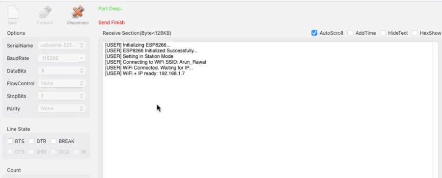
As you can see in the image, USER_LOGS only prints the important information on the console. It is as follows:
- ESP8266 initialization starts and succeeds.
- Module sets in Station Mode.
- ESP8266 tries to connect to the WiFi network Arun_Rawat.
- Connection is successful, waiting for IP.
- The IP address obtained is: 192.168.1.7.
DEBUG LOGS
The image below shows the console output with both USER_LOGS and DEBUG_LOGS enabled.
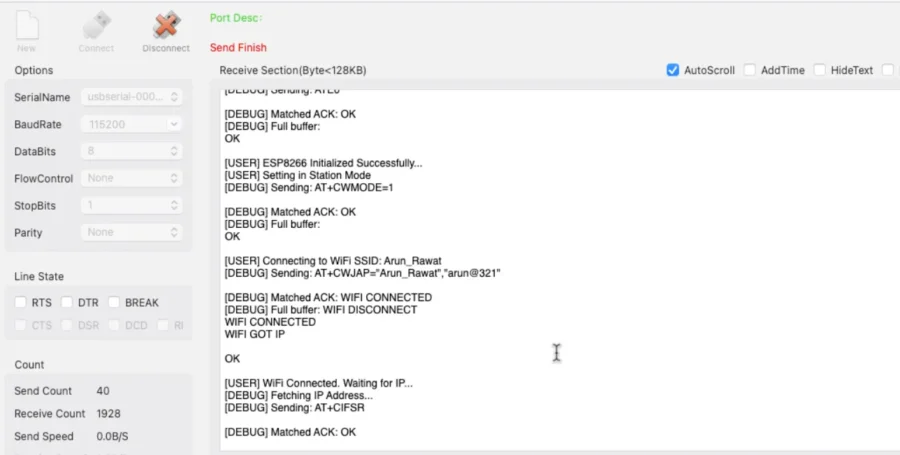
DEBUG_LOGS displays a step-by-step trace of the process. It prints each command sent to the ESP8266, shows the raw data received, and verifies whether the expected ACK matches. This makes it easy to spot where things fail—init, mode set, WiFi join, or IP fetch.
Video Tutorial
STM32 ESP8266 Video Tutorial
While the written guide below provides all the details and code for reference, sometimes a visual demonstration can make all the difference. I’ve created a complete video walkthrough that runs through the entire process in real-time. Follow the written steps here while watching the implementation in the video to solidify your understanding and catch any subtle details
Watch the VideoConclusion
In this first part, we were able to connect the STM32 to WiFi using the ESP8266 module and also obtain the IP address. This means our STM32 is now ready to be used in real IoT projects.This was just the beginning. In the next parts of this series, we will learn how to set up TCP communication and send sensor data to a cloud server. That’s where our IoT application will really come to life.
Browse More STM32 Iot Tutorials
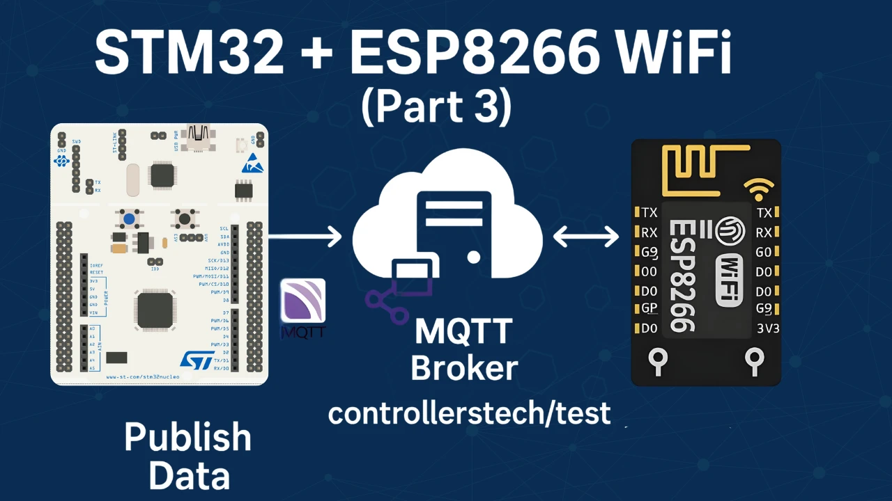
STM32 IoT with ESP8266 (Part 3): MQTT Connect and Publish messages
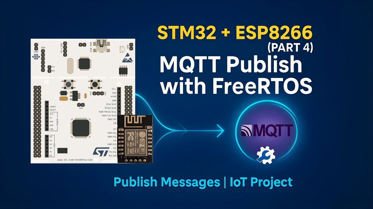
STM32 IoT with ESP8266 (Part 4): Publish MQTT messages with RTOS
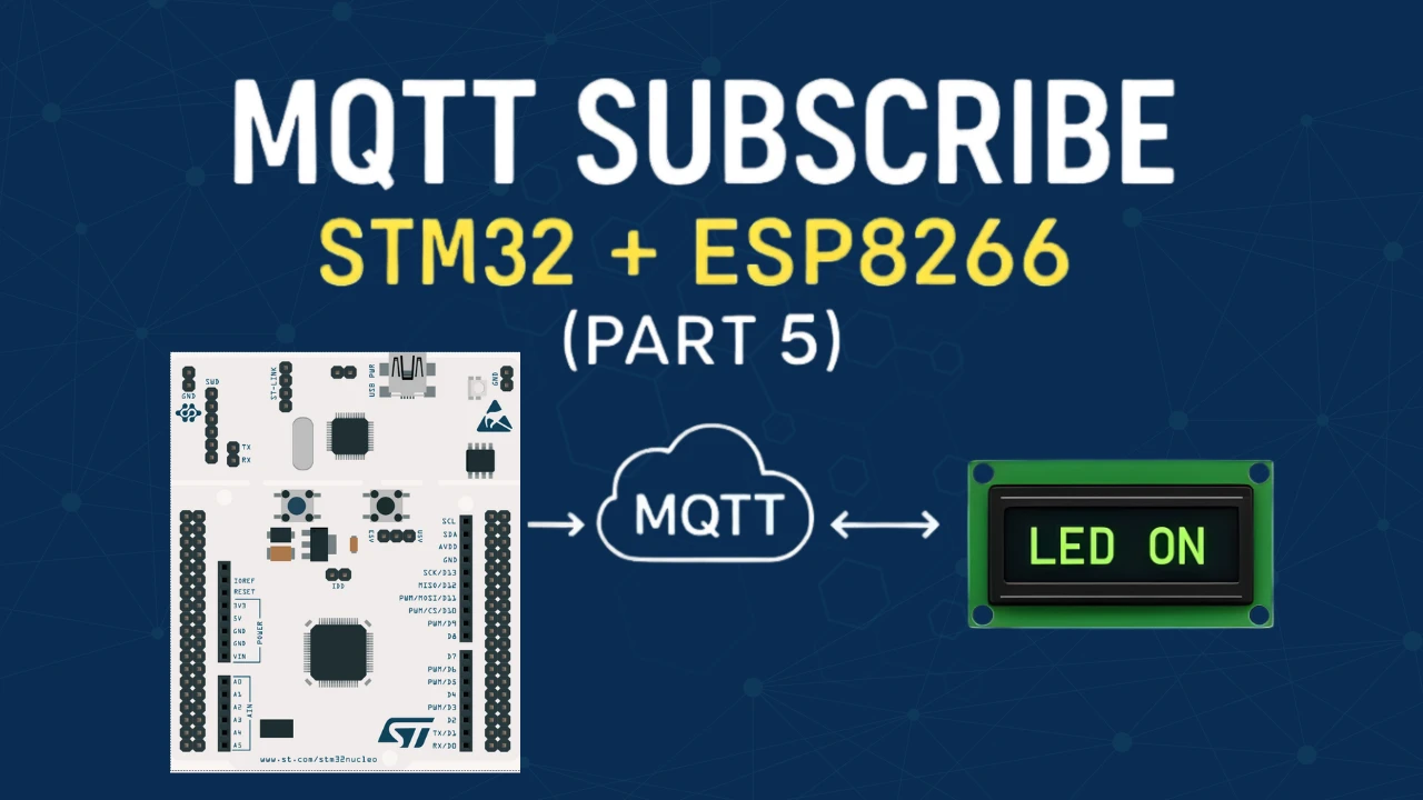
STM32 IoT Tutorial (Part 5): MQTT Subscribe with ESP8266, DMA & FreeRTOS
STM32 ESP8266 WiFi Project Download
STM32 ESP8266 WiFi Project FAQs
Subscribe
Login
0 Comments
Newest
