
Home ▸ STM32 Tutorials ▸ STM32 IoT ▸
Published: October 3, 2025
Last Updated: February 6, 2026
Last Updated: February 6, 2026
How to Subscribe to MQTT Topic and receive messages using DMA
In this tutorial, we will dive into the process of subscribing to multiple topics over MQTT, learning how to receive incoming messages from those topics and effectively utilize the data within your STM32 applications. Along the way, we will also integrate UART communication using DMA (Direct Memory Access) to interface with the ESP8266 module. By leveraging DMA, we can significantly enhance the efficiency and speed of data transfer, reducing CPU overhead and improving overall system performance.
This lesson marks the fifth tutorial in the STM32 IoT series with ESP8266, where we continue building practical skills for developing connected and responsive IoT applications.
Prerequisites:
This tutorial is Part 5 of the STM32 IoT series with ESP8266. In the earlier parts of this series, we learned how to connect and configure the ESP8266 with STM32, and how to register the STM32 client with an MQTT broker to publish messages to different topics using the FreeRTOS.
In this tutorial we will also use the LCD1602, connected via I2C, to display the received messages from the MQTT Topics. I have already covered another tutorial explaining how to connect the LCD16x2 with STM32 using I2C.
If you haven’t followed those tutorials yet, I recommend going through them first before continuing with this one:
STM32 MQTT Project Requirements
Before we begin building our STM32 ESP8266 MQTT project, let’s take a quick look at the tools and components you’ll need. This includes both hardware and software required for the project.
- Hardware:
- Software:
- STM32CubeIDE
- MQTT Broker (I am going to use the HiveMQ Public broker for testing)
- MQTT Client (Optional us it for testing)
- Internet access
Connecting STM32 and ESP8266 for MQTT
To connect the ESP8266 WiFi module with STM32, we use the UART pins for communicating with the module. Along with the basic connections (power, TX, RX, and GND), adding a USB to TTL converter is very handy for debugging and logging, so you can easily see what’s happening during the STM32 WiFi setup.
Hardware Connections and Pin Configuration
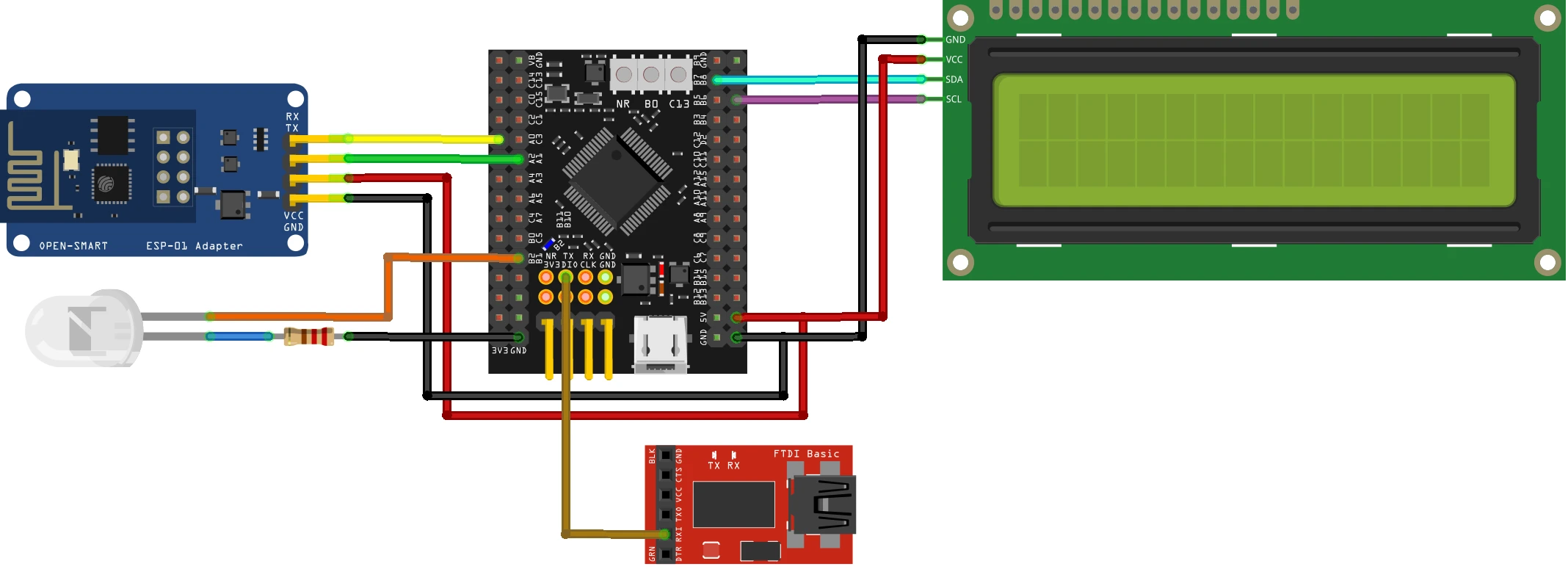
I’m using an ESP-01 Adapter with the ESP8266-01 module. This adapter makes things easier by reducing the connections from 8 pins to just 4. The image below shows how the module is connected using the adapter.
Always make UART connections in a cross pattern: connect TX to RX and RX to TX.
- Connect the TX pin from the Adapter to PA0 (UART4_RX) and the RX pin to PA1 (UART4_TX).
- Power the Adapter with 5V from the MCU. The ST-Link provides only 3.3V, so connect the USB cable to the dev board to supply 5V.
The Adapter’s onboard voltage regulator converts 5V to 3.3V for the ESP8266-01 module. If you use an external power supply for the module, ensure the supply and STM32 dev board share a common ground.
FTDI (FT232) Module
We use it to view user interaction logs on the serial console. Since we only send data from STM32 to the FTDI, connect PA10 (UART1_TX) to the RX pin of the module.
I2C LCD1602
The LCD16x2 is connected using the PCF8574 via the I2C1 peripheral. The Pins PB6 (I2C1_SCL) is connected to SCL of the module and PB7 (I2C1_SDA) is connected to the SDA of the module. The STM32 will use the LCD1602 to display the messages received from the subscribed topic over MQTT.
I have already explained how to interface I2C LCD1602 with STM32, so if you haven’t seen it yet, please go through the tutorial.
LED Connection
I have also connected an LED to pin PB2. The STM32 will control the LED using the messages received from the topic over MQTT. STM32 pin outputs 3.3V, so make sure to connect a resistor (200Ω) in series to reduce the voltage drop on the LED.
STM32 ESP8266 CubeMX Configuration
We will start configuring the UART4 to connect the ESP8266-01 module.
UART4 (ESP8266) Configuration
The image below shows the UART4 configuration.
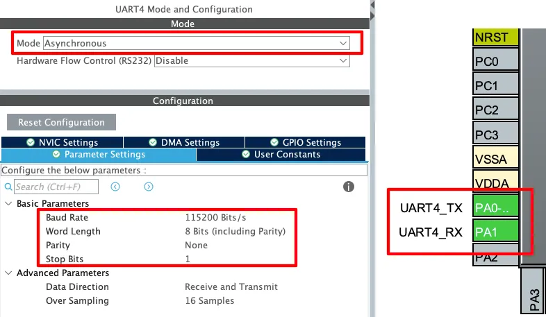
The UART must be configured in the Asynchronous mode. Leave the Parameter configuration to default, with 8 bits Word Length, no Parity and 1 Stop bit. The pins PA0 and PA1 are configured as the UART TX and RX pins.
The Baud Rate configuration here should match the Baud Rate of the ESP8266 Module. The default baud rate of ESP8266-01 is 115200, but you should still test it prior connecting to the MCU.
You check the video to see how to test the module to find the correct baud rate.
We will also implement the DMA for receiving the data from the UART. The image below shows the DMA configuration for UART4.
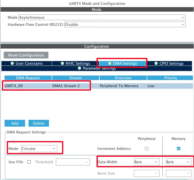
I have enabled DMA only for the RX (receive) mode. When configuring DMA, ensure that it is set to Circular mode and the Data width is configured as Byte. In Circular mode, the DMA continuously receives incoming data without requiring CPU intervention. All received data is stored in the DMA RX buffer, which we can access at any time.
However, it’s important to note that when checking for acknowledgments of specific commands, we must carefully read the correct portion of the buffer. Since DMA operates continuously, new data can overwrite older data if the buffer becomes full. We will handle this scenario properly in the code implementation.
UART1 (FT232) Configuration
As I mentioned earlier, the user interactive logs will be sent through UART1 to the FT232, which will then be displayed on the serial console. The image below shows the UART1 configuration.
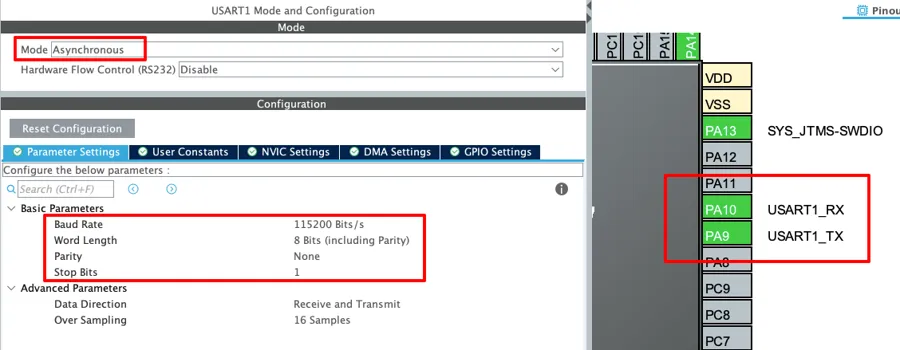
The UART1 is configured in the Asynchronous mode. The Baud rate is set to 115200 Bits/s with 8 Bits of word length, No parity and 1 Stop bit. We can configure this however we want, but this is an optimal configuration.
The pins PA9 and PA10 are configured as the UART1_TX and UART1_RX pins respectively. Since we only need to transmit data to the FTDI, PA9 (UART1_TX) is connected to FTDI RX as mentioned in the wiring diagram.
I2C LCD Configuration
The image below shows the I2C1 configuration for connecting the LCD1602.
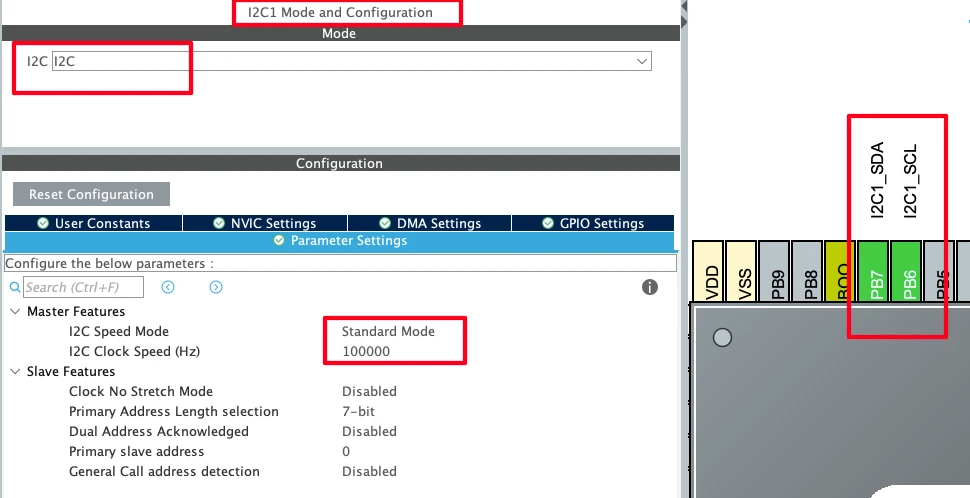
The I2C1 peripheral is configured in its default mode with the clock speed set to 100 kHz. There is no need to modify any of the default parameters for our setup. By default, the pins PB6 and PB7 are assigned as I2C1_SCL (clock) and I2C1_SDA (data), respectively. These are the pins to which the LCD will be connected.
LED Configuration
The LED is connected to pin PB2, therefore, I have configured the pin as output.
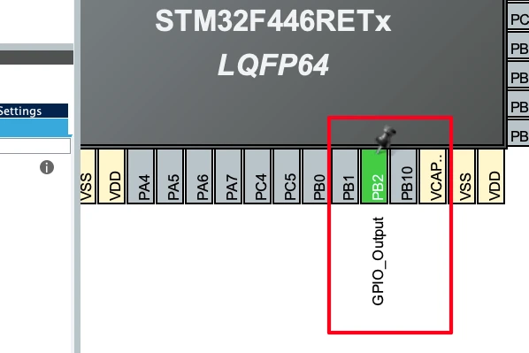
The STM32 will control the LED using the messages received on the topic over the MQTT.
STM32 MQTT FreeRTOS Configuration
After configuring the UART peripherals to connect the hardwares, we will now configure the FreeRTOS. The image below shows the parameter configuration for the FreeRTOS.
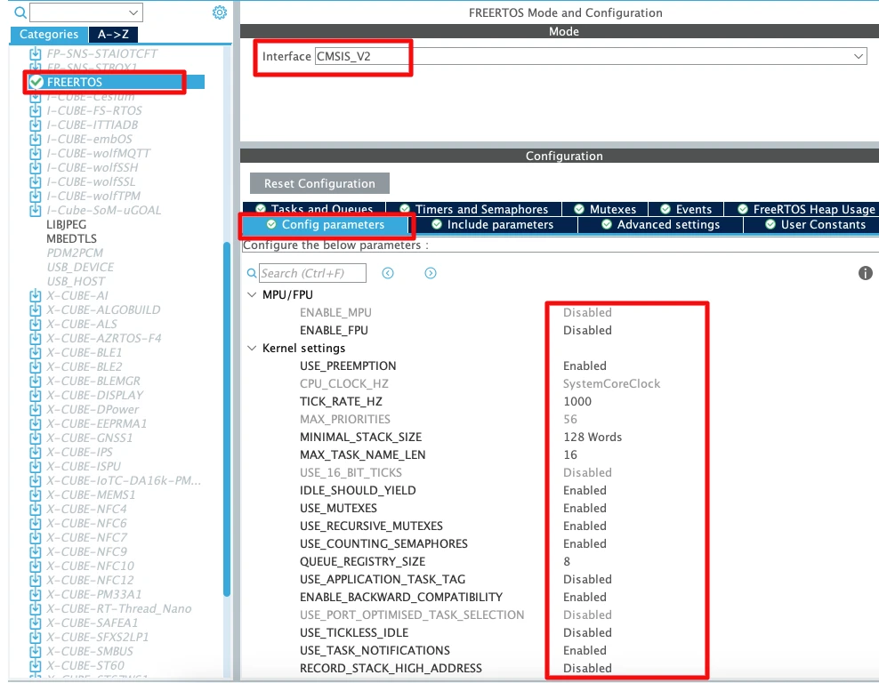
I have enable the CMSIS_V2 for the RTOS. The parameters are configured in their default state, I have not modified anything at all.
Create MQTT Tasks
Next, go to “Tasks and Queues” section to add Tasks and Queues. We will start by adding the Tasks first. The images below shows the configuration for the Three tasks we will use in this project.
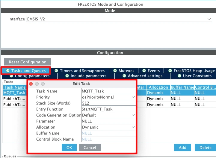
The MQTT_Task will handle the publishing part. It will receive the data from the queue and publish the message to the respective topic. You should use the stack size of at least 512 words and priority higher than the other tasks. This is to make sure that the task is not preempted, specially when it is publishing data.
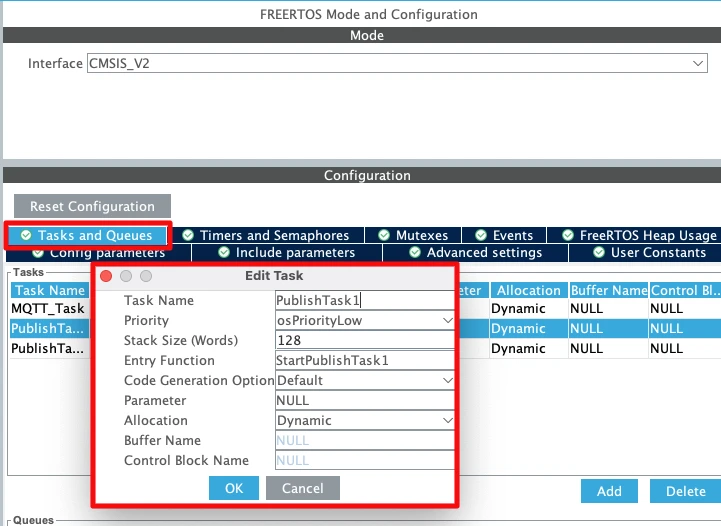
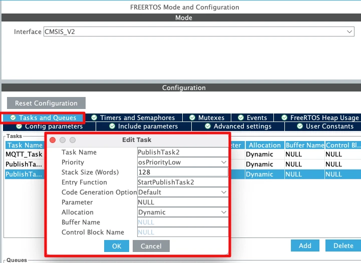
The PublishTask1 and PublishTask2 will send the message to be published and topic names to the queue. This data will then pass to the MQTT_Task, which will actually call the publish function.
You should keep the priorities of these tasks lower than the MQTT_Task.
Create MQTT Publish Queue
We will create a Queue to pass the data from PublishTask to MQTT_Task. The image below shows the queue.
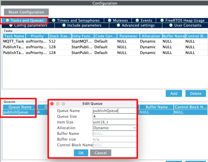
The PublishQueue has space for 4 elements. This is enough since we have only 2 publish tasks sending data via this queue. Note that the Item Size is 16 bits, but we will change this later in the code after we create a structure for the data. You can read more about using Queue in FreeRTOS in another tutorial → Queue in STM32 FreeRTOS.
Understanding MQTT Subscribe Packet
I have already explained the MQTT publish function and how to use it in the previous tutorial → STM32 MQTT connect and Publish, therefore I will skip the explanation here. We will only focus on the new packet, Subscribe Packet.
MQTT Subscribe Packet Structure Explained
The Subscribe packet is sent by the client to the MQTT broker when it wants to receive messages from specific topics. It tells the broker exactly which topics the client is interested in, along with the desired Quality of Service (QoS) level for each subscription.
The Subscribe packet is divided into three parts:
- Fixed Header – This section defines the packet type (for Subscribe, it is
0x82) and the remaining length of the packet. - Variable Header – For the Subscribe packet, this contains the Packet Identifier, which is used to match the subscription with its acknowledgment (SUBACK) from the broker.
- Payload – This carries the list of topic filters the client wants to subscribe to, along with the requested Quality of Service (QoS) level for each topic.
The image below shows an example of the Subscribe packet containing username and password.
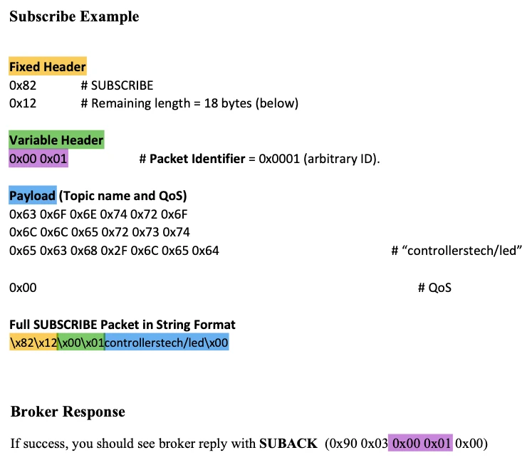
This image illustrates the composition of an MQTT SUBSCRIBE packet. The packet is divided into three logical sections: Fixed Header, Variable Header, and Payload.
- Fixed Header – This section specifies the type of packet, which in this case is a SUBSCRIBE request (
0x82). It also indicates the remaining length of the packet, so the broker knows how many bytes to process for the subscription request. - Variable Header – The variable header contains the Packet Identifier, which uniquely identifies the subscription request. This ID allows the broker to match the subscription with its acknowledgment (SUBACK) and ensures reliable delivery tracking. I am setting it to 0x00 0x01, so the same ID is expected from the broker while receiving the SUBACK.
- Payload – The payload carries the list of topic filters the client wants to subscribe to, along with the requested Quality of Service (QoS) level for each topic. In this example, the payload contains the topic name “controllerstech/led” and QoS 0.
At the bottom, the complete packet is shown in its raw byte-stream form, representing the exact sequence of bytes transmitted by the STM32 through the ESP8266 to the MQTT broker.
Once the broker receives this packet and processes it, it responds with a SUBACK packet, confirming that the client is now successfully subscribed to the requested topics.
Note that the Broker response will contain the same ID (Purple colour), which the client sent in the variable header. This implies that the broker has accepted the request for this particular subscription.
Writing the MQTT Subscribe Function
The ESP_MQTT_Subscribe() function is responsible for Subscribing to a given MQTT topic with a specified QoS level. It builds the MQTT subscribe packet, instructs the ESP8266 to send it, and waits for confirmation from the broker.
Building the Subscribe Packet
The packet is created in three parts:
- Fixed Header
- The first byte identifies the control packet type as SUBSCRIBE (0x30). The second byte (Remaining Length) is calculated later and updated once the full packet size is known.
    /* Fixed Header */
    packet[len++] = 0x82;   // SUBSCRIBE
int remLenPos = len++;- Variable Header
- Contains the Packet Identifier (arbitrary ID), which can be used to identify the correct Acknowledgement sent by the broker.
    /* Variable Header: Packet Identifier */
    packet[len++] = 0x00;
packet[len++] = 0x01;- Payload
- The Payload contains topic filters, topic name and Quality of Service (QoS).
    /* Payload: Topic */
    uint16_t tlen = strlen(topic);
    packet[len++] = tlen >> 8;
    packet[len++] = tlen & 0xFF;
    memcpy(&packet[len], topic, tlen); len += tlen;
packet[len++] = qos; // Requested QoS- Remaining Length
- After packet construction, the remaining length is written back into the header.
// Remaining length
packet[remLenPos] = len - 2; // remove first 2 bytes of Fixed HeaderSending Messages to a Specific Topic
Once the packet is built, the ESP8266 must be instructed to send it to the broker:
- Tell ESP how many bytes to send
- The
AT+CIPSENDcommand specifies the length of the upcoming packet.
- The
/****** Step 2: Tell ESP how many bytes to send  ******/
snprintf(cmd, sizeof(cmd), "AT+CIPSEND=%d\r\n", len);
res = ESP_SendCommand(cmd, ">", 2000);
if (res != ESP8266_OK){
	DEBUG_LOG("CIPSEND Failed with ESP ERROR %d..", res);
	return res;
}- Send the actual binary packet
- The packet is then transmitted, and the function waits for
"0x90"from the broker.
- The packet is then transmitted, and the function waits for
    /****** Step 3: Send packet and wait for PINGRESP (0xD0 0x00) ******/
    res = ESP_SendBinary(packet, len, "\x90", 5000); // SUBACK = 0x90
if (res != ESP8266_OK) return res;If both steps succeed, the STM32 will subscribe to the topic successfully.
Handle the incoming MQTT Data
The function ESP_MQTT_HandleIncoming will be used to handle the incoming data. This function will extract the useful information like topic name and message from the received data and store this information in the buffers passed to its parameters.
The ESP_MQTT_HandleIncoming function is shown below.
ESP8266_Status ESP_MQTT_HandleIncoming(char *topic_buffer, uint16_t topic_buf_len, char *msg_buffer, uint16_t msg_buf_len)The parameters of this function are as follows:
- @
topic_bufferis the buffer where we want to store the topic name extracted from the received data. - @
topic_buf_lenis the length of the buffer. - @
msg_bufferis the buffer where we want to store the message extracted from the received data. - @
msg_buf_lenis the length of the message buffer.
STM32 MQTT HAL Example Code
Let’s walk through a simple example where an STM32 device connects to a public MQTT broker, subscribe to two different topics and continuously publishes data to two separate topics.
Inside the main function, after the STM32 connects to the Wifi Network, it connects to the free HiveMQ broker, then subscribe to two topics, controllerstech/lcd and controllerstech/led.
  if (ESP_Init() != ESP8266_OK){
	  USER_LOG("Failed to initialize... Check Debug logs");
	  Error_Handler();
  }

  if (ESP_ConnectWiFi("Arun_Rawat", "arun@321", ip_buf, sizeof(ip_buf)) != ESP8266_OK){
	  USER_LOG("Failed to connect to wifi... Check Debug logs");
	  Error_Handler();
  }

  if (ESP_MQTT_Connect("broker.hivemq.com", 1883, "STM32Client", NULL, NULL, 30) != ESP8266_OK){
	  Error_Handler();
  }

  if (ESP_MQTT_Subscribe("controllerstech/lcd", 0) != ESP8266_OK){
	  Error_Handler();
  }

  if (ESP_MQTT_Subscribe("controllerstech/led", 0) != ESP8266_OK){
	  Error_Handler();
}Create a structured queue
The Queue we defined in the CubeMX is a simple queue with 16 bit element size. We want the PublishTasks to send topic name and message to the queue, hence a 16 bit element won’t be enough to store this information. Therefore we need to create a structured queue.
We will start with creating a structure first.
typedef struct {
	char topic[64];
	char message[64];
} publishQueue_t;This structure contains two arrays, one for the topic name and another for the message. Next we will edit the Queue definition to change it to structured queue.
/* creation of publishQueue */
publishQueueHandle = osMessageQueueNew (4, sizeof(publishQueue_t), &publishQueue_attributes); // sizeof(uint16_t) -> sizeof(publishQueue_t)Note that I have changed the pre-generated size element (uint16_t) to publishQueue_t. This changes our simple queue to structured queue and we can pass the structure to this queue instead of single data values.
Write the Publish Tasks
Now our queue is ready, so we will pass the data to the queue. We will do this in the Publish_Task we defined in the FreeRTOS configuration.
The code below shows the Publish_Task1 send the topic name and message to the queue.
void StartPublishTask1(void *argument)
{
	publishQueue_t pub;
	int count = 0;
	for(;;)
	{
		snprintf(pub.topic, sizeof(pub.topic), "controllerstech/test1");
		snprintf(pub.message, sizeof(pub.message), "PUB1 : %d", count++);
		osMessageQueuePut(publishQueueHandle, &pub, 0, 1000);
		osDelay(10000);
	}
}Here we will first define a structure, pub, which will store the topic name and message.
Inside the infinite loop, store the topic name in the topic array and message to be sent in the message array. The message will contain the count value, which increments at each call to this task, so we will get an updated value each time.
Next, call the function osMessageQueuePut to send the prepared structure to the publishQueue. Finally we will put the task to sleep for 10 seconds.
You can read more about using Queue in FreeRTOS in another tutorial → Queue in STM32 FreeRTOS.
The PublishTask2 is similar to task 1. I have only make a minor change, instead of sending the increasing count value, it sends the decreasing value. This is shown below.
void StartPublishTask2(void *argument)
{
	publishQueue_t pub;
	int count = 1000;
	for(;;)
	{
		snprintf(pub.topic, sizeof(pub.topic), "controllerstech/test2");
		snprintf(pub.message, sizeof(pub.message), "PUB2 : %d", count--);
		osMessageQueuePut(publishQueueHandle, &pub, 0, 1000);
		osDelay(10000);
	}
}The count value starts with 1000 and with every call to this task, the value decreases. This way the PublishTask2 send message as follows: PUB2 : 1000, PUB2: 999, PUB2: 998 and so on, while the PublishTask1 sends PUB1 : 0, PUB1: 1, PUB1: 2 and so on.
Write the MQTT_Task
The Publish Tasks and now sending the data over the queue. We need to receive that data and publish the message to the respective topic. The MQTT_Task will do exactly this. We will also implement the ESP_MQTT_HandleIncoming function to receive the messages from the subscribed topic and use the messages to perform some action.
The MQTT_Task is shown below.
void StartMQTT_Task(void *argument)
{
	publishQueue_t msg;
	char topic[64];
	char message[64];
	uint32_t lastActivity = osKernelGetTickCount();
  for(;;)
  {
	  if (osMessageQueueGetCount(publishQueueHandle) > 0){
		  osMessageQueueGet(publishQueueHandle, &msg, NULL, 1000);
		  if (ESP_CheckTCPConnection() == ESP8266_OK){
			  ESP_MQTT_Publish(msg.topic, msg.message, 0);
			  lastActivity = osKernelGetTickCount();
		  }
	  }

	  if (ESP_MQTT_HandleIncoming(topic, sizeof(topic), message, sizeof(message)) == ESP8266_OK){
		  if (strcmp(topic,"controllerstech/led") == 0){
			  if (strcmp(message, "ON") == 0){
				  HAL_GPIO_WritePin(GPIOB, GPIO_PIN_2, 1);
			  }

			  else if (strcmp(message, "OFF") == 0){
				  HAL_GPIO_WritePin(GPIOB, GPIO_PIN_2, 0);
			  }
		  }

		  if (strcmp(topic,"controllerstech/lcd") == 0){
			  lcd_init();
			  lcd_put_cur(0, 0);
			  lcd_send_string("Topic: /lcd");
			  lcd_put_cur(1, 0);
			  lcd_send_string(message);
			  }

	  }

	  if ((osKernelGetTickCount() - lastActivity) > 20000){
		  if (ESP_CheckTCPConnection() == ESP8266_OK){
			  ESP_MQTT_Ping();
			  lastActivity = osKernelGetTickCount();
		  }

		  else {
			  ESP_MQTT_Connect("broker.hivemq.com", 1883, "STM32Client", NULL, NULL, 30);
		  }
	  }
    osDelay(100);
  }
}Here we will first define a structure, msg, to store the data received from the queue. The variable lastActivity will keep track of “when was the last time the client sent the message or ping to the broker”. We will use this data to send the ping to the broker, so it does not disconnect the client due to inactivity.
The char buffers topic and message will be used to store the topic name and message received over MQTT.
Publish Messages
- Inside the infinite loop first check if the publish queue has received some data in it. This is done using the function
osMessageQueueGetCount, which returns the number of messages pending the queue. - Next, use the function
osMessageQueueGetto read the data from the queue and store it in themsgstructure we defined earlier. - Then call the function
ESP_MQTT_Publishto publish the message to the respective topic. - Also update the
lastActivityso that this transaction can count for Active time.
Receive Messages
- The function
ESP_MQTT_HandleIncomingwill extract the topic name and message from the data received over the MQTT. It will then store this information in thetopicandmessagearrays. - Next, we will use
strcmpto check if the topic name is controllerstech/led. If the topic is found, we will check the message corresponding to this topic.- If the message is “ON”, we will turn the LED ON.
- Otherwise if the message is “OFF”, we will turn the LED OFF.
- We will again use
strcmpto check if the topic name is controllerstech/lcd.- If the topic is found, we will print the message on the LCD1602.
Sending PINGREQ
We will also send a ping request to the broker if the client is inactive for a longer period. This will prevent the broker from disconnecting the client. To do so, we will first check if the time for the lastActivity is more than 20 seconds. If it is, then send the ping request by calling the function ESP_MQTT_Ping().
STM32 MQTT Result
Publishing Data
The image below shows the data sent by the STM32 client using FreeRTOS. I am using another client (MQTT Explorer) to view the messages published to the topics. It is connected to the same broker and is subscribed to the same topics.
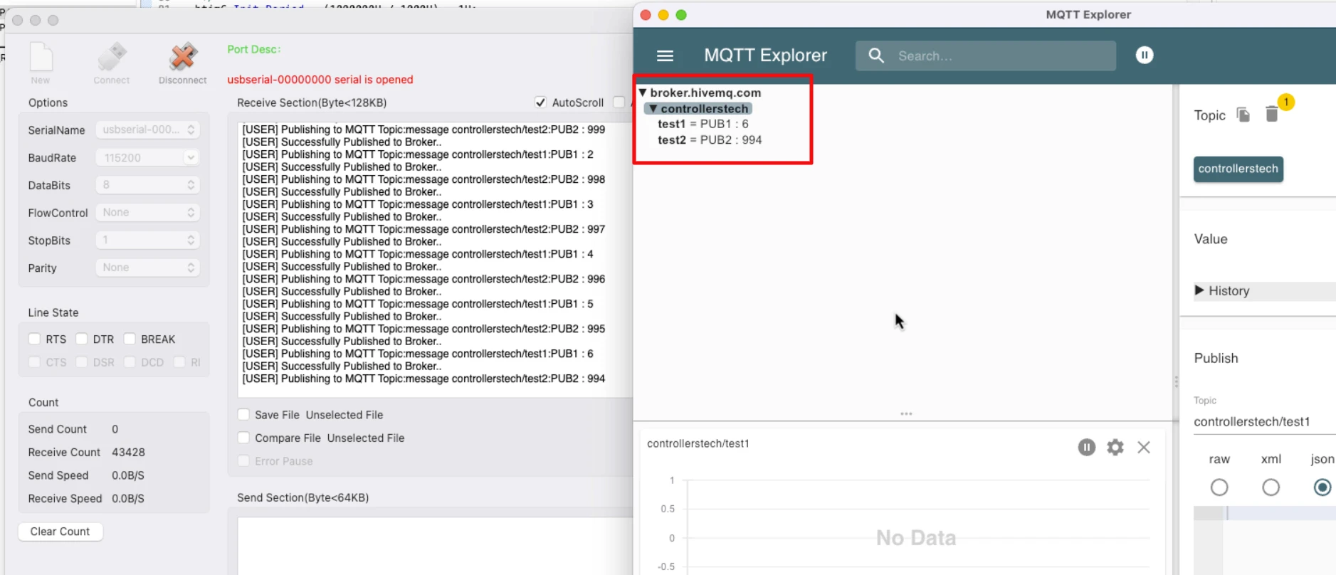
You can see that the MQTT Explorer is receiving the messages published to the topics by STM32 client. The value of the count variable from Task1 is increasing from 0 while the count variable from Task2 is reducing from 1000.
This indicates that the STM32 MQTT Client is publishing messages to two different topic successfully.
Receiving Data
The images below shows the data published by MQTT explorer to the topic controllerstech/led. The same data is received by the STM32 client and the LED is behaving as per the message.
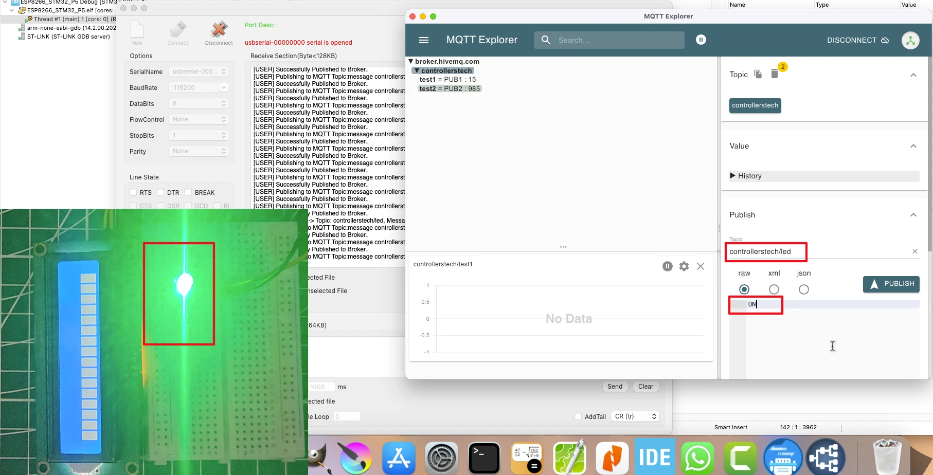
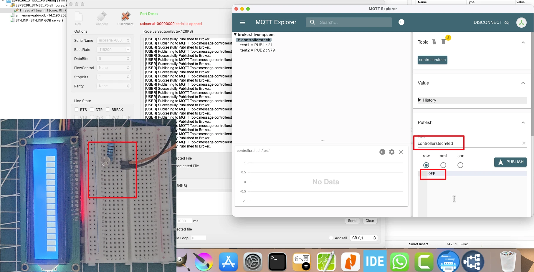
As shown the image first image, when the message “ON” is published by the MQTT Explorer, the LED connected to STM32 is turned on. Similarly, the second image shows when the message “OFF” is published by the client, the LED is turned Off.
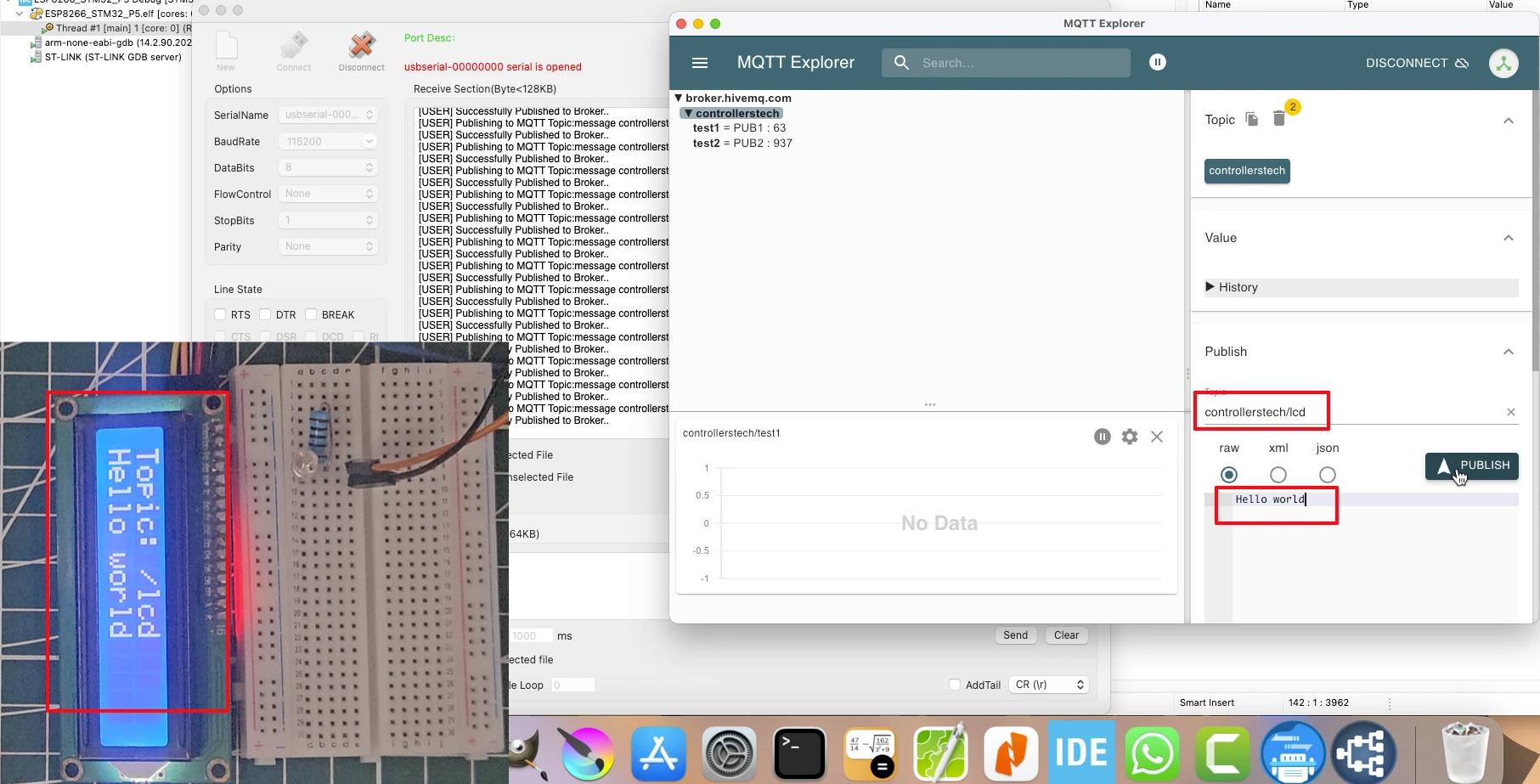
Similarly, when the MQTT Explorer publishes the message to the topic controllerstech/lcd, the data is printed on the LCD1602.
Video Tutorial
STM32 MQTT Subscription Video Tutorial
This guide explains how to subscribe to multiple MQTT topics. Along with the step-by-step written tutorial, I’ve also recorded a practical video walkthrough. Watch the video and follow the code.
Watch the STM32 MQTT TutorialConclusion
In this tutorial, we successfully implemented MQTT subscription on STM32 using the ESP8266 WiFi module, DMA, and FreeRTOS. By offloading data reception to DMA, the CPU workload was minimized, resulting in more efficient and reliable message handling. We also integrated an LCD1602 to display incoming MQTT messages and controlled an LED through subscribed topics, demonstrating a complete IoT workflow.
This approach lays the foundation for building scalable IoT systems where STM32 devices can handle multiple topics, react to commands, and display real-time feedback with minimal overhead. In the next steps, you can expand this project by experimenting with different QoS levels, subscribing to multiple topics simultaneously, or integrating sensors for more advanced applications.
Browse More STM32 IoT Tutorials
STM32 IoT with ESP8266 (Part 2): – Send Sensor Data to ThingSpeakCloud
STM32 IoT with ESP8266 (Part 3): MQTT Connect and Publish messages
STM32 IoT with ESP8266 (Part 4): Publish MQTT messages with RTOS
STM32 ESP8266 MQTT Project Download
STM32 ESP8266 MQTT FAQs
Subscribe
Login
0 Comments
Newest
