Last Updated: February 6, 2026
How to Interface R307 Fingerprint Module with STM32
The R307 fingerprint sensor module is a popular biometric device used for secure authentication in embedded systems. In this tutorial, we will learn how to interface the R307 fingerprint module with STM32 using UART communication. By connecting the sensor with the STM32 microcontroller, you can enroll, store, and verify fingerprints with reliable accuracy.
The combination of STM32 and the R307 sensor enables the development of practical applications such as smart door locks, attendance systems, and identity verification devices, where speed, security, and reliability are crucial. Since the R307 communicates over a serial UART interface, we will use the STM32’s UART peripheral to establish communication.
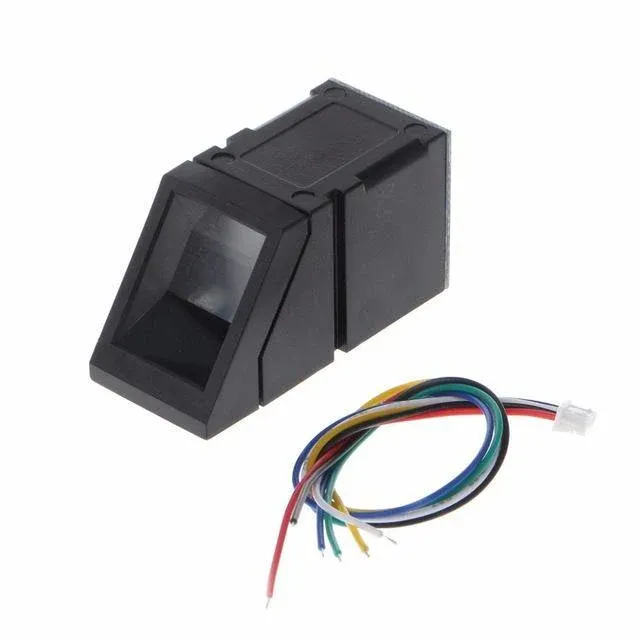
R307 Fingerprint Module Overview
The R307 Fingerprint Sensor Module is a popular biometric device that easily connects to microcontrollers and embedded systems. It provides a reliable way to capture, store, and match fingerprints for authentication purposes. The module uses UART communication, making it simple to connect with controllers like STM32, Arduino, or ESP32.
Key Features
- UART communication interface for easy integration with microcontrollers
- Supports both 1:1 (verification) and 1:N (identification) matching modes
- Onboard storage for fingerprint templates, reducing the need for external memory
- Compact design with built-in image processing and matching algorithms
Technical Specifications
- Operating Voltage: 3.6V to 6.0V (typically 3.3V or 5V compatible)
- Working Current: ~50 mA (typical), with low idle current
- Resolution: 500 dpi for accurate fingerprint capture
- Response Time: Less than 1 second for fingerprint recognition
- Template Capacity: Can store up to 1000 fingerprints (depending on the version)
Common Applications
- Attendance systems for schools, offices, and organizations
- Access control in secure areas, smart locks, and door entry systems
- Embedded IoT security for devices requiring biometric authentication
STM32 R307 Fingerprint Project Requirement
I am going to use the STM32F446 Dev board from WeAct Studio along with the R307s Fingerprint Sensor Module for this project. We’ve added affiliate links for your convenience — if you purchase through these links, it helps support our work at no extra cost to you.
- STM32F446 Dev Board
- R307s Fingerprint Sensor Module
- Jumper Wires
- Breadboard
Wiring R307 Fingerprint Module with STM32
Before we begin programming, we first need to establish the hardware connections between the R307 Fingerprint Sensor and the STM32 microcontroller. Since the R307 communicates using UART protocol, we will connect its TX and RX pins to the corresponding UART pins on STM32. Additionally, we will power the module with a 5V supply and use LED indicators to show the fingerprint status.
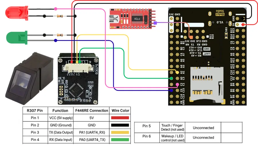
The wiring connections are as follows:
R307 to STM32 Connections
- Pin 1 (VCC) → 5V on STM32 (Red wire)
- Pin 2 (GND) → GND on STM32 (Black wire)
- Pin 3 (TX – Data Output) → PA1 (UART4_RX) on STM32 (Yellow wire)
- Pin 4 (RX – Data Input) → PA0 (UART4_TX) on STM32 (Green wire)
- Pin 5 (Touch/Finger Detect) → Not connected
- Pin 6 (Wakeup/LED Control) → Not connected
Additional Components
- Red LED connected to pin PC1 to indicate finger mismatch
- Green LED connected to pin PC0 to indicate finger match
- Both LEDs are connected with current-limiting resistors
FTDI Module
We use it to view user interaction logs on the serial console. Since we only send data from STM32 to the FTDI, we connect PA10 (UART1_TX) to the module’s RX pin.
STM32CubeMX Configuration
Let’s use STM32CubeMX to configure the UART peripheral for the fingerprint sensor and set up GPIO pins for the LEDs.
UART4 (R307) Configuration
Below is the image showing the UART4 configuration for R307 fingerprint module.
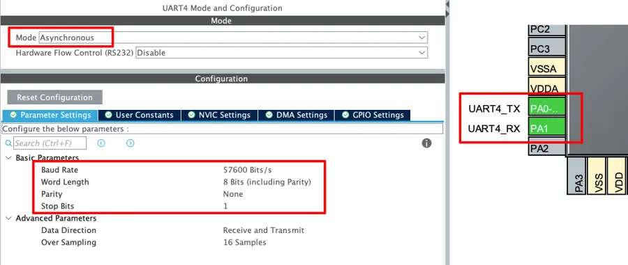
We configure UART4 in Asynchronous mode. Next, set the baud rate to 57600 bits/s with 8-bit word length, no parity, and 1 stop bit, as required for the fingerprint sensor to work. This will automatically configure PA0 and PA1 as UART4_TX and UART4_RX. Finally, connect these pins to the R307’s RX and TX pins, as shown in the wiring diagram.
UART1 (FTDI) Configuration
As mentioned earlier, UART1 sends the user interaction logs to the FT232, which then displays them on the serial console. The image below shows the UART1 configuration.
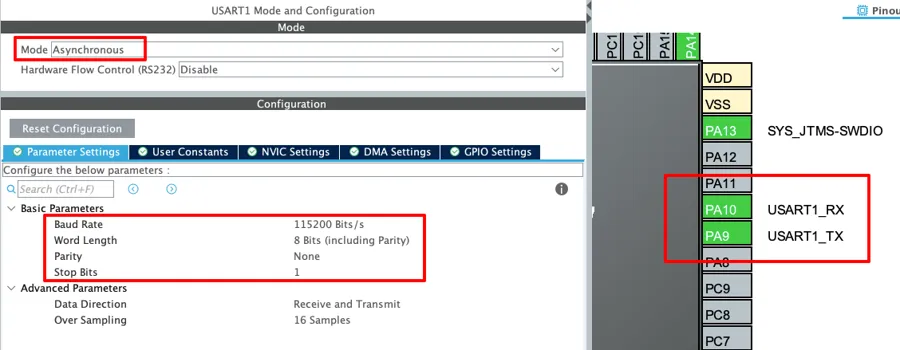
Configure the UART1 in the Asynchronous mode. Set the Baud rate to 115200 Bits/s with 8 Bits of word length, No parity and 1 Stop bit. You can configure this however we want, but this is an optimal configuration.
The pins PA9 and PA10 will configure as the UART1_TX and UART1_RX respectively. Because we only need to send data to the FTDI, we connect PA9 (UART1_TX) to the FTDI’s RX pin, as shown in the wiring diagram.
LED Configuration
We will use the LEDs to show whether a finger matches the database or not. The image below illustrates the pin configuration for the LEDs.
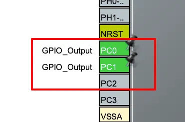
As shown in the wiring diagram, we connect the red LED to pin PC1 and the green LED to pin PC0. Then, we configure both pins as GPIO outputs, which we will control directly in the code.
Writing Code to Communicate with R307
Before writing the main code, we will first learn the command structure, how to send a command, and how to handle the response.
Understanding the Command and Response Packets
The image below shows a general command/data/response packet used by the R307.
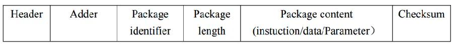
The description for the packet is shown in the table below.
| Field | Size (Bytes) | Description |
|---|---|---|
| Header | 2 | Fixed value 0xEF01 indicating start of packet |
| Address | 4 | Module address (default: 0xFFFFFFFF) |
| Package ID | 1 | Identifies type of packet: – 0x01 → Command – 0x02 → Data – 0x07 → Acknowledge – 0x08 → End of data |
| Package Length | 2 | Number of bytes in Package Content + 2 (checksum itself is excluded) |
| Package Content | N (varies) | Actual instruction, parameters, or returned data |
| Checksum | 2 | Sum of Package ID + Length + Content |
For example, if we want to send the command to verify the password, the command and response packets will be as shown in the images below.
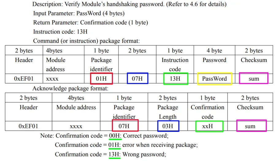
The command packet for verifying module’s password is as follows:
- Header (2 bytes): Always
0xEF01, start of packet. - Module Address (4 bytes): Default is
0xFFFFFFFF. - Package Identifier (1 byte):
0x01-> Command packet. - Package Length (2 bytes): 1B Instruction + 4B Password + 2B Checksum.
- Instruction Code (1 byte):
0x13-> Verify Password command. - Password (4 bytes): The password we send for verification (default:
0x00000000). - Checksum (2 bytes): Sum of Package Identifier + Length + Content.
Example: EF01 FFFFFFFF 01 0007 13 00000000 XXXX
The Response packet sent by the R307 for this command is as follows:
- Header (2 bytes):
0xEF01. - Module Address (4 bytes): Same as sent.
- Package Identifier (1 byte):
0x07-> Acknowledge packet. - Package Length (2 bytes): 1B Confirmation Code + 2B Checksum.
- Confirmation Code (1 byte): Shows the result.
00H→ Correct password01H→ Error receiving command package13H→ Wrong password
- Checksum (2 bytes): Same rule as command.
Example: EF01 FFFFFFFF 07 0003 00 XXXX (means password is correct).
How to build the command to be sent
We need to build the command before transmitting it over the UART. We will write a common function to build all types of commands. This function R307_BuildCommand creates a valid command packet that can be sent to the R307 fingerprint sensor.
static uint16_t R307_BuildCommand(uint8_t *out_buf, uint8_t instruction,
                                  const uint8_t *params, uint16_t params_len)
{
    uint16_t idx = 0;

    // Header + address
    out_buf[idx++] = 0xEF;
    out_buf[idx++] = 0x01;
    out_buf[idx++] = 0xFF;
    out_buf[idx++] = 0xFF;
    out_buf[idx++] = 0xFF;
    out_buf[idx++] = 0xFF;

    // Packet identifier: command packet
    out_buf[idx++] = 0x01;

    // Length = Instruction(1) + params_len + checksum(2)
    uint16_t length_field = 1 + params_len + 2;
    out_buf[idx++] = (length_field >> 8) & 0xFF;
    out_buf[idx++] = length_field & 0xFF;

    // Instruction
    out_buf[idx++] = instruction;

    // Params
    if (params_len && params != NULL) {
        memcpy(&out_buf[idx], params, params_len);
        idx += params_len;
    }

    // Compute checksum: sum of bytes from packet identifier (index 6) to last data byte
    uint16_t sum = 0;
    for (uint16_t i = 6; i < idx; ++i) sum += out_buf[i];

    // Append checksum (2 bytes)
    out_buf[idx++] = (sum >> 8) & 0xFF;
    out_buf[idx++] = sum & 0xFF;

    return idx;
}Here’s what happens step by step:
- Start with header and address
It always begins with:EF01→ fixed start codeFFFFFFFF→ default sensor address
- Add packet identifier
0x01means this is a command packet. - Add length field
Length = Instruction byte (1) + Parameters length + Checksum (2).
This tells the sensor how many bytes are coming after this field. - Add instruction
This is the command code (like “enroll finger” or “delete template”). - Add parameters (if any)
If extra data is needed for the command, copy it here. - Compute checksum
Add up all bytes starting from packet identifier (0x01) up to the last parameter. - Append checksum (2 bytes)
The checksum ensures data integrity, so the sensor knows if the command was corrupted. - Return total length
Finally, the function returns the number of bytes written inout_buf.
How to Send Command and Check Response
Below is function to send the command to the device and check the response sent by the device.
static HAL_StatusTypeDef R307_SendCommand(uint8_t *cmd, uint16_t cmd_len,
                                   uint8_t *response, uint16_t response_max_len)
{
    HAL_StatusTypeDef status;

    // Transmit full command
    status = HAL_UART_Transmit(&R307_UART, cmd, cmd_len, 500);
    if (status != HAL_OK) {
    	DB_LOG("UART transmit failed");
        return status;
    }

    // Receive header (9 bytes): EF01 + Addr(4) + PID + LEN_H + LEN_L
    status = HAL_UART_Receive(&R307_UART, response, 9, 1000);
    if (status != HAL_OK) {
    	DB_LOG("UART receive failed (header)");
        return status;
    }

    // Get length field (this length already includes checksum)
    uint16_t payload_len = ((uint16_t)response[7] << 8) | response[8];
    uint16_t total_len = 9 + payload_len; // header + payload_len (payload includes checksum)

    if (total_len > response_max_len) {
    	DB_LOG("Response too large (%d bytes, buffer max %d)", total_len, response_max_len);
        // Drain remaining bytes if needed? For now return error
        return HAL_ERROR;
    }

    // Read rest of packet (payload_len bytes)
    if (payload_len > 0) {
        status = HAL_UART_Receive(&R307_UART, &response[9], payload_len, 1000);
        if (status != HAL_OK) {
        	DB_LOG("UART receive failed (payload)");
            return status;
        }
    }

    return HAL_OK;
}This function R307_SendCommand is used to send a command to the R307 fingerprint sensor and then receive its reply over UART.
Here’s what happens step by step:
- Send the command
It first sends the full command (given incmdwith lengthcmd_len) through UART. - Receive the header (first 9 bytes of reply)
The fingerprint sensor always replies with a packet. The first 9 bytes of this reply are always the same (lengthwise):EF01→ start codeAddr(4)→ sensor addressPID→ packet identifierLEN_H + LEN_L→ total length of the rest of the packet
- Check how long the rest of the packet is
From the header, it extracts the payload length (number of bytes to follow, including checksum). - Receive the payload
If payload length > 0, it reads the remaining bytes of the packet. - Return success
If everything went fine, it returnsHAL_OK.
Fingerprint Enrolment Process
We will write a separate function to Enroll the fingerprint to the sensor.
HAL_StatusTypeDef R307_Enroll(uint16_t page_id)
{
    FP_LOG("\r\n=== ENROLL FINGERPRINT ===");
    FP_LOG("Target ID = %d", page_id);

    // 1st capture
    FP_LOG("Place your finger...");
    if (WaitForFingerPlacement(20000) != HAL_OK) {
    	return HAL_TIMEOUT;
    }

    FP_LOG("Capturing finger...");
    while (R307_CaptureFinger() != HAL_OK) {
        HAL_Delay(200); // wait and retry
    }
    if (R307_Image2Tz(1) != HAL_OK) {
        FP_LOG("Failed to convert first image");
        return HAL_ERROR;
    }
    FP_LOG("First image captured and converted");

    // Wait until finger is removed (with timeout)
    FP_LOG("Please remove your finger...");

    if (WaitForFingerRemoval(10000) != HAL_OK) {
        return HAL_TIMEOUT;
    }

    // 2nd capture
    FP_LOG("Place the same finger again...");
    if (WaitForFingerPlacement(20000) != HAL_OK) {
    	return HAL_TIMEOUT;
    }

    FP_LOG("Capturing finger again...");
    while (R307_CaptureFinger() != HAL_OK) {
        HAL_Delay(200); // wait and retry
    }

    if (R307_Image2Tz(2) != HAL_OK) {
        FP_LOG("Failed to convert second image");
        return HAL_ERROR;
    }
    FP_LOG("Second image captured and converted");

    FP_LOG("Please remove your finger...");

       if (WaitForFingerRemoval(10000) != HAL_OK) {
           return HAL_TIMEOUT;
       }

    // Merge buffers into template
    if (R307_GenerateTemplate() != HAL_OK) {
        FP_LOG("Failed to generate template (merge)");
        return HAL_ERROR;
    }
    FP_LOG("Template merged");

    // Store model at page_id (store from buffer 1)
    if (R307_StoreTemplate(1, page_id) != HAL_OK) {
        FP_LOG("Failed to store template");
        return HAL_ERROR;
    }

    FP_LOG("Enroll successful. Stored at ID=%d", page_id);
    return HAL_OK;
}The function asks the user to place and remove the same finger twice, converts both images into data, merges them into a fingerprint template, and then stores it in the sensor’s database at the given ID.
Here’s what happens step by step:
- Start enrollment
It prints messages to the log, showing the target ID where the fingerprint will be stored. - First capture
- Waits until the finger is detected.
- Captures the fingerprint image.
- Converts the image into data and saves it into buffer 1.
- Ask to remove finger
Waits until the finger is lifted (with timeout). - Second capture
- Waits until the finger is detected.
- Captures the image again.
- Converts it into data and saves it into buffer 2.
- Ask to remove finger again
Waits until the finger is lifted. - Generate template
- Combines the two captured images (buffer 1 and buffer 2).
- Creates a final fingerprint template.
- Store template
- Saves the generated template into sensor memory at the given
page_id. - If this works, enrollment is complete.
- Saves the generated template into sensor memory at the given
- Success
Prints confirmation that the fingerprint has been stored successfully.
Fingerprint Verification & Matching
Here we will check the finger against all stored IDs to find a match. Below is the function to verify the finger.
HAL_StatusTypeDef R307_Verify(uint16_t *out_page_id, uint16_t *out_score)
{
	HAL_StatusTypeDef status;

    FP_LOG("\r\n=== VERIFY FINGERPRINT ===");
    FP_LOG("Place your finger...");
    if (WaitForFingerPlacement(20000) != HAL_OK) {
    	return HAL_TIMEOUT;
    }

    FP_LOG("Capturing finger...");
    while (R307_CaptureFinger() != HAL_OK) {
        HAL_Delay(200); // wait and retry
    }
    if (R307_Image2Tz(1) != HAL_OK) return HAL_ERROR;

    // Search entire library; change range if you have different capacity
    uint16_t page_id = 0, score = 0;
    FP_LOG("Searching Database...");
    if (R307_SearchDatabase(&page_id, &score, 0x0000, 0x03E8) == HAL_OK) {
        FP_LOG("Match found: ID=%d Score=%d", page_id, score);
        if (out_page_id) *out_page_id = page_id;
        if (out_score)   *out_score   = score;
        status = HAL_OK;
    }
    else {
    	status = HAL_ERROR;
    }

    FP_LOG("Please remove your finger...");

       if (WaitForFingerRemoval(10000) != HAL_OK) {
           status = HAL_TIMEOUT;
       }
    return status;
}This function captures a finger, searches the stored database, and then shows whether it found a match, along with the finger’s ID and score.
Here’s what happens step by step:
- Start verification
Shows a log message and asks the user to place their finger. - Capture fingerprint
- Waits until finger is detected.
- Captures the fingerprint image.
- Converts it into data (stored in buffer 1).
- Search database
- Compares the captured fingerprint with all stored templates (from ID
0x0000to0x03E8, i.e., up to 1000 IDs). - If a match is found -> returns the
page_id(location in database) andscore(how close the match is). - If no match -> returns error.
- Compares the captured fingerprint with all stored templates (from ID
- Remove finger
Waits until the user lifts the finger before finishing. - Return result
- Returns
HAL_OKif match found. - Returns
HAL_ERRORif no match. - Returns
HAL_TIMEOUTif user didn’t place/remove finger in time.
- Returns
STM32 R307 main function
Inside the main function, we will clear memory and enrolls all fingerprints on the first run. After that, it will keep running in a loop, verifying any finger placed and showing green for success or red for failure.
int main(void)
{
	.....
	.....

  if (R307_VerifyPassword(0x00000000) != HAL_OK) {
      FP_LOG("Password verify failed!");
      Error_Handler();
  }

  if (HAL_RTCEx_BKUPRead(&hrtc, RTC_BKP_DR0) != 0x9876){
	  FP_LOG("Clearing All Fingerprints");
	  if (R307_ClearAllFingerprints() != HAL_OK){
		  FP_LOG("Failed to clear All Fingerprints");
		  Error_Handler();
	  }
	  FP_LOG("All Fingerprints Removed");
	  for (int i=1; i<=NUM_FINGERS; i++)
	  {
		  HAL_StatusTypeDef status;
		  int numRetries = 3;

		  do
		  {
			  FP_LOG("\n\nPlace your finger to enroll at ID %d", i);
			  status = R307_Enroll(i);
		  }
		  while ((status != HAL_OK) && (numRetries-- > 0));
		  if (status != HAL_OK)
			  FP_LOG("Enrollment failed for ID %d after 3 attempts", i);
	  }
	  HAL_RTCEx_BKUPWrite(&hrtc, RTC_BKP_DR0, 0x9876);
  }

  while (1)
  {
	  uint16_t matched_id, score;
	  FP_LOG("\n\nPlace finger to verify...");
	  HAL_StatusTypeDef status = R307_Verify(&matched_id, &score);
	  if (status == HAL_ERROR) {
	      FP_LOG("No match found.");
	      HAL_GPIO_WritePin(RED_PORT, RED_PIN, 1);
	  }
	  else if (status == HAL_OK) {
		  HAL_GPIO_WritePin(GREEN_PORT, GREEN_PIN, 1);
	  }
	  HAL_Delay(2000);
	  HAL_GPIO_WritePin(GREEN_PORT, GREEN_PIN, 0);
	  HAL_GPIO_WritePin(RED_PORT, RED_PIN, 0);
  }
}Here’s what happens step by step:
- Verify sensor password
- Sends a default password (
0x00000000) to check communication with the fingerprint sensor. - If it fails you can send command to set the password for the sensor and then verify the password again.
- Sends a default password (
- Check if enrollment is needed
- Reads a backup register in RTC (
RTC_BKP_DR0). - If it’s not set to
0x9876, it means enrollment hasn’t been done before.
- Reads a backup register in RTC (
- Clear all old fingerprints
- Deletes all stored templates from sensor memory.
- Deletes all stored templates from sensor memory.
- Enroll new fingerprints
- For each ID from
1toNUM_FINGERS, it asks the user to place a finger. - Calls
R307_Enroll(i)to capture and store that finger at IDi. - If enrollment fails, it retries up to 3 times.
- Once all are done, it writes
0x9876into RTC backup so next reset it won’t re-enroll.
- For each ID from
- Loop forever (verification mode)
- Waits for a finger to be placed.
- Runs
R307_Verifyto check if it matches any stored ID. - If match found, turns Green LED ON.
- If no match, turns Red LED ON.
- Waits 2 seconds, then turns LEDs off.
Result of R307 interfaced with STM32
Below is the short video showing the working of the above code.
As you can see in the video, I first enrolled the right thumb and right index finger. Then, the green light turned on when I placed the correct finger on the sensor. Whereas, the red light turned on when I placed the left thumb or left index finger.
The logs on the console guides user about what to do. It asks user to place the finger on the sensor or remove the finger from it.
Video Tutorial
R307 Fingerprint Module Video Tutorial
While the written guide below provides all the details and code for reference, sometimes a visual demonstration can make all the difference. I’ve created a complete video walkthrough that runs through the entire process in real-time. Follow the written steps here while watching the implementation in the video to solidify your understanding and catch any subtle details
Watch the VideoConclusion
In this tutorial, we covered how to interface the R307 fingerprint module with an STM32 microcontroller using UART communication. We discussed the hardware connections, UART configuration, and the command sequence required to enroll and verify fingerprints. The post also demonstrated how the STM32 communicates with the R307 module to store fingerprint templates and perform matching reliably.
This setup is very useful for adding biometric authentication to embedded projects. It allows you to build secure systems such as door locks, attendance machines, and access control devices with ease. The combination of the R307 module and STM32 offers good performance, flexibility, and low cost, making it a practical choice for real-world fingerprint-based applications.
