Published: December 17, 2025
Last Updated: February 5, 2026
Last Updated: February 5, 2026
FreeRTOS Queues on Arduino (Inter Task Communication)
FreeRTOS allows your Arduino to run multiple tasks at the same time, where each task can perform a different job. One task may read a sensor, while another task controls an LED or sends data to the Serial Monitor. However, tasks cannot work in isolation.
They often need to share data with each other in a safe and reliable way. This is where FreeRTOS queues on Arduino become very useful.
A queue provides a structured method for tasks to exchange data, ensuring that information is transferred in the correct order and without corruption. In this tutorial, we will use FreeRTOS queues to pass ADC values between tasks, a technique that is widely used in real-world embedded systems.
What Are FreeRTOS Queues and Why We Use Them
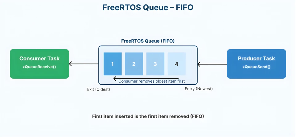
A FreeRTOS queue is a FIFO (First In, First Out) buffer. Tasks can send data to the queue. Other tasks can receive data from it. FreeRTOS handles all synchronization internally. You do not need to worry about locks or race conditions.
Why Task-to-Task Communication Is Important
In a multitasking system, tasks rarely work alone.
For example:
- One task reads ADC data from a potentiometer
- Another task controls LED brightness
- A third task prints values to Serial Monitor
These tasks must share information. Without proper communication, tasks may read invalid data. This can cause unstable behavior and hard-to-find bugs.
FreeRTOS queues solve this problem by providing controlled data transfer between tasks.
Why Use Queues Instead of Global Variables
Using global variables looks easy at first, but it creates serious problems in a FreeRTOS system.
- Multiple tasks can access the same variable at the same time
- Data may change while another task is reading it
- Race conditions can occur
Queues avoid all these issues. They ensure:
- Only one task accesses data at a time
- Data is transferred in the correct order
- Tasks can block and wait safely
How FreeRTOS Queues Work Internally
To use FreeRTOS queues effectively, it is important to understand how they work internally.
A queue is a fixed-size buffer managed by the FreeRTOS kernel. Each queue stores data in FIFO order, which means the first value sent is the first value received. FreeRTOS also takes care of task synchronization, so multiple tasks can use the same queue safely.
Queue Length and Item Size Explained
When creating a FreeRTOS queue, two important parameters must be defined.
- Queue length
This defines how many items the queue can hold at one time. - Item size
This defines the size of each data item stored in the queue.
For example, when you create a queue like this:
xQueueCreate(5, sizeof(int));The queue can store 5 integer values. All items in a queue must be the same size. This makes memory usage predictable and efficient, which is very important on Arduino boards with limited RAM.
If the queue becomes full, FreeRTOS can block the sending task or return immediately, depending on how it is configured.
Blocking Read and Blocking Write in Queues
One powerful feature of FreeRTOS queues is blocking behavior. Blocking means a task can wait until a condition is met instead of running continuously.
- Blocking write
If a task tries to send data to a full queue, it can wait until space becomes available. - Blocking read
If a task tries to read from an empty queue, it can wait until new data arrives.
Example snippet for a blocking read:
xQueueReceive(adcQueue, &adcValue, pdMS_TO_TICKS(100));In this case, the task waits for up to 100 milliseconds for data to arrive in the queue. Blocking reduces CPU usage. It also makes the system more efficient and responsive.
Alternatively, you can use portMAX_DELAY to make the task wait forever for the data.
Queue Performance on Memory-Limited Arduino
Arduino AVR boards like Arduino Uno, Nano, and Mega have very limited RAM. For example, the Arduino Uno has only 2 KB of SRAM. Because of this, queue usage must be planned carefully.
FreeRTOS queues are powerful, but they are not free. They consume memory and CPU time. Understanding this helps you write efficient FreeRTOS Arduino applications.
RAM Usage and Queue Overhead
Each FreeRTOS queue uses RAM in two ways:
- First, FreeRTOS allocates memory for the queue control structure. This structure stores information like queue length, item size, and task waiting lists.
- Second, it allocates memory for the actual data buffer. This buffer holds all the items stored in the queue.
For example:
- A queue of 10 integers uses much more RAM than a queue of 5 bytes
- Large data types increase memory usage quickly
On AVR-based Arduino boards, even a few extra bytes matter.
Best practices for AVR:
- Use the smallest data type possible
- Keep queue length short
- Avoid storing large structures in queues
When Not to Use Queues in FreeRTOS
Queues are very useful, but they are not always the best solution. Avoid using queues when:
- Data is generated at very high frequency
- Only a simple signal or flag is needed
- Very fast response is required
For example, sending ADC values at extremely high speed through a queue can overload the system. In such cases, better alternatives are:
- Task notifications for fast signaling
- Event groups for state-based communication
Choosing the right communication method improves performance and reduces RAM usage. This is especially important when working with FreeRTOS on memory-limited Arduino AVR boards.
Hands-On: FreeRTOS Queue Example with ADC on Arduino
Now let’s move to a practical FreeRTOS queue example on Arduino. This hands-on demo will clearly show how task-to-task communication works using queues.
We will use two tasks:
- One task reads ADC values from a potentiometer
- Another task receives those values from a queue and processes them
Example Overview and Hardware Setup
In this example, we read a potentiometer connected to the Arduino. The ADC value is sent to a FreeRTOS queue.
Another task receives the value and:
- Prints it on the Serial Monitor
- Uses it later to control LED brightness
Connections:
The image below shows the connection between Potentiometer, LED and Arduino.
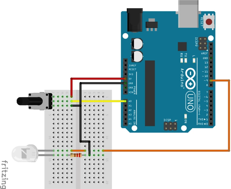
Connect the components as follows:
- Potentiometer middle pin -> A0
- LED -> PWM pin 9
Creating a Queue for ADC Values
First, we need a queue to store ADC readings. We declare a queue handle globally so both tasks can access it.
QueueHandle_t adcQueue;Then we create the queue inside setup().
adcQueue = xQueueCreate(5, sizeof(int));This means:
- The queue can store 5 ADC values
- Each value is of type
int
This is enough for smooth communication without wasting RAM.
Task 1: Reading ADC and Sending Data to Queue
The first task reads the ADC value continuously. After reading, it sends the value to the queue.
Short code snippet:
int adcValue = analogRead(A0);
xQueueSend(adcQueue, &adcValue, portMAX_DELAY);Here:
analogRead()gets the potentiometer valuexQueueSend()places the value into the queueportMAX_DELAYblocks the task if the queue is full
Task 2: Receiving Queue Data and Processing It
The second task waits for data from the queue. Once data is received, it processes the value.
Short snippet:
if (xQueueReceive(adcQueue, &receivedValue, pdMS_TO_TICKS(200)))
{
  int pwmValue = map(receivedValue, 0, 1023, 0, 255);
  analogWrite(9, pwmValue);
  Serial.println(receivedValue);
}If data is available:
- The value is copied safely
- The PWM duty cycle updates, and the LED brightness changes smoothly
- The task prints it on the Serial Monitor
This task does not read the ADC directly. It depends completely on the queue for data.
The ADC value received from the queue ranges from 0 to 1023. But PWM output requires a value between 0 and 255. So we map the ADC value before driving the LED.
Adding Timeout to Queue Read
Using a timeout is a good practice. A timeout prevents the task from blocking forever if no data arrives.
In this example:
- The task waits for 200 milliseconds
- If no data arrives, it continues running normally
This keeps the system responsive. It also allows the task to perform other actions if needed.
Complete FreeRTOS Queue Example Code
Now that we have covered the theory, let’s put everything together. The code below shows a complete FreeRTOS queue example on Arduino.
This example includes:
- A queue for ADC values
- One task to read the potentiometer
- One task to receive data from the queue
- LED brightness control using PWM
- Serial Monitor output for debugging
#include <Arduino_FreeRTOS.h>
#include <queue.h>
QueueHandle_t adcQueue;
void TaskReadADC(void *pvParameters);
void TaskProcessADC(void *pvParameters);
void setup()
{
Serial.begin(9600);
pinMode(A0, INPUT);
pinMode(9, OUTPUT);
// Create a queue to hold 5 integer ADC values
adcQueue = xQueueCreate(5, sizeof(int));
if (adcQueue != NULL)
{
xTaskCreate(TaskReadADC, "ADC Read Task", 128, NULL, 1, NULL);
xTaskCreate(TaskProcessADC, "ADC Process Task", 128, NULL, 1, NULL);
}
}
void loop()
{
// Empty loop. FreeRTOS scheduler is running.
}
void TaskReadADC(void *pvParameters)
{
int adcValue;
while (1)
{
adcValue = analogRead(A0);
// Send ADC value to the queue
xQueueSend(adcQueue, &adcValue, portMAX_DELAY);
vTaskDelay(pdMS_TO_TICKS(100));
}
}
void TaskProcessADC(void *pvParameters)
{
int receivedValue;
while (1)
{
// Wait up to 200 ms for data from the queue
if (xQueueReceive(adcQueue, &receivedValue, pdMS_TO_TICKS(200)))
{
  int pwmValue = map(receivedValue, 0, 1023, 0, 255);
  analogWrite(9, pwmValue);
  Serial.println(receivedValue);
}
}
}This example is a strong foundation for more advanced FreeRTOS concepts. You can extend it by:
- Adding more producer or consumer tasks
- Sending structures instead of integers
- Replacing queues with task notifications
Output
The video below shows the Serial Monitor printing changing ADC values while the LED brightness increases and decreases smoothly as the potentiometer is rotated.
This confirms:
- The queue is working correctly
- Task-to-task communication is stable
- FreeRTOS queue handling on Arduino is reliable
Conclusion
In this tutorial, we explored FreeRTOS queues on Arduino and learned how they enable safe and reliable task-to-task communication. We discussed why queues are important, how they work internally, and how memory limitations on AVR boards affect their usage. Through a hands-on example, we saw how ADC values can be passed between tasks using a queue and then used to control LED brightness while also printing debug data to the Serial Monitor.
FreeRTOS queues are extremely useful in real embedded systems. They help you avoid race conditions, reduce bugs, and keep your code clean and modular. By using queues instead of global variables, tasks can exchange data in a structured way without interfering with each other. This makes your FreeRTOS-based Arduino projects more stable, scalable, and easier to maintain.
In the next part of this series, we will move beyond data transfer and focus on synchronization techniques in FreeRTOS. We will cover semaphores and mutexes, understand the difference between them, and learn when to use each one in practical Arduino examples.
Browse More Arduino FreeRTOS Tutorials
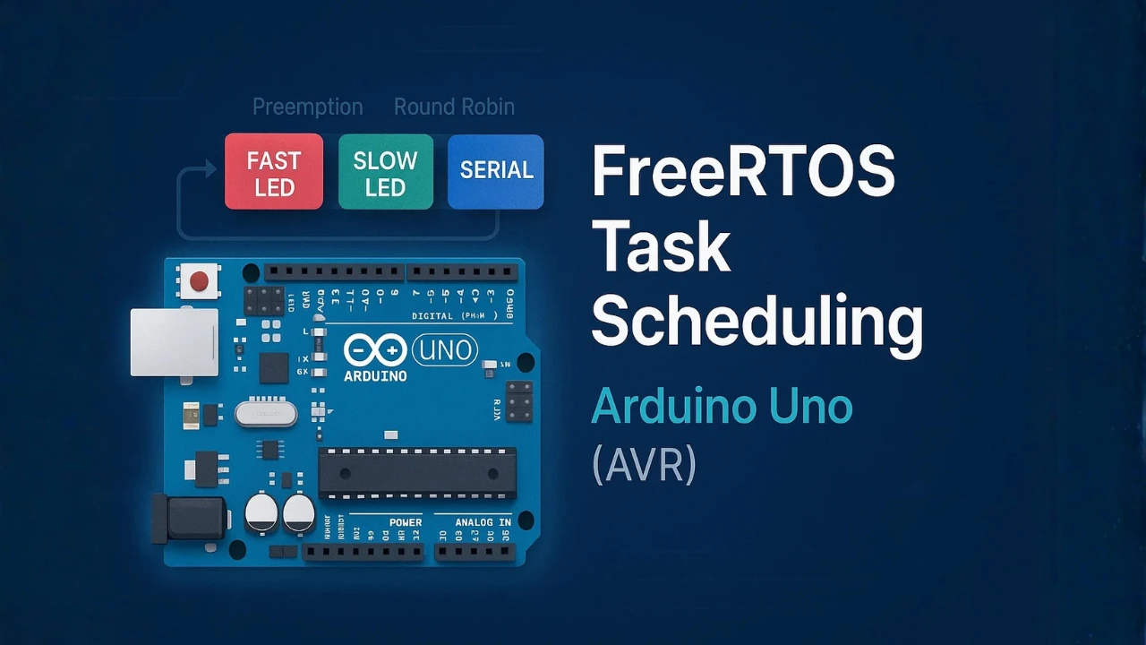
FreeRTOS on Arduino (Part 2): Task Scheduling on Arduino – Tasks, Priorities & Time Slicing
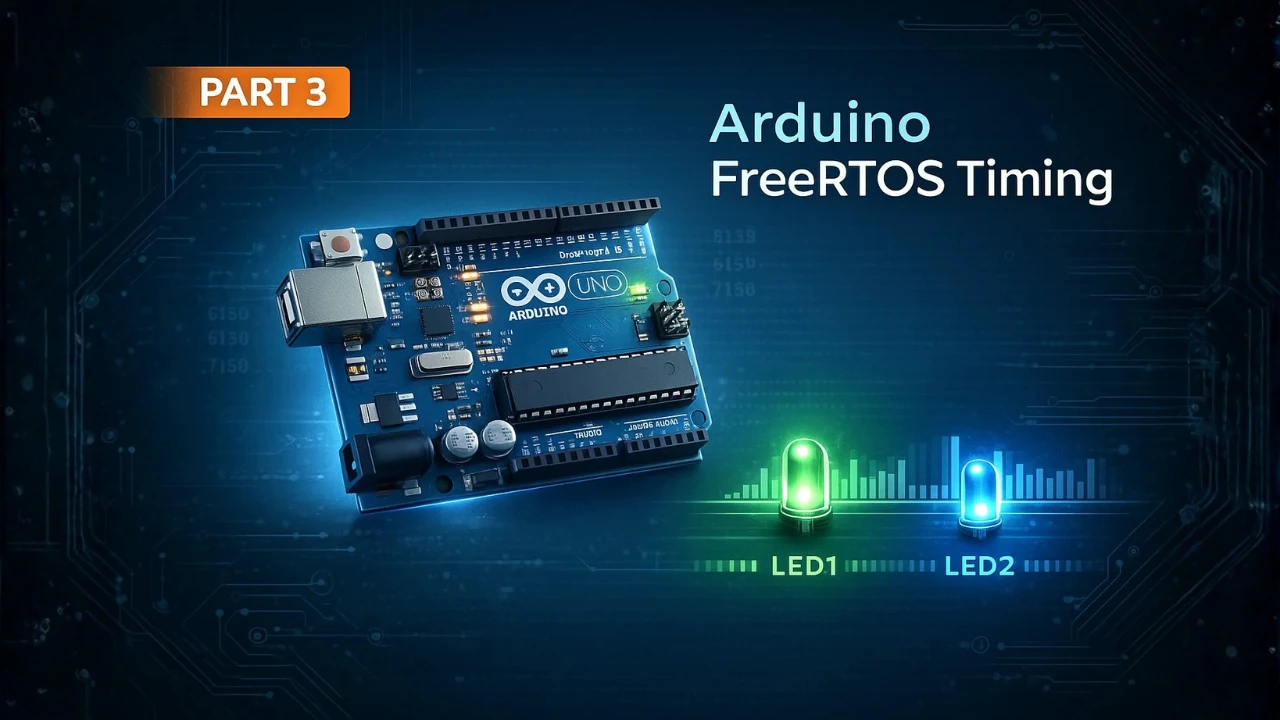
FreeRTOS on Arduino (Part 3): vTaskDelay vs vTaskDelayUntil and Software Timers
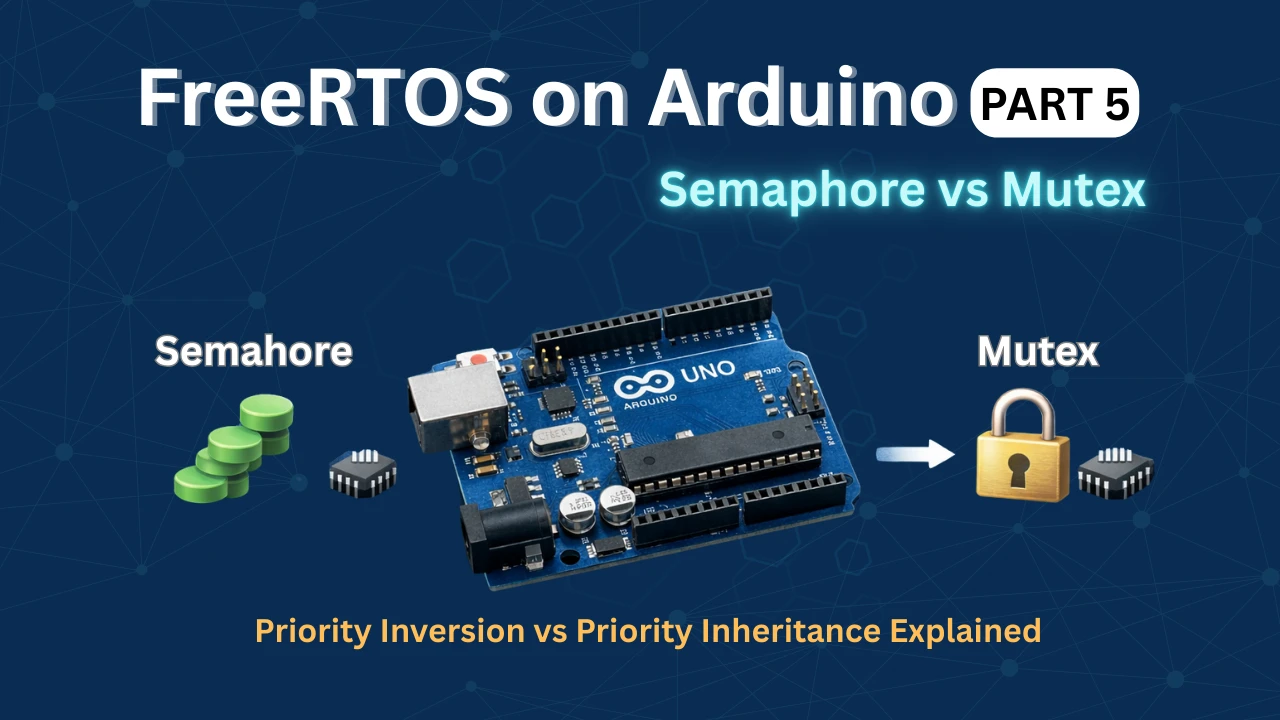
FreeRTOS on Arduino (Part 5): Semaphores and Mutex Explained with Practical Examples
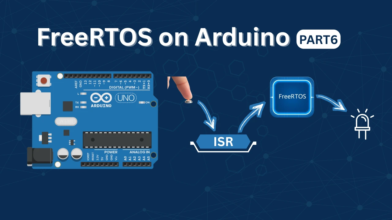
FreeRTOS on Arduino (Part 6): Using Interrupts in FreeRTOS
FreeRTOS Tutorial on Arduino (Part 7): Event Groups | Multi-Event Synchronization
Arduino FreeRTOS Project Download
FAQs – FreeRTOS Queues on Arduino
Subscribe
Login
0 Comments
Newest
