Home ▸ STM32 Tutorials ▸ STM32 LVGL ▸
Published: July 26, 2025
Last Updated: March 23, 2026
Last Updated: March 23, 2026
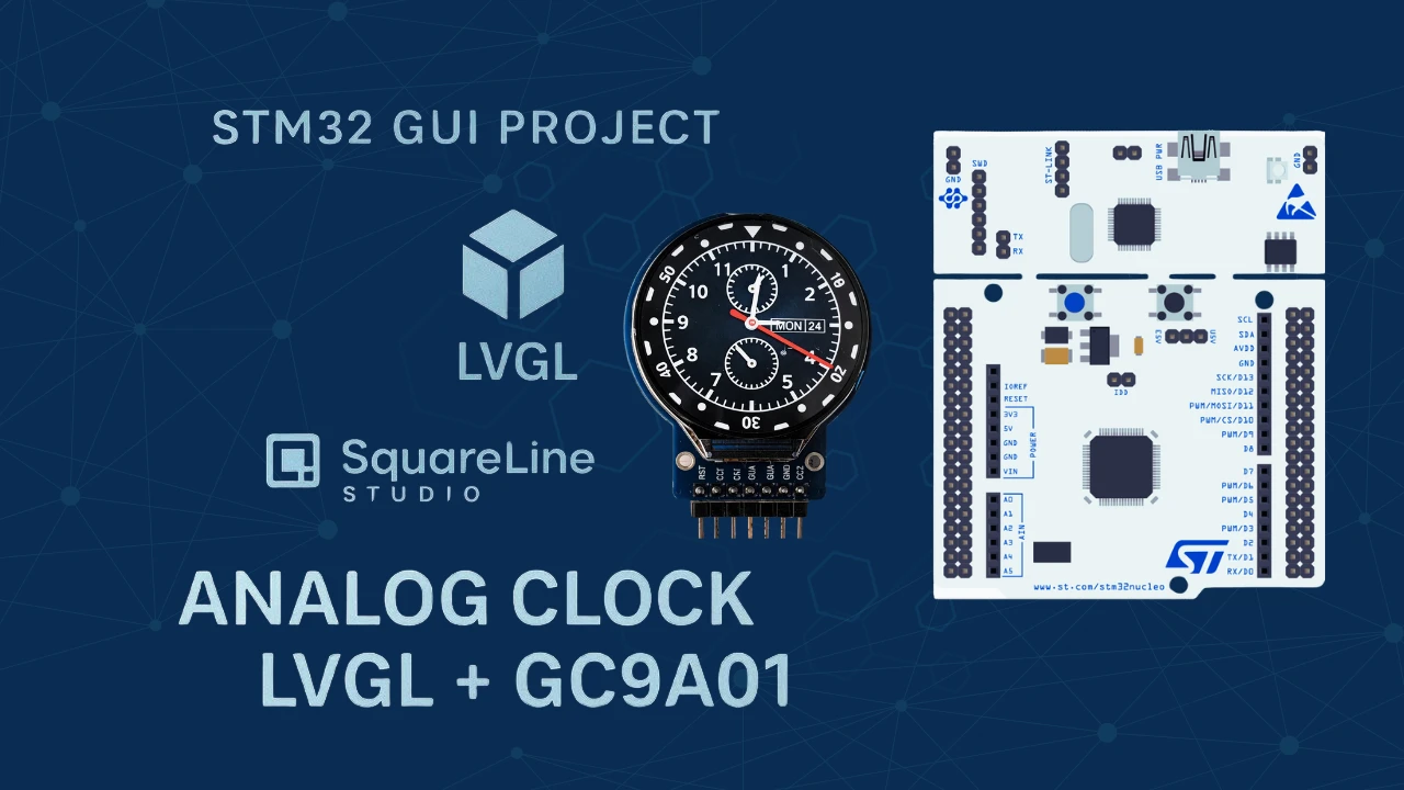
Display Analog Clock on GC9A01 Using STM32 and LVGL
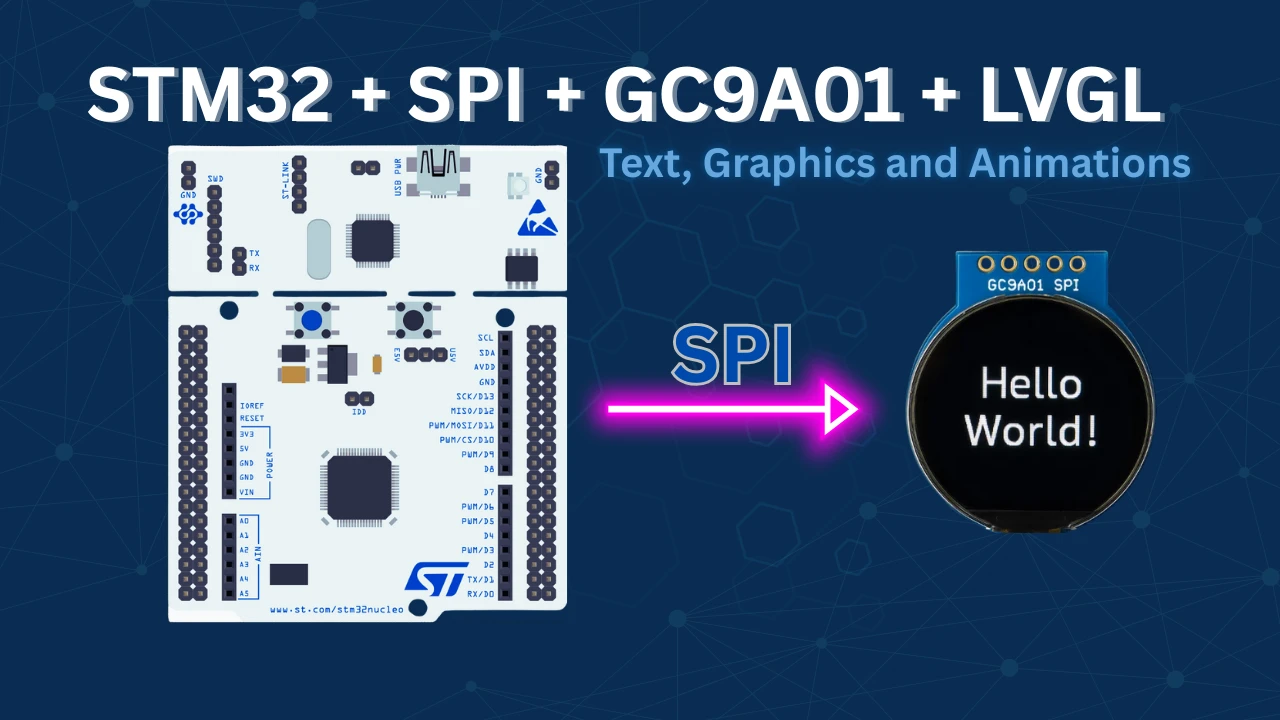
In Part 1, we learned how to connect the GC9A01 round TFT display to an STM32 using SPI and integrate it with LVGL v9.2 for GUI development. The tutorial covered wiring, STM32CubeMX setup for SPI and DMA, adding the GC9A01 driver, and configuring LVGL with partial frame buffers and a flush callback to update the display. A simple LVGL animation was tested successfully, confirming proper display and color rendering.
With this setup in place, Part 2 will take the project further by designing a custom analog watchface UI. We will use STM32CubeIDE for development, LVGL for the graphics framework, and Squareline Studio to create and import the user interface elements. The STM32 RTC will be integrated to provide accurate real-time clock updates, ensuring that the watchface displays the correct time dynamically.
Recommended Resources:
Introducing Squareline Studio
SquareLine Studio is a modern and intuitive GUI design tool built specifically for creating user interfaces that work seamlessly with LVGL (Light and Versatile Graphics Library). It allows developers and designers to visually build complex interfaces without manually writing code for every element. With its drag-and-drop design approach, SquareLine Studio greatly simplifies the UI creation process, making it easier and faster to develop visually appealing and functional interfaces for embedded devices.
Benefits: One of the biggest advantages of SquareLine Studio is its drag-and-drop GUI design, which allows quick prototyping and layout adjustments. It also provides easy integration with LVGL, automatically generating LVGL-compatible code that can be directly imported into projects developed in STM32CubeIDE or other IDEs.
Why it fits well with circular displays like GC9A01: SquareLine Studio offers flexible layouts, scalable widgets, and a pixel-perfect preview of the UI, making it ideal for round displays such as the GC9A01. Its ability to precisely position elements and adapt designs for circular screens ensures smooth integration without distortion or alignment issues.
Features of SquareLine Studio:
- Drag-and-drop widget placement – Easily create buttons, sliders, gauges, and other UI elements with minimal effort.
- Real-time preview – Instantly see how the interface will look and behave on the target display.
- Seamless LVGL code export – Automatically generates clean, ready-to-use LVGL code for embedded projects.
- Multi-resolution and screen adaptation – Design for different display sizes, including circular and rectangular screens, with consistent results.
Project Requirements
Below is the list of hardware and software components used in this project.
- WeAct Studio STM32H5-based custom development board
- 1.28 Inch GC9A01 Round TFT LCD Display Module
- STM32CUBEIDE
- LVGL 9.2
- Squareline Studio
Designing the Analog Clock in SquareLine Studio
Below is a step-by-step guide to Create Analog clock GUI with SquareLine Studio.
Create a new project
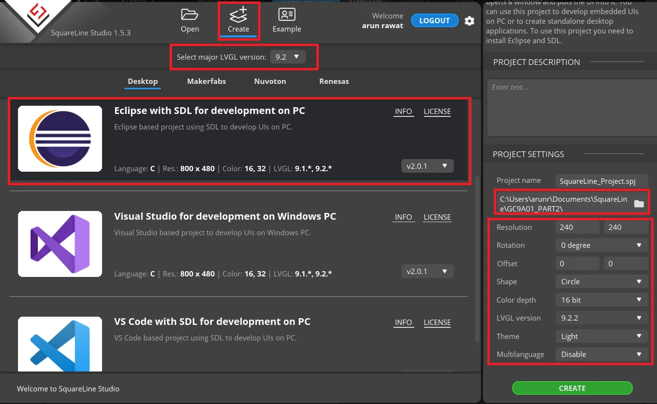
- In the Create tab, choose the latest LVGL version, i.e. 9.2 at this time.
- Select “Eclipse with SDL for development on PC”.
- On the right side, create a folder for the project.
- Now configure the display parameters:
- The GC9A01 is 240×240 Pixels with 16 bit color depth and circular display.
- Select the latest LVGL version, i.e. 9.2.2 at this time and click create to create the project.
Add clock Images
You need to download the PNG images for the clock face and its three hands, at a minimum. These images can be obtained from any reliable website that offers graphics in PNG format.
Now open the UI, Add the images to the Assets and then add them to the UI.
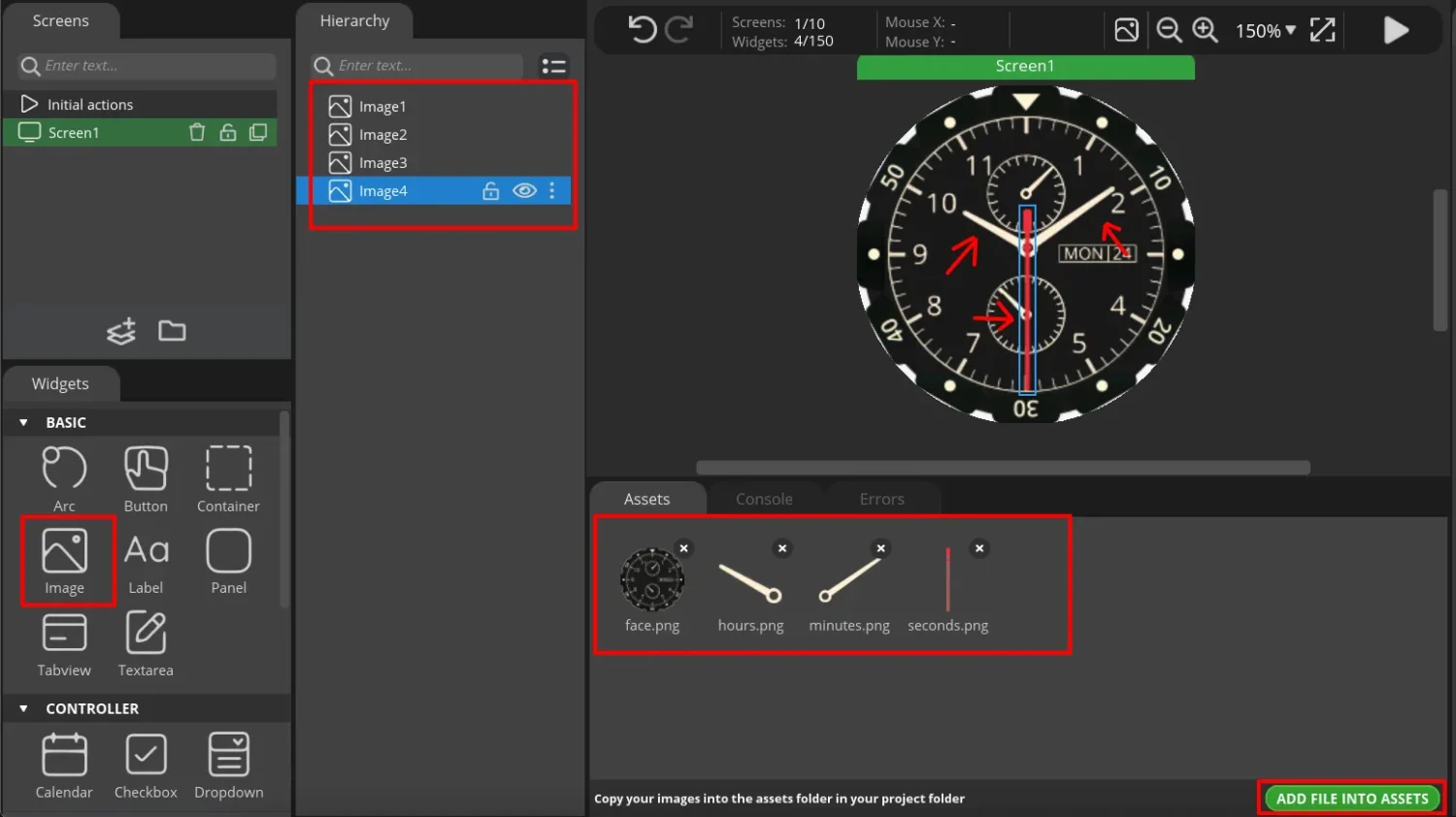
After adding the images to the UI, align them to the center of the clock face, just as how these hands are actually aligned on a real clock.
Rotating the Clock hands
To rotate a clock hand we need to rotate that specific image. The rotation should be about a fixed pivot point on the image. The coordinates of the pivot point can be identified by opening the image in an image editing software like GIMP. This is shown in the images below.
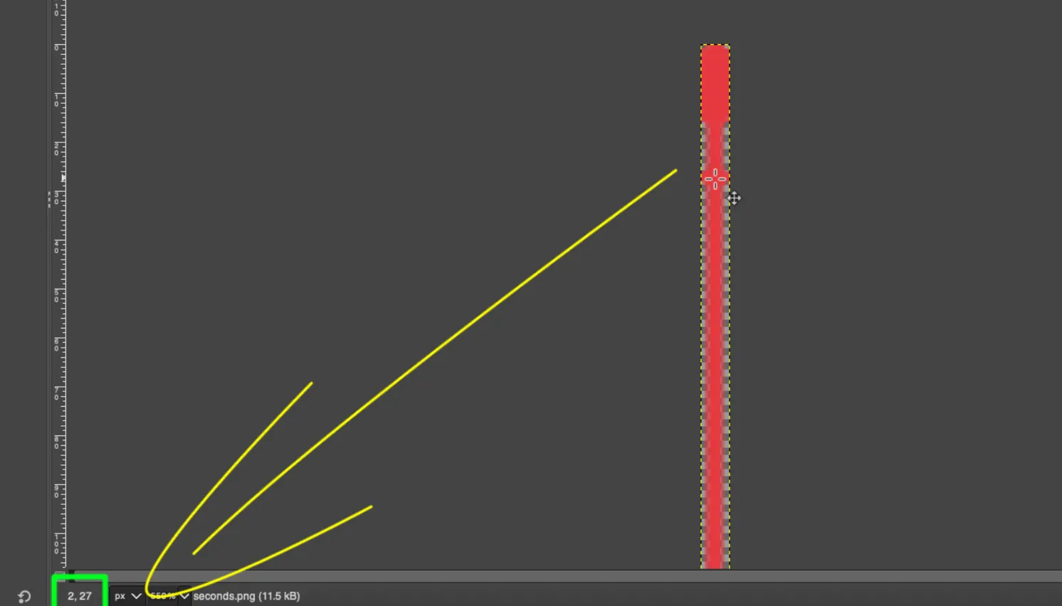
As shown above, when the mouse pointer hover over the point (where we want the pivot to be), the corresponding coordinates are displayed on the bottom left corner of the screen.
We will use these coordinates on the GUI design tool to rotate these clock hands about the pivot point. Let’s start with the Second’s Hand.
Second Hand
Below is the image showing the Second Hand configuration in the GUI.
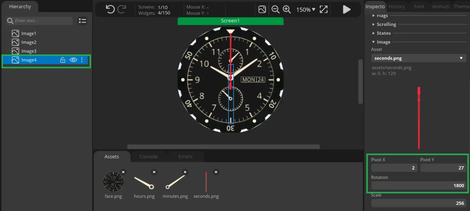
The pivot coordinates are set to match the exact values obtained from GIMP. After configuring the pivot you can test the movement by setting different rotation values. You will see that the hand’s movement is about the fixed point (pivot).
In terms of design, the second hand completes 60 rotation units every second. To align the hand at the 00:00 position, a rotation value of 1800 will be used as an offset for the second hand.
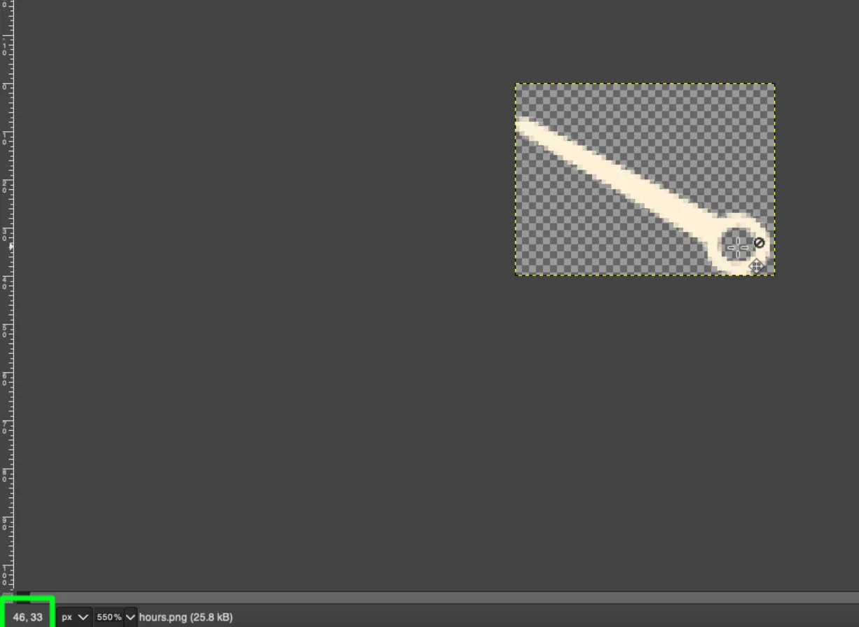
Hour Hand
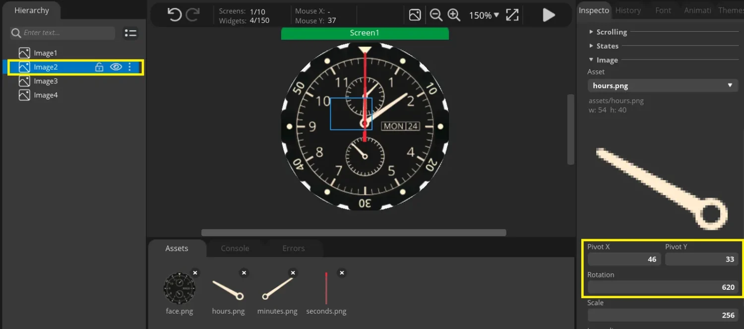
Similar to second hand, the pivot coordinates are set according to the value obtained from GIMP.
The Hour hand completes 300 rotation units every hour. This is because there are 5 divisions between two hours and each division is 60 rotation units apart. To align the hand at the 00:00 position, a rotation value of 620 will be used as an offset for the hour hand.
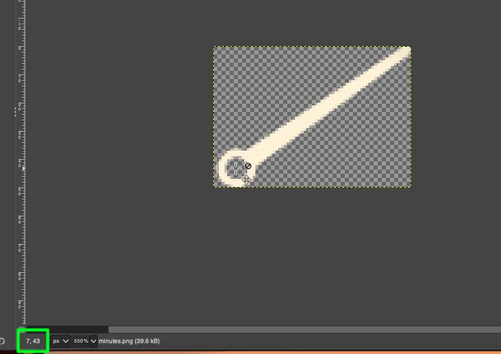
Minute Hand
Below is the image showing the Minute Hand configuration in the GUI.
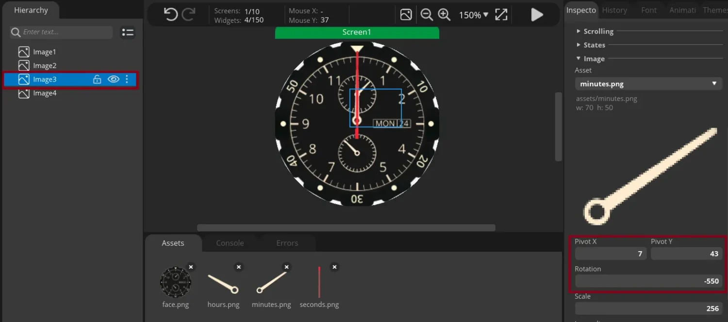
Similar to second hand, the pivot coordinates are set according to the value obtained from GIMP.
In terms of the clock design, the minute hand completes 60 rotation units every minute. To align the hand at the 00:00 position, a rotation value of -550 will be used as an offset for the minute hand. This value is negative because the minute hand is move in the CCK direction in order to align at 12’o clock.
Export the Design Files
With all three hands configured with their respective pivot points and aligned to the 00:00 position, we will proceed to export the UI files for integration into the STM32CubeIDE project.
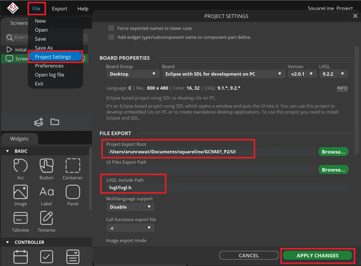
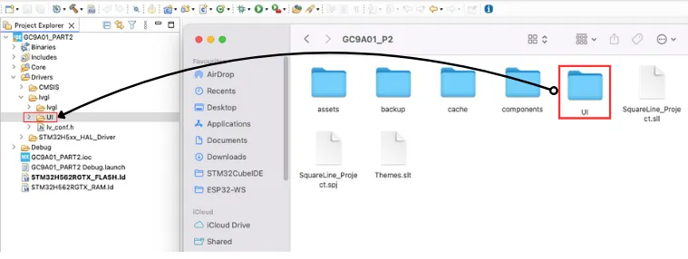
Open the Project Settings and set the path for the Project Export. The UI files will be exported to this path, so it is better to create a separate folder for this path. I am creating a new folder named “UI” inside the main project folder itself.
The LVGL include path must be set to lvgl/lvgl.h.
Now export the UI files into the folder we defined above.
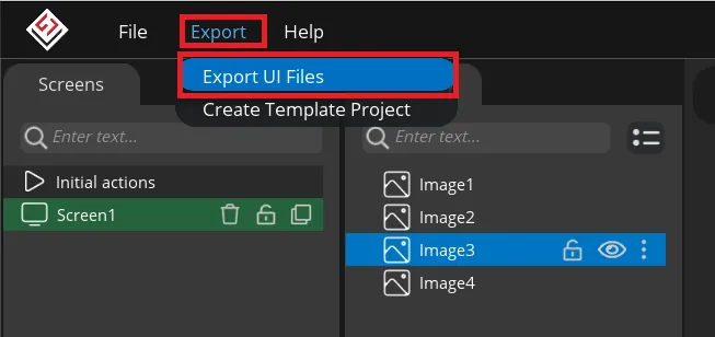
The GUI files will be exported to the defined folder, “UI” in my case. we can copy this entire folder inside our project folder where the LVGL is installed. This is shown in the image below.
STM32 RTC CONFIGURATION
The Connection between GC9A01 and STM32, SPI configuration for the display and LVGL implementation has already been covered in the previous tutorial, so we will not cover them here.
We will use the RTC to update the time on the analog clock. Below is the STM32 RTC configuration in the CubeMX.
RTC Source Clock configuration
I am utilizing the internal LSI oscillator to provide the clock source for the RTC. Alternatively, you can use an external LSE (32.768 kHz) crystal if it is available on your board.
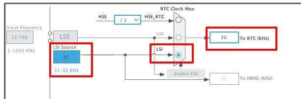
With the LSI being the clock source, the RTC source clock is configured to run at 32KHz.
RTC Parameter Configuration
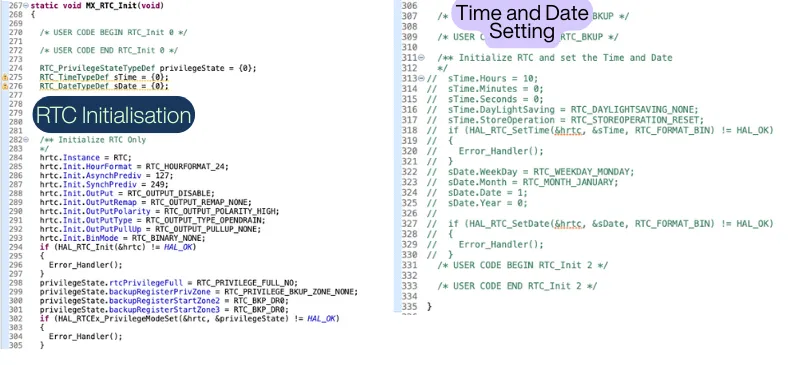
Below is the image showing the STM32 RTC configuration.
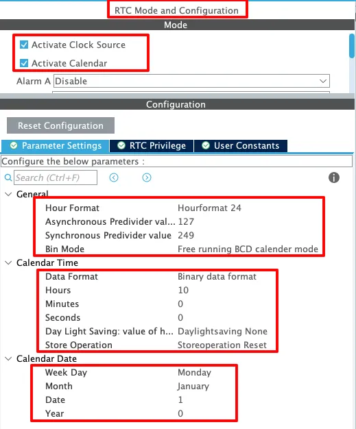
I configured the RTC to use the 24-hour time format with the data format set to binary. For now, you can assign placeholder values to the time and date; we’ll implement code-side functions to programmatically set these parameters.
The asynchronous and synchronous prescaler (predivider) values determine ck_spre. Choose them such that ck_spre = 1, as per the formula shown below.
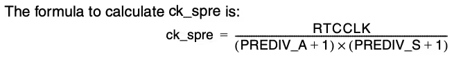
The RTCCLK is set to 32 KHz. By using a PREDIV_A value of 127 and a PREDIV_S value of 249 in the formula, the resulting ck_spre value equals 1Hz.
STM32 HAL CODE
The MX_RTC_Init() function is responsible for generating the initialization code for the RTC, including the configuration of time and date settings. However, if the time-setting section within this function is left active, the RTC will reset to the predefined values each time the microcontroller is reset and MX_RTC_Init() is executed again.
To prevent this behavior and ensure the RTC continues to keep accurate time across resets, we will comment out the time-setting portion of the code, allowing the RTC to retain its current time values.
Setting the time
Let’s define a separate function to configure the time.
void setTime (int hour, int min, int sec)
{
	if (HAL_RTCEx_BKUPRead(&hrtc, RTC_BKP_DR0) != 0x4321)
	{
		RTC_TimeTypeDef sTime = {0};
		sTime.Hours = hour;
		sTime.Minutes = min;
		sTime.Seconds = sec;
		sTime.DayLightSaving = RTC_DAYLIGHTSAVING_NONE;
		sTime.StoreOperation = RTC_STOREOPERATION_RESET;
		if (HAL_RTC_SetTime(&hrtc, &sTime, RTC_FORMAT_BIN) != HAL_OK)
		{
			Error_Handler();
		}

		HAL_RTCEx_BKUPWrite(&hrtc, RTC_BKP_DR0, 0x4321);
	}
}I have extracted this code from the pre-generated MX_RTC_Init() function and commented out the original time-setting section within it. This ensures that the RTC does not reinitialize to the same predefined time each time the MCU resets.
The parameters of the custom setTime function will be assigned to their respective fields, and the HAL_RTC_SetTime function will then update the RTC with the specified time values.
We will call the setTime function in the main function to configure the RTC with a predefined time. To prevent resetting the time on every restart, we use RTC backup register 0. The time-setting code is wrapped in an if condition that checks if backup register 0 holds 0x4321. If not, the time is set, and 0x4321 is written to the register. On subsequent resets, the presence of 0x4321 skips reconfiguration, preserving the current time.
0x4321 is a random value. The RTC_BKP_DR0 register does not contain this value when the function is called for the very first time. Therefore the respective time will be set and the value 0x43221 will be written to the RTC_BKP_DR0.
Update the Clock
Now we will read the time from the RTC and update the positions of the clock hands according to the time.
void updateClock (void)
{
	RTC_TimeTypeDef gTime;
	RTC_DateTypeDef gDate;

	HAL_RTC_GetTime(&hrtc, &gTime, RTC_FORMAT_BIN);
	HAL_RTC_GetDate(&hrtc, &gDate, RTC_FORMAT_BIN);

	int16_t rotn = (gTime.Seconds *60) + 1800;
	lv_img_set_angle(ui_Image2, rotn);

	rotn = (gTime.Minutes *60)-550 + gTime.Seconds;
	lv_img_set_angle(ui_Image5, rotn);

	rotn = (gTime.Hours *300)+620 + (gTime.Minutes*5);
	lv_img_set_angle(ui_Image4, rotn);

}- In this function, we first define the RTC time and date structures.
- Next, we call
HAL_RTC_GetTimeto read the current time, which will be stored in thegTimestructure using the binary data format for simplicity. - We also call
HAL_RTC_GetDate, even if the date is not needed, because reading the date is required to unlock the RTC shadow registers. - Finally, we update the clock hands using the current time data.
update Second hand
- The seconds hand advances 60 rotation units per second and has an initial offset of +1800.
- Declare a signed int
rotnto hold the rotation value. - Compute it as:
rotn = (gTime.Seconds * 60) + 1800; - This multiplies the elapsed seconds by 60 (units/second) and then adds the offset to align the hand.
- Apply the result with
lv_img_set_angle(ui_Image2, rotn);whereui_image2is the seconds-hand image.
update Minute hand
- The minute hand also advances 60 rotation units per minute and has an initial offset of -550.
- Compute the rotation as:
rotn = (gTime.Minutes * 60) - 550 + gTime.Seconds; - This multiplies the elapsed minutes by 60 (units/minute) and then adds the offset to align the hand. Finally add the seconds data to this result.
- The
gTime.Secondsis added to make the movement of the minute hand smoother. Without it, the minute hand will abruptly jump from 1 minute to 2 minutes in an instant. - Apply the result with
lv_img_set_angle(ui_Image5, rotn);whereui_image5is the Minutes-hand image.
Hour Minute hand
- The hour hand advances 300 rotation units per hour and has an initial offset of 620.
- Compute the rotation as:
rotn = (gTime.Hours * 300) + 620 + gTime.Minutes*5; - This multiplies the elapsed Hours by 60 (units/hour) and then adds the offset to align the hand. Finally add the minutes data to this result.
- The
gTime.Minutesis added to make the movement of the hour hand smoother. Without it, the hour hand will abruptly jump from 1 hour to 2 hours in an instant. The multiplication of 5 indicates that each minute sweeps 60 rotation units, therefore 50 minutes will sweep a total of 300 rotation units. - Apply the result with
lv_img_set_angle(ui_Image4, rotn);whereui_image4is the Minutes-hand image.
The main function
Below is the code for the main function.
int main()
{
  .....
  .....
  lv_init();
  lv_port_disp_init();

  ui_init();
  setTime(12, 12, 0);
  while (1)
  {
	  updateClock();

	  lv_timer_handler();
	  HAL_Delay(5);
  }
}Inside the main function, after initialising the LVGL and the display, we will initialise UI by calling the function ui_init();. The call the function setTime(12, 12, 0); to set the current time to the RTC.
Inside the while loop, along with the lv_timer_handler();, we will call the function updateClock(); to fetch the current time from the RTC and update the clock hands base on it.
RESULT
Below is the gif showing the Analog Clock GUI running on STM32.

You can now see that the clock is displaying the current time, which is 12 hours and 12 minutes. The seconds hand is ticking every second, and it is sweeping the correct angle for each tick.
VIDEO TUTORIAL
STM32 GC9A01 Video Tutorial
Prefer video? Watch the complete GC9A01 round display interfacing, SPI configuration, LVGL setup, and clock demo running in real time.
Watch the VideoConclusion
In this STM32 GC9A01 clock project, we demonstrated how to design an analog clock graphical user interface using SquareLine Studio and seamlessly integrate it with LVGL inside STM32CubeIDE. The tutorial also explained how to configure and use the STM32 Real-Time Clock (RTC) to retrieve the current time and continuously update the clock hands, ensuring smooth and accurate real-time operation on the round display.
This project builds directly on the concepts introduced in Part 1 of the series, where we covered the complete setup and interfacing of the GC9A01 round display with STM32 using SPI and LVGL. If you haven’t gone through that initial tutorial yet, it is recommended to read it first to understand the hardware connections, driver configuration, and basic LVGL integration before moving on to this clock application.
Check out more STM32 LVGL Tutorials
LVGL on STM32 || PART 2
LVGL on Riverdi STM32-H7 Display
LVGL on STM32 || PART 4
LVGL ON STM32 || PART5

LVGL on STM32 || PART 6
LVGL on STM32 || PART7 || Load LVGL from Ext Flash
How to Interface GC9A01 Round Display with STM32 Using SPI + LVGL Integration
STM32 GC9A01 Project Download
STM32 GC9A01 Display FAQs
Subscribe
Login
0 Comments
Newest
