Updated On: April 1, 2026
STM32 I2C Master Read Tutorial Using Low-Layer (LL) Drivers
In Part 1, we built an I2C scanner to detect devices. In Part 2, we learned to write data to I2C devices. Now we will complete the I2C cycle by reading data from sensors.
Reading from I2C devices is essential for retrieving sensor data. Whether it’s temperature, motion, or status information, the I2C read operation gets this data from the device’s registers. This tutorial shows how to perform I2C read operations using STM32 Low-Layer (LL) drivers.
We use the MPU6050 sensor for demonstration. We will read the WHO_AM_I register to verify device identity, then perform a burst read to get accelerometer data. This covers both single-byte and multi-byte read operations.
The read functions work with any register-based I2C device. You can adapt them for other sensors, RTCs, or peripherals. The core read sequence remains the same.
This works on any STM32 board. The examples use the STM32F446RE Nucleo, but the code stays identical across STM32 families.
Understanding I2C Read Operations
Reading data from I2C devices is more complex than writing. The master must first tell the device which register to read from, then switch to receive mode to get the data. Understanding this sequence helps us write correct read functions.
This section explains the I2C read protocol, the difference between single and multi-byte reads, and how register-based devices work.
How I2C Read Transaction Works
An I2C read operation actually involves both a write and a read. First, we write the register address we want to read from. Then we perform a read to get the data from that register.
Here is the complete sequence:
1. Generate START Condition
The master pulls SDA LOW while SCL is HIGH to begin the transaction.
LL_I2C_GenerateStartCondition(I2C1);
while(!LL_I2C_IsActiveFlag_SB(I2C1));2. Send Device Address with Write Bit
We send the device address with the write bit (0) because we need to write the register address first.
LL_I2C_TransmitData8(I2C1, (device_address << 1) | 0x00);
while(!LL_I2C_IsActiveFlag_ADDR(I2C1));
LL_I2C_ClearFlag_ADDR(I2C1);3. Send Register Address
We transmit the register address we want to read from.
LL_I2C_TransmitData8(I2C1, register_address);
while(!LL_I2C_IsActiveFlag_TXE(I2C1));4. Generate Repeated START Condition
Instead of sending STOP, we generate another START. This is called a Repeated START (Sr). It keeps the bus under our control.
LL_I2C_GenerateStartCondition(I2C1);
while(!LL_I2C_IsActiveFlag_SB(I2C1));5. Send Device Address with Read Bit
Now we send the device address again, but with the read bit set to 1.
LL_I2C_TransmitData8(I2C1, (device_address << 1) | 0x01);
while(!LL_I2C_IsActiveFlag_ADDR(I2C1));6. Read Data Bytes
The device sends data bytes and the master acknowledges each one. For the last byte, we send NACK instead of ACK to signal we’re done reading.
LL_I2C_AcknowledgeNextData(I2C1, LL_I2C_ACK);
LL_I2C_ClearFlag_ADDR(I2C1);
while(!LL_I2C_IsActiveFlag_RXNE(I2C1));
data = LL_I2C_ReceiveData8(I2C1);7. Generate STOP Condition
After receiving all data, we generate STOP to release the bus.
LL_I2C_AcknowledgeNextData(I2C1, LL_I2C_NACK);
LL_I2C_GenerateStopCondition(I2C1);The image below shows the I2C read transaction sequence with write phase and read phase.
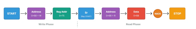
This two-phase approach is why reading takes longer than writing. We perform essentially two transactions back-to-back.
Single Register Read vs Multi-Byte Burst Read
I2C devices support two types of read operations: reading one register at a time, or reading multiple consecutive registers in one transaction.
Single Register Read
A single register read retrieves one byte of data from a specific register address. After reading that byte, we immediately send NACK and STOP.
Example: Reading the WHO_AM_I register from MPU6050.
// Read one byte from register 0x75
uint8_t data;
// Write phase: send register address
LL_I2C_GenerateStartCondition(I2C1);
while(!LL_I2C_IsActiveFlag_SB(I2C1));
LL_I2C_TransmitData8(I2C1, (0x68 << 1) | 0x00);
while(!LL_I2C_IsActiveFlag_ADDR(I2C1));
LL_I2C_ClearFlag_ADDR(I2C1);
LL_I2C_TransmitData8(I2C1, 0x75); // WHO_AM_I register
while(!LL_I2C_IsActiveFlag_TXE(I2C1));
// Read phase: get one byte
LL_I2C_GenerateStartCondition(I2C1);
while(!LL_I2C_IsActiveFlag_SB(I2C1));
LL_I2C_TransmitData8(I2C1, (0x68 << 1) | 0x01);
while(!LL_I2C_IsActiveFlag_ADDR(I2C1));
LL_I2C_AcknowledgeNextData(I2C1, LL_I2C_NACK); // Only one byte, send NACK
LL_I2C_ClearFlag_ADDR(I2C1);
while(!LL_I2C_IsActiveFlag_RXNE(I2C1));
data = LL_I2C_ReceiveData8(I2C1);
LL_I2C_GenerateStopCondition(I2C1);This reads exactly one byte and stops.
Multi-Byte Burst Read
A burst read retrieves multiple consecutive bytes in one transaction. The device automatically increments its internal register pointer after each byte. We send ACK for all bytes except the last one.
Example: Reading 6 bytes of accelerometer data (X, Y, Z axes, 2 bytes each).
// Read 6 bytes starting from register 0x3B
uint8_t data[6];

// Write phase: send starting register address
LL_I2C_GenerateStartCondition(I2C1);
while(!LL_I2C_IsActiveFlag_SB(I2C1));

LL_I2C_TransmitData8(I2C1, (0x68 << 1) | 0x00);
while(!LL_I2C_IsActiveFlag_ADDR(I2C1));
LL_I2C_ClearFlag_ADDR(I2C1);

LL_I2C_TransmitData8(I2C1, 0x3B);  // ACCEL_XOUT_H register
while(!LL_I2C_IsActiveFlag_TXE(I2C1));

// Read phase: get multiple bytes
LL_I2C_GenerateStartCondition(I2C1);
while(!LL_I2C_IsActiveFlag_SB(I2C1));

LL_I2C_TransmitData8(I2C1, (0x68 << 1) | 0x01);
while(!LL_I2C_IsActiveFlag_ADDR(I2C1));

LL_I2C_AcknowledgeNextData(I2C1, LL_I2C_ACK);  // Enable ACK for multiple bytes
LL_I2C_ClearFlag_ADDR(I2C1);

for(int i = 0; i < 6; i++)
{
    if(i == 5)  // Last byte
    {
        LL_I2C_AcknowledgeNextData(I2C1, LL_I2C_NACK);  // Send NACK
    }

    while(!LL_I2C_IsActiveFlag_RXNE(I2C1));
    data[i] = LL_I2C_ReceiveData8(I2C1);
}

LL_I2C_GenerateStopCondition(I2C1);This reads all 6 bytes in one transaction.
The image below shows the difference between single and burst read operations.
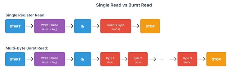
Key Difference:
- Single read: NACK immediately after the first byte
- Burst read: ACK for all bytes except the last one
Burst reads are much more efficient. Reading 6 registers individually would require 6 complete transactions. whereas, Reading them in one burst needs only one transaction.
Reading from Register-Based I2C Devices
Most I2C sensors and peripherals organize their data into registers. Each register has a unique address and contains specific information.
How Register-Based Devices Work:
The memory inside a device is arranged in Registers. Each register stores one byte of data. Some data spans multiple registers (like 16-bit temperature values).
Example: MPU6050 register map (partial):
| Register Address | Register Name | Purpose |
|---|---|---|
| 0x75 | WHO_AM_I | Device ID (always 0x68) |
| 0x3B | ACCEL_XOUT_H | Accelerometer X-axis high byte |
| 0x3C | ACCEL_XOUT_L | Accelerometer X-axis low byte |
| 0x3D | ACCEL_YOUT_H | Accelerometer Y-axis high byte |
| 0x3E | ACCEL_YOUT_L | Accelerometer Y-axis low byte |
| 0x3F | ACCEL_ZOUT_H | Accelerometer Z-axis high byte |
| 0x40 | ACCEL_ZOUT_L | Accelerometer Z-axis low byte |
| 0x41 | TEMP_OUT_H | Temperature high byte |
| 0x42 | TEMP_OUT_L | Temperature low byte |
Auto-Increment Feature:
Most I2C devices auto-increment their register pointer during burst reads. When you read from register 0x3B, the device sends that byte. Then it automatically moves to 0x3C for the next byte, then 0x3D, and so on.
This is why burst reads work. We only specify the starting register address once, and the device handles the rest.
Understanding this register-based structure makes working with any I2C sensor straightforward. Check the datasheet for the register map, then read the registers you need.
STM32CubeMX Configuration for I2C
We will use STM32CubeMX for the the initial setup. We only need to configure the I2C peripheral for scanning and USART for displaying the results. The clock setup and GPIO configuration are handled by CubeMX, so we can focus on writing the scanner logic instead of dealing with register-level details.
This section walks through creating a new project, enabling I2C1, setting up USART2 for output, and generating the final code.
STM32 Clock Configuration
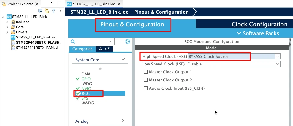
Before generating the project, we must configure the system clock. Open the Clock Configuration tab in CubeMX.
For the STM32F446RE, we will use the 8 MHz external crystal in bypass mode. This is the default clock source on the Nucleo board. The bypass mode uses the clock from the on-board ST-Link MCU.
We will feed this into the PLL and run the system at 180 MHz, which is the maximum frequency for this MCU.
The image below shows the complete PLL and clock configuration used to achieve 180 MHz.
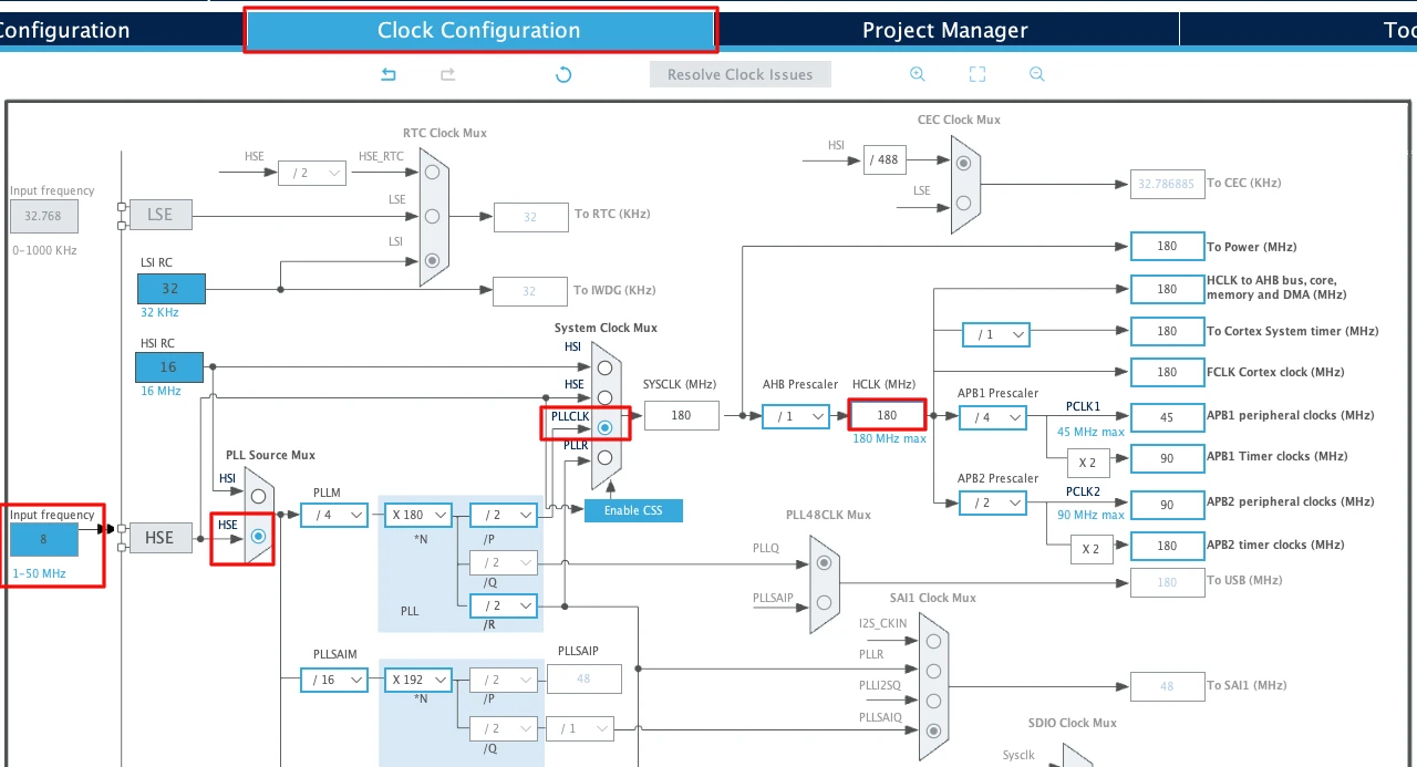
This fast system clock ensures accurate delays and smooth blinking using LL drivers. The SysTick timer will also run from this 180 MHz system clock, which becomes important in the delay functions we will use later.
Note for STM32F103C8
This MCU uses an 8 MHz external crystal as well, but its maximum frequency is 72 MHz. If you are using the Blue Pill, configure the PLL so that the final system clock is 72 MHz.
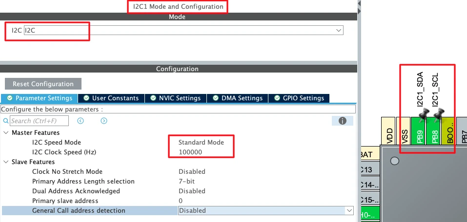
Configuring I2C1 Peripheral
I am going to use the I2C1 peripheral. Configure it in Standard Mode (100kHz), which is the most common I2C speed and works reliably with all devices.
The image below shows the I2C1 configuration in STM32CubeMX.
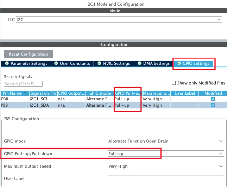
CubeMX automatically assigns the default I2C1 pins:
- PB6 → SCL (Clock Line)
- PB7 → SDA (Data Line)
These pins are standard for I2C1 on most STM32 boards. I have manually changes the pins to PB8 and PB9. These pins are easier to access on the nucleo boards.
Now configure the I2C parameters. Click on the Configuration tab under I2C1.
Set the following values:
- I2C Speed Mode: Standard Mode
- I2C Clock Speed: 100000 Hz (100 kHz)
Leave the rest of the settings at their default values.
STM32 microcontrollers support internal pull-up resistors on the I²C SCL and SDA lines. Enabling these pull-ups helps ensure proper bus idle levels when no external pull-up resistors or I²C devices are connected.
UART Configuration
I am going to use UART to print the ADC result on the serial console. I have already covered a tutorial explaining how to configure and use UART peripheral of the STM32 with LL drivers. The image below shows the UART configuration.
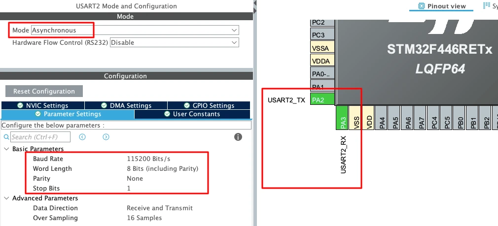
To enable USART2 in CubeMX:
- Set the Mode to Asynchronous.
- CubeMX automatically assigns the correct pins:
- PA2 -> TX
- PA3 -> RX
- Keep the Baud Rate to a common value like 115200.
Enabling the LL Drivers
Before generating the code, we need to enable LL drivers instead of HAL. This ensures CubeMX generates lightweight LL functions for I2C and USART.
Open Project Manager → Advanced Settings. Enable LL Drivers for all peripherals. This ensures CubeMX generates clean, lightweight LL code.
The image below shows the LL driver selection in CubeMX.
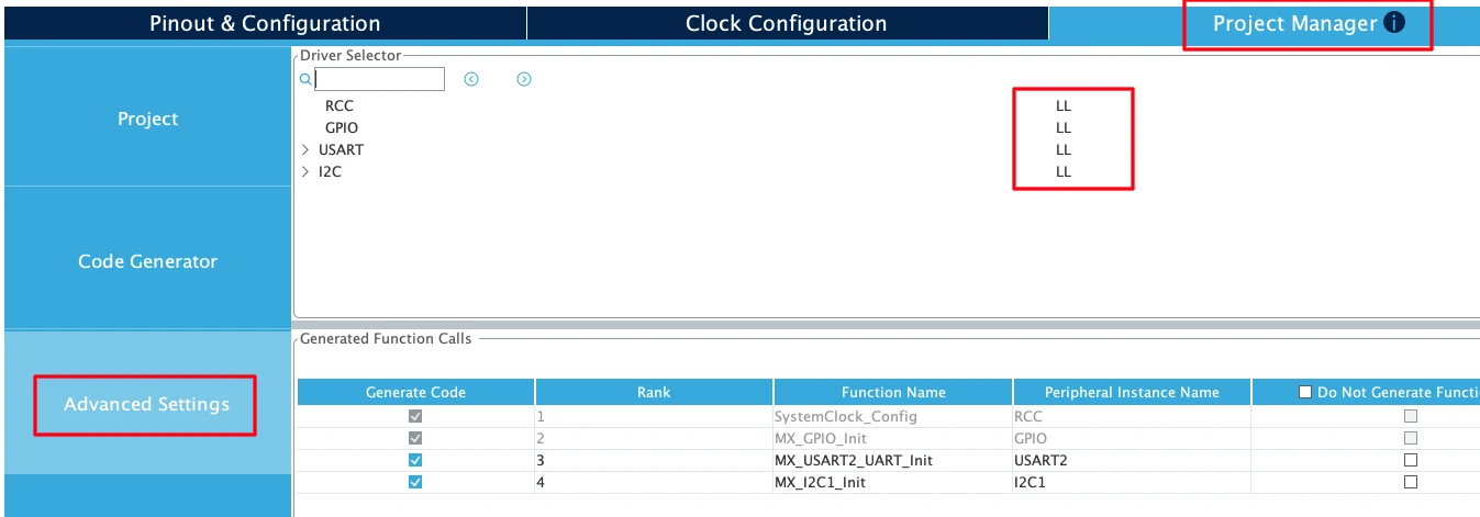
This step is critical. Without enabling LL drivers, CubeMX generates HAL code, which is heavier and not compatible with the LL functions.
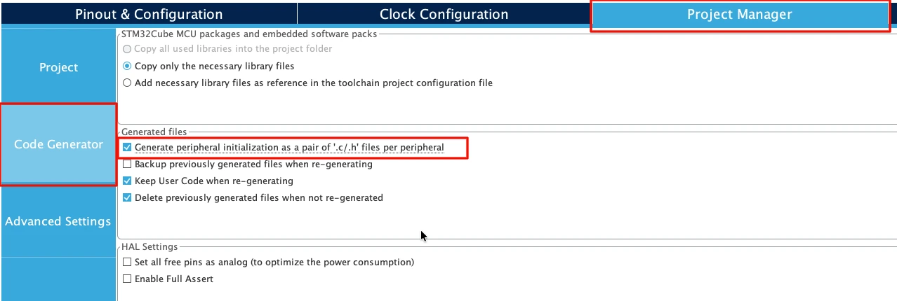
Next, go to Code Generator and select “Generate Peripheral Initialization as a pair of .c/.h files per peripheral”. This will generate a separate source files for all the peripherals we will use in a project.
Reading Data from MPU6050
Now we implement the I2C read operation to retrieve data from the MPU6050 sensor. We will create one universal function that handles both single-byte and multi-byte reads, then use it to read the device ID and accelerometer data.
Creating Universal I2C Read Function
We create one function that works for both single-byte and multi-byte reads.
void I2C_Mem_Read(uint8_t slaveAddress, uint16_t regAddress, uint8_t regLen, uint8_t *data, uint16_t length)
{
    // Write phase: Send register address
    LL_I2C_GenerateStartCondition(I2C1);
    while(!LL_I2C_IsActiveFlag_SB(I2C1));

    LL_I2C_TransmitData8(I2C1, (slaveAddress << 1) | 0x00);
    while(!LL_I2C_IsActiveFlag_ADDR(I2C1));
    LL_I2C_ClearFlag_ADDR(I2C1);

    if (regLen == 1)
    {
        LL_I2C_TransmitData8(I2C1, regAddress & 0xFF);
        while(!LL_I2C_IsActiveFlag_TXE(I2C1));
    }

    else if (regLen == 2)
    {
        // Send regAddress high byte
        LL_I2C_TransmitData8(I2C1, (uint8_t)(regAddress >> 8));
        while(!LL_I2C_IsActiveFlag_TXE(I2C1));

        // Send regAddress low byte
        LL_I2C_TransmitData8(I2C1, (uint8_t)(regAddress & 0xFF));
        while(!LL_I2C_IsActiveFlag_TXE(I2C1));
    }


    // Read phase: Get data bytes
    LL_I2C_GenerateStartCondition(I2C1);
    while(!LL_I2C_IsActiveFlag_SB(I2C1));

    LL_I2C_TransmitData8(I2C1, (slaveAddress << 1) | 0x01);
    while(!LL_I2C_IsActiveFlag_ADDR(I2C1));

    LL_I2C_AcknowledgeNextData(I2C1, LL_I2C_ACK);
    LL_I2C_ClearFlag_ADDR(I2C1);

    // Read all bytes
    for(uint16_t i = 0; i < length; i++)
    {
        if(i == length - 1)
        {
            LL_I2C_AcknowledgeNextData(I2C1, LL_I2C_NACK);  // If last byte, Send NACK
        }

        while(!LL_I2C_IsActiveFlag_RXNE(I2C1));
        data[i] = LL_I2C_ReceiveData8(I2C1);
    }

    LL_I2C_GenerateStopCondition(I2C1);
}This function takes five parameters:
slaveAddress: 7-bit I2C address of the EEPROM (typically 0x50)regAddress: 16-bit memory location where reading starts (8-bit address works too)regLen: Length of the register Address (1 or 2 bytes)data: Pointer to the data arraylength: Number of bytes to write
How It Works:
- Write phase sends the register address we want to read
- Repeated START switches to read mode
- Loop reads the specified number of bytes
- Send ACK for all bytes except the last one (NACK)
- STOP condition ends the transaction
This function works for any length: 1 byte, 6 bytes, or more.
Reading WHO_AM_I Register (Single Byte)
We test the function by reading the WHO_AM_I register. This register should return 0x68.
#define MPU6050_ADDRESS 0x68
#define WHO_AM_I_REG    0x75

uint8_t device_id;

int main(void)
{
    // ... CubeMX generated initialization code ...

    LL_mDelay(100);  // Sensor power-up delay

    // Read WHO_AM_I register
    I2C_Mem_Read(MPU6050_ADDRESS, WHO_AM_I_REG, 1, &device_id, 1);

    if(device_id == 0x68)
    {
        // MPU6050 detected successfully
    }

    while (1)
    {
    }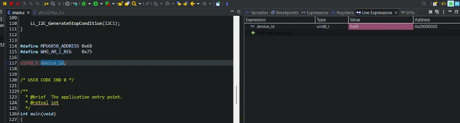
}This reads 1 byte from register 0x75. If we get 0x68, the sensor is connected and responding correctly.
Output:
The image below shows the debugger with device_id = 0x68.
Reading Accelerometer Data (Multiple Bytes)
Now we use the same function to read 6 bytes of accelerometer data in one transaction.
#define ACCEL_XOUT_H_REG  0x3B
#define PWR_MGMT_1_REG    0x6B

uint8_t accel_data[6];
int16_t accel_x, accel_y, accel_z;

int main(void)
{
    // ... initialization code ...
    // Wake up MPU6050 (disable sleep mode)
    uint8_t wake_command = 0x00;
    I2C_Mem_Write(MPU6050_ADDRESS, PWR_MGMT_1_REG, &wake_command, 1);
    while (1)
    {
        // Read 6 bytes starting from register 0x3B
        I2C_Mem_Read(MPU6050_ADDRESS, ACCEL_XOUT_H_REG, 1, accel_data, 6);

        // Combine bytes into 16-bit signed values
        accel_x = (int16_t)((accel_data[0] << 8) | accel_data[1]);
        accel_y = (int16_t)((accel_data[2] << 8) | accel_data[3]);
        accel_z = (int16_t)((accel_data[4] << 8) | accel_data[5]);

        LL_mDelay(100);
    }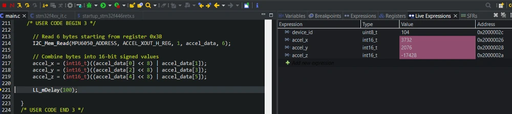
}Here we read 6 bytes starting from the address 0x3B. Then we combine the 6 bytes data into the three 16-bit acceleration data.
Output:
The image below shows live accelerometer data in the debugger.
Complete I2C Read Example
Now we combine everything into a complete example that reads multiple types of data from the MPU6050. This demonstrates how the same read function works for different register types and data sizes.
Combining Single and Multi-Byte Reads
We create a complete program that reads the device ID once at startup, then continuously reads accelerometer and temperature data.
#define MPU6050_ADDRESS   0x68
#define WHO_AM_I_REG      0x75
#define ACCEL_XOUT_H_REG  0x3B
#define TEMP_OUT_H_REG    0x41

uint8_t device_id;
uint8_t accel_data[6];
uint8_t temp_data[2];

int16_t accel_x, accel_y, accel_z;
int16_t temperature;

int main(void)
{
    // ... CubeMX generated initialization code ...

    /* USER CODE BEGIN 2 */

    LL_mDelay(100);

    // Read device ID once at startup
    I2C_Mem_Read(MPU6050_ADDRESS, WHO_AM_I_REG, &device_id, 1);

    if(device_id != 0x68)
    {
        // Device not found - handle error
        while(1);  // Stop here
    }

    /* USER CODE END 2 */

    while (1)
    {
      /* USER CODE END WHILE */

      /* USER CODE BEGIN 3 */

      // Read 6 bytes starting from register 0x3B
      I2C_Mem_Read(MPU6050_ADDRESS, ACCEL_XOUT_H_REG, 1, accel_data, 6);
      I2C_Mem_Read(MPU6050_ADDRESS, TEMP_OUT_H_REG, 1, temp_data, 2);

      // Combine bytes into 16-bit signed values
      accel_x = (int16_t)((accel_data[0] << 8) | accel_data[1]);
      accel_y = (int16_t)((accel_data[2] << 8) | accel_data[3]);
      accel_z = (int16_t)((accel_data[4] << 8) | accel_data[5]);

      temperature = (int16_t)((temp_data[0] << 8) | temp_data[1]);

      // Convert temperature
      float temp_c = (temperature / 340.0) + 36.53;

      // Send over UART
      char buffer[80];
      sprintf(buffer, "X:%d Y:%d Z:%d Temp:%.1fC\r\n", accel_x, accel_y, accel_z, temp_c);

      for(int i = 0; buffer[i] != '\0'; i++)
      {
          while(!LL_USART_IsActiveFlag_TXE(USART2));
          LL_USART_TransmitData8(USART2, buffer[i]);
      }

      LL_mDelay(100);
    }
}This program performs three different read operations:
- Single-byte read for device ID (once)
- Six-byte read for accelerometer (continuous)
- Two-byte read for temperature (continuous)
All three use the same I2C_Mem_Read() function with different parameters.
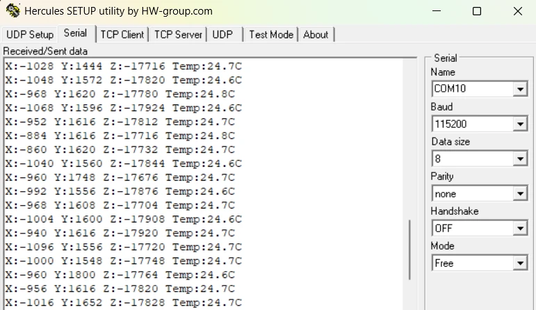
Output: Continuous Sensor Reading
The complete example continuously reads all sensor data. We can monitor the values using a debugger or UART.
UART Output:
The image below shows the serial terminal with continuous sensor readings.
This complete example demonstrates that one I2C read function handles all read scenarios efficiently.
Troubleshooting I2C Read Issues
I2C read operations can fail for several reasons. This section covers the most common problems and their solutions.
No Data Received from Sensor
If the read function completes but variables remain unchanged or show garbage values, the sensor is not responding.
Common Causes:
- Wrong I2C address: MPU6050 uses 0x68 by default, but becomes 0x69 if the AD0 pin connects to VCC. Run the I2C scanner from Part 1 to verify the address.
- Sensor in sleep mode: MPU6050 powers up in sleep mode by default. You must wake it by writing to the power management register:
// Wake up MPU6050 before reading
uint8_t wake_cmd = 0x00;
I2C_Mem_Write(0x68, 0x6B, 1, &wake_cmd, 1);
LL_mDelay(100);- Missing pull-up resistors: Check that SDA and SCL have 4.7kΩ resistors to VCC. Measure with a multimeter between SDA/VCC and SCL/VCC.
- Poor connections: Verify all wires are firmly connected. Try wiggling the wires while reading to check for intermittent connections.
Solution:
Always read WHO_AM_I first to confirm communication works before trying other registers.
Reading Only 0xFF or 0x00 Values
If every read returns 0xFF or 0x00 regardless of the register, the I2C bus has a problem.
0xFF Indicates:
- SDA line stuck HIGH (floating)
- No device pulling SDA LOW
- Sensor not powered
- Wrong device address
0x00 Indicates:
- SDA or SCL line stuck LOW
- Short circuit on the bus
- Device crashed mid-transaction
Solution:
- Power cycle everything (STM32 and sensor)
- Check SDA and SCL voltages with a multimeter:
- Both should read ~3.3V when idle
- If 0V, find the short circuit
- If >3.3V, check power supply
- Verify sensor VCC pin receives correct voltage (3.3V or 5V depending on module)
- Try a different sensor module if available
Conclusion
In this tutorial, we learned how to perform I2C read operations using STM32 Low-Layer (LL) drivers. We started by understanding the I2C read transaction, which involves both a write phase (sending the register address) and a read phase (receiving the data).
We created a universal I2C_Mem_Read() function that handles both single-byte and multi-byte reads. This same function works for reading one byte (WHO_AM_I register) or multiple bytes (accelerometer data). We tested it with the MPU6050 sensor by reading the device ID, accelerometer values, and temperature data.
The tutorial showed how to combine bytes into 16-bit values for sensors that store data across multiple registers. We also covered continuous reading for real-time sensor monitoring and troubleshooting common I2C read issues.
With Parts 1, 2, and 3 complete, you now have a full understanding of I2C communication using LL drivers: scanning for devices, writing data, and reading data. These skills work with any I2C peripheral, not just the examples shown.
Browse More STM32 LL Tutorials
STM32 UART using LL Drivers (Part 4): Receive Data in Interrupt Mode
STM32 UART using LL Drivers (Part 5): Receive Using DMA (Normal and Circular Mode)
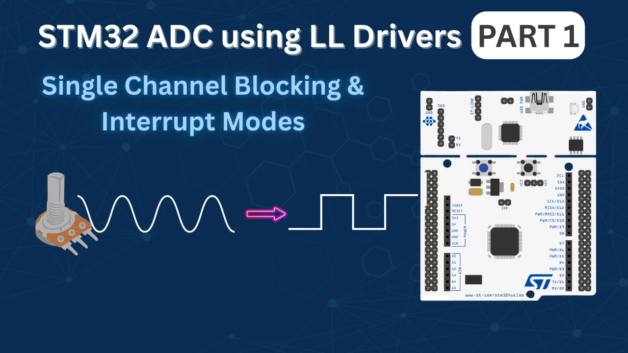
STM32 ADC Using LL Drivers (Part 1): Single Channel Blocking and Interrupt Mode
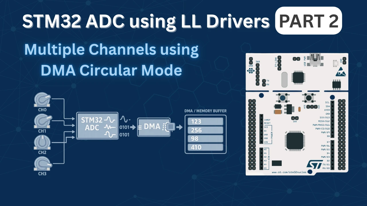
STM32 ADC Using LL Drivers (Part 2): Multiple Channels using DMA Mode
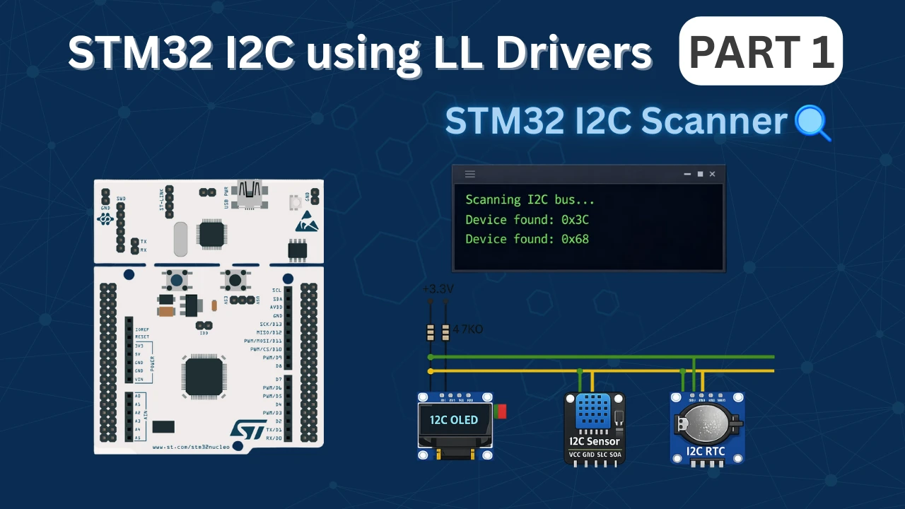
STM32 I2C using LL Drivers (Part 1): I2C Scanner to Detect I2C Devices with STM32CubeMX
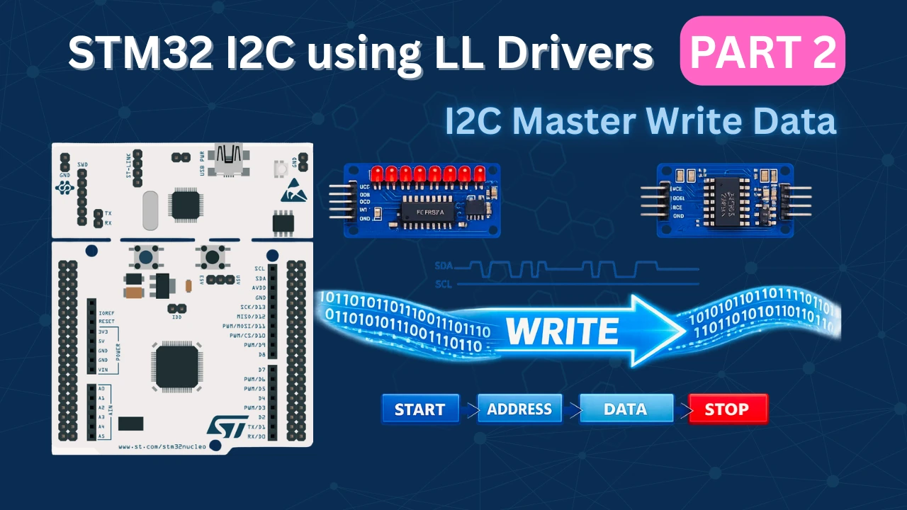
STM32 I2C Using LL Drivers (Part 2): Write Data to EEPROM and I/O Expander
STM32 LL I2C Project Download
STM32 LL I2C FAQs

Subscribe
Login
0 Comments
Newest
