Updated On: April 1, 2026
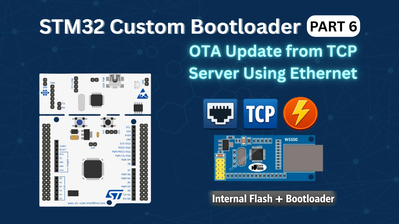
STM32 OTA Bootloader PART 6: Flashing OTA Update from TCP Server Using Ethernet
In this STM32 Custom bootloader series, we have been building everything step by step. In the previous parts, we created a custom bootloader, defined an application header, added firmware validation, and tested basic OTA flows.
In Part 6, we finally implement a real OTA update from a TCP server.
Here, the firmware is sent from a TCP server over Ethernet and received by the STM32 using the W5500 Ethernet module. The application works as a TCP client. It connects to the server, downloads the OTA file, and stores it inside the flash memory.
Once the download is complete, the application sets the OTA flag and resets the MCU. After reset, the bootloader takes control, validates the firmware, flashes the update, and jumps to the new application.
To store the OTA file, we split the internal flash memory into two parts. One part is used to store the OTA image, and the other part is used for the actual application.
This setup makes the internal flash behave like a dual-flash system, which is useful for devices with larger flash memory such as the STM32F446.
In this tutorial, we will configure the application for Ethernet-based OTA, implement a TCP client, write the OTA safely into flash memory, and test the complete update flow.
The entire process is automated. There is no need to manually calculate CRC, update sizes, or copy files between projects.
OTA Flash Memory Layout for STM32F446
Before we start implementing the OTA logic, we need to decide where the OTA image will be stored. Since we are not using any external flash in this part, the OTA file must be stored inside the internal flash memory itself.
To achieve this, we split the internal flash into multiple regions. One region is used to store the OTA image, and another region is used to store the main application.
This approach works well on MCUs with large flash memory, such as the STM32F446, and it allows us to simulate a dual-flash setup using a single internal flash.
Why Flash Splitting Is Required for OTA
During an OTA update, the new firmware cannot overwrite the currently running application. If we try to do that, the MCU will crash because the code being executed is getting erased. To avoid this problem, we need a separate flash region where the new firmware can be stored safely.
So the idea is simple.
- The application downloads the OTA file and stores it in a dedicated flash area
- The bootloader reads the OTA image from this area
- The bootloader then flashes the new firmware into the application area
This is why flash splitting is required for any reliable OTA implementation.
Flash Layout Used in STM32F446
The STM32F446 comes with 512KB of internal flash memory, which makes it suitable for this approach. The flash memory in this MCU is divided into sectors, and each sector must be used completely. We cannot use partial sectors.
In our case, we divide the flash memory into the following parts:
- Bootloader
- Application header
- OTA storage area
- Application area
Each of these parts occupies one or more complete flash sectors.
OTA and Application Memory Regions
The image below shows the flash layout used in this project.
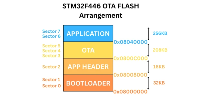
Below is the description for each section shown in the image.
- Bootloader
- Size: 32KB
- Flash sectors: Sector 0 and Sector 1
- Start address: 0x08000000
- Application Header
- Size: 16KB
- Flash sector: Sector 2
- Start address: 0x08008000
- OTA Storage Area
- Size: 208KB
- Flash sectors: Sector 3, 4, and 5
- Start address: 0x0800C000
- Application Area
- Size: 256KB
- Flash sectors: Sector 6 and Sector 7
- Start address: 0x08040000
Because the flash is arranged in sectors, we must use full sectors for each region. This is the reason the OTA and application areas are not split equally.
This flash layout is defined inside the flash_layout.h file, which is shared between the application and the bootloader.
Configuring Application Project for TCP OTA Update
Now that the flash layout is defined, we can start modifying the application project. In this section, we will configure the STM32CubeMX to connect the STM32 to a TCP server using Ethernet.
I am going to use the W5500 SPI Ethernet module to connect the STM32F446 to the ethernet. I have already covered an entire series on STM32 Ethernet using W5500, so do check it out if you face any difficulty configuring it.
Enabling SPI for W5500 Ethernet Module
The W5500 communicates using SPI, so we need to enable one SPI peripheral. The image below shows the SPI1 configuration for W5500 Ethernet Module.
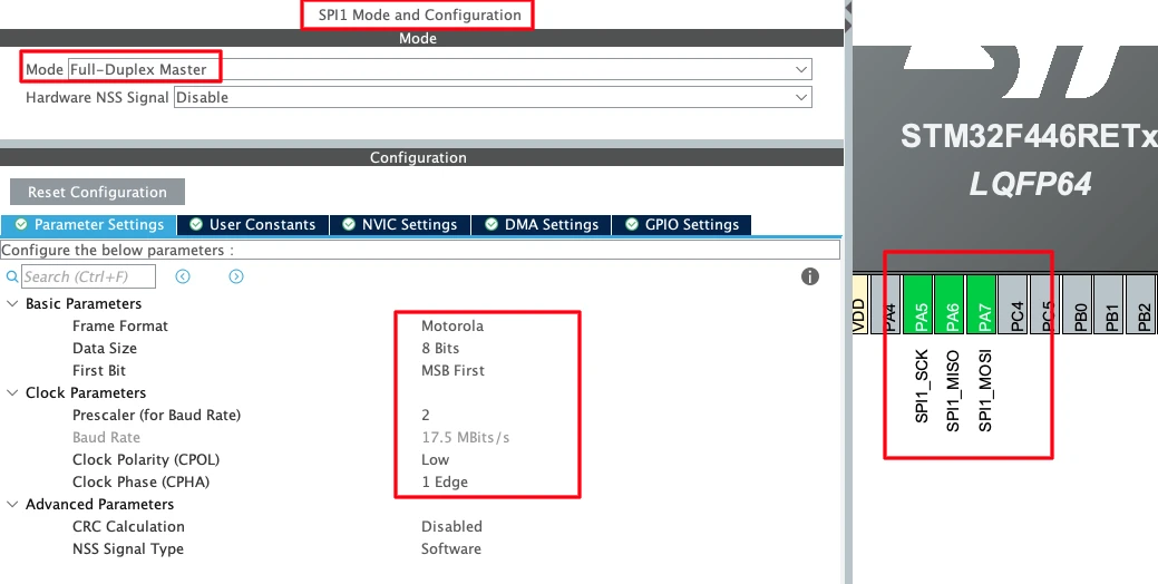
Configure SPI1 with the following settings:
- Mode: Full-Duplex Master
- Data Size: 8-bit
- First Bit: MSB First
Set the prescaler such that the SPI clock stays close to 20 Mbps. This speed works reliably with the W5500 module.
Once enabled, CubeMX will automatically assign the SPI pins:
- PA5 → SPI Clock
- PA6 → MISO
- PA7 → MOSI
These pins are enough for SPI communication with the Ethernet module.
Configuring GPIO, CS, RESET, and LED Pins
Apart from the SPI pins, the W5500 module also needs Chip Select and Reset pins. Select two free GPIO pins and configure them as Output mode.
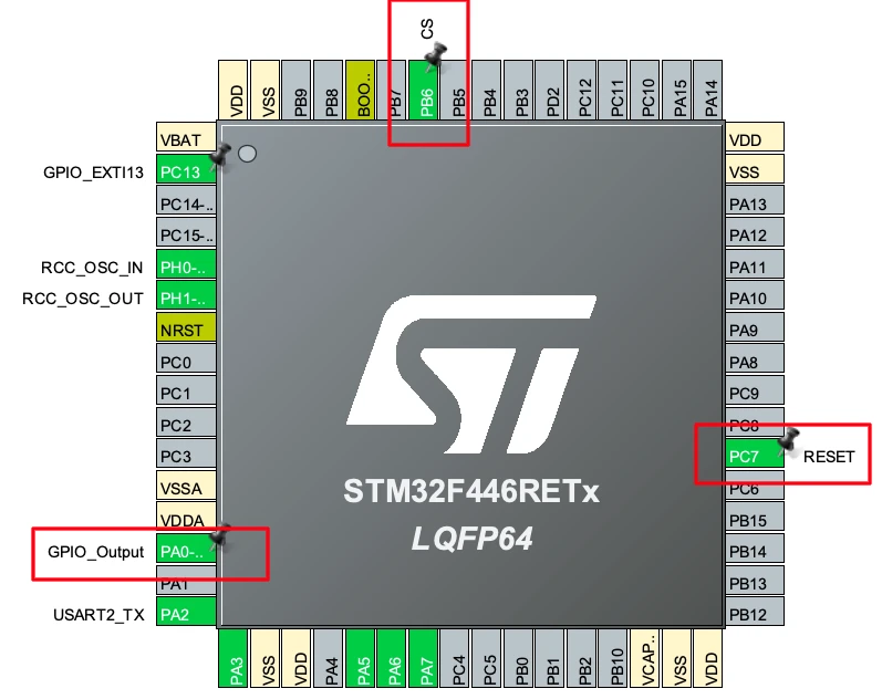
- PB6 is used as W5500 CS
- PC7 is used as W5500 RESET
Make sure to name these pins clearly in CubeMX. This makes the code easier to read and maintain.
I am also configuring one extra GPIO pin (PA0) as an output for an LED. This LED will be used to show that the application is running normally.
Adding W5500 and Ethernet Libraries
After generating the project, we need to add the Ethernet-related libraries.
First, copy the W5500 library folder and paste it inside the Drivers directory of the application project. This is shown in the image below.
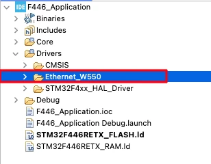
This folder contains the basic driver files required for:
- SPI communication with W5500
- Socket handling
- Network configuration
I have already explained these files in detail in the earlier W5500 series, so we will not go deep into them again here. You can get this folder after downloading the project from the end of this post.
Updating Include Paths in STM32CubeIDE
After adding new folders, we must update the include paths. If we skip this step, the compiler will not be able to find the header files.
Go to Project Properties → C/C++ Build → Settings → MCU/MPU GCC Compiler → Include Paths, and add the path to the folder we just copied (Ethernet W5500).
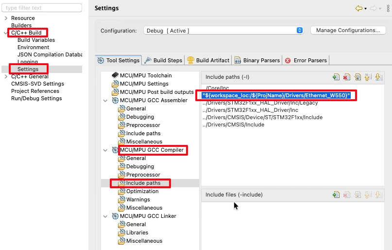
Once added, apply the changes and close the settings. Now the compiler can correctly recognize all Ethernet and W5500-related files.
Connecting W5500 to STM32
Once the STM32 project is configured, the next step is to connect the W5500 Ethernet module to the STM32 board. Proper wiring is essential for reliable SPI communication and stable Ethernet operation. In this section, we’ll look at the pinout and power requirements.
W5500 Pinout and Wiring Diagram
The W5500 module from Wiznet has a standard pinout for SPI communication and control. The image below shows how the STM32F446RE Dev board is connected to W5500 Ethernet Module.
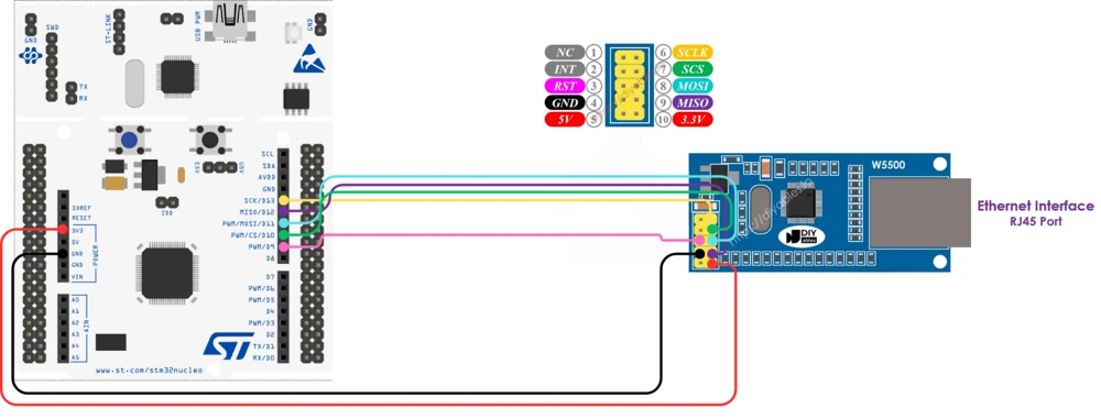
Here’s a quick overview of the important pins you’ll need to connect to the STM32:
| W5500 Pin | Function | STM32 Pin (Example – Bluepill) |
|---|---|---|
| SCS (CS) | Chip Select | PB6 |
| SCLK (SCK) | SPI Clock | PA5 |
| MISO | Master In Slave Out | PA6 |
| MOSI | Master Out Slave In | PA7 |
| RST | Reset Pin | PC7 |
| 3V3 | Power Supply | 3.3V Output |
| GND | Ground | GND |
You can follow this wiring whether you’re using the STM32F103, STM32F4, or similar boards. Make sure all grounds are connected together, this is very important for stable SPI communication.
Power Supply and Communication Pins
The W5500 module operates at 3.3V, so it can be powered directly from the STM32 board’s 3.3V pin. Do not power it from 5V, as that can permanently damage the IC.
For communication:
- The SPI pins (SCK, MISO, MOSI) handle data exchange between the STM32 and W5500.
- The CS (Chip Select) pin allows the MCU to enable or disable communication with the module.
- The RESET pin ensures proper startup of the W5500 and can be toggled by the STM32 if required.
The RJ45 port on the W5500 can be connected directly to your router or network switch using a standard Ethernet cable. This connection allows the W5500 to obtain an IP address through DHCP.
Otherwise if you would like to use the Static IP, connect the cable directly to your computer.
TCP OTA Client Implementation in STM32
In this section, we will implement the TCP client using W5500, handle OTA flash writing, and finally add a trigger mechanism so OTA does not run all the time.
Implementing TCP Client Logic Using W5500
We start by creating a raw TCP client using the W5500 Ethernet chip. The client connects to a TCP server and requests the firmware file. The code is placed in a separate file called OTA_TCP_Client.c.
First, we define the server IP, port, and socket configuration.
#define SERVER_IP   {192, 168, 1, 2}
#define SERVER_PORT 5678

#define CLIENT_SOCKET 0
#define CLIENT_PORT 1234If DNS is enabled, the hostname is resolved first. Otherwise, a static IP is used.
The client socket is opened in TCP mode and then connected to the server.
ret = socket(CLIENT_SOCKET, Sn_MR_TCP, CLIENT_PORT, 0);
ret = connect(CLIENT_SOCKET, server_ip, SERVER_PORT);Once the connection is established, the client sends a simple request.
const char req[] = "GET firmware\r\n";
send(CLIENT_SOCKET, (uint8_t*)req, strlen(req));This tells the server to start sending the firmware binary.
Receiving OTA Firmware Data from TCP Server
After sending the request, the client waits for incoming data. The received data is stored in a buffer.
len = recv(CLIENT_SOCKET, rx_buf, rx_size);Each received chunk is passed to a processing function.
ota_process_rx(rx_buf, len);To maintain reliability, the client sends an ACK after every chunk.
send(CLIENT_SOCKET, (uint8_t*)"A", 1);This simple flow control avoids buffer overflow and packet loss.
Writing OTA Data to Internal Flash Memory
Now we handle the most critical part: writing firmware to flash.
Flash memory on STM32 cannot be written byte by byte. It must be written in word-aligned blocks. That is why we process the data carefully before writing.
The flash is erased only once, before the first write.
if (!flash_erased)
{
    ota_erase_flash();
    flash_erased = 1;
}The firmware image starts with an OTA header. This header contains metadata like image size and version.
The header is received first and written to flash.
ota_write(flash_offset, data, hdr_bytes_needed);
flash_offset += hdr_bytes_needed;After the header, the actual firmware body is written sequentially.
ota_write(flash_offset, &data[offset], fw_bytes_to_write);
flash_offset += fw_bytes_to_write;This continues until the full image is received.
OTA Completion and Flash Write Finalization
Once all bytes are received, we finalize the OTA process.
if (bytes_received >= ota_hdr.image_size + OTA_HEADER_SIZE)
{
    ota_finalize();
}At this point:
- The socket is closed
- A bootloader flag is set
- The system is reset
enable_ota_request();
NVIC_SystemReset();After reset, the bootloader detects the flag and boots into the new firmware.
Adding an OTA Trigger Mechanism
We do not want OTA to run every time the device boots. So we add a manual trigger using a button.
A GPIO interrupt is used to set a flag.
uint8_t ota_begin = 0;

void HAL_GPIO_EXTI_Callback(uint16_t GPIO_Pin)
{
    ota_begin = 1;
}Inside the main loop, we check this flag.
if (ota_begin == 1)
{
    ota_begin = 0;
    ota_start();
}Once OTA starts, the application stays inside the OTA task loop.
while (ota_active == 1)
{
    OTA_Client_Task();
    HAL_Delay(5);
}During normal operation, the application continues running.
HAL_GPIO_TogglePin(GPIOA, GPIO_PIN_0);
HAL_Delay(200);This ensures OTA only runs when explicitly triggered.
The main functions to look for
The TCP client is a very lengthy file and it can get confusing. There are few implementations you need to look for and they are as follows.
- The server IP and Port should be set correctly. Here I am running a local python based TCP server on my computer, hence I have used a local IP address. You can get the
server.pyfile inside the project you will download at the end of the post.
#define SERVER_IP  			{192, 168, 1, 2}
#define SERVER_PORT 5678- The variable
flash_offset = OTA_START_ADDR; defines the flash memory address, where the OTA will be stored to. Although this address is defined in flash_layout.h file, but double check it to make sure the address is correct.
If you want to store the OTA on some external storage, set thisflash_offsetvariable to 0. - The function
void ota_write (uint32_t addr, uint8_t *buf, size_t len)is responsible for writing the OTA to the provided memory location. Since here I am using an internal flash memory to store the OTA update, the function is implemented as shown below.
static void ota_write (uint32_t addr, uint8_t *buf, size_t len)
{
	HAL_FLASH_Unlock();
	flash_write_bytes(addr, buf, len);
	HAL_FLASH_Lock();
}If you want to use an external storage, change this function according to your requirement.
Updating Bootloader to Read OTA from Flash
Now we move to the bootloader side. At this point, the application has already downloaded the firmware and stored it in internal flash. Our job here is to teach the bootloader how to read that stored OTA image correctly and copy it to the application area.
The OTA stream format and header layout are already explained in the previous tutorial, so we will not repeat that part here. Instead, we will focus only on how the bootloader reads OTA data from internal flash as a stream, just like it would from external memory.
Updating Flash Layout in Bootloader
The first thing we do is make sure the bootloader knows where the OTA image starts. In our case, the OTA image is stored in internal flash, starting at OTA_START_ADDR. We use a base address and a cursor. This makes the design flexible. The same logic can work with internal flash, external flash, or even dual-flash setups.
Here is the updated bootloader memory setup:
static uint32_t mem_base = OTA_START_ADDR;  // used with external or dual flash
static uint32_t mem_cursor = 0;
static uint32_t ota_image_total_size = 16; // expected OTA Header sizemem_basepoints to the start of the OTA imagemem_cursortracks how much data we have already readota_image_total_sizelimits how much data the bootloader is allowed to read
Reading OTA Image from Flash Memory
Instead of reading the full OTA image at once, the bootloader reads it step by step, just like a data stream. This is important because the same bootloader logic can later support different memory sources without changes.
The function below is used to tell the bootloader how large the OTA image is:
void ota_mem_set_total_size(uint32_t size)
{
    ota_image_total_size = size;
}Once the size is set, the bootloader starts reading chunks from flash using a common read function.
Copying OTA Data Using memcpy
The actual flash read is very simple. STM32 internal flash is memory-mapped, so we can directly use memcpy(). Here is the core read function used by the bootloader:
int ota_read_mem(uint8_t *buf, uint32_t len)
{
    if (mem_cursor + len > ota_image_total_size)
        return -1;

    uint8_t *flash_ptr = (uint8_t *)(mem_base + mem_cursor);

    memcpy(buf, flash_ptr, len);

    mem_cursor += len;
    return 0;
}What happens here is very straightforward:
- The function checks if the requested read exceeds the OTA image size
- It calculates the flash address using base + cursor
- Data is copied into a buffer using
memcpy() - The cursor is advanced for the next read
This makes the OTA image behave like a continuous data stream, even though it is stored in flash.
Bootloader OTA Flash and Validation Flow
With this setup, the bootloader OTA flow becomes very clean and structured:
- Bootloader sets OTA image size after reading the header
- OTA data is read in chunks using
ota_read_mem() - Validation logic works exactly like before
- Application flash is erased and written
- Bootloader updates the Application header and jumps to the updated application
Because the stream layout is already defined in the earlier tutorial, the same OTA parsing and validation logic works without any change.
Flashing Bootloader and Application Correctly
Now that both the bootloader and application are ready, we must flash them in the correct order. This step is very important. If the flashing sequence or address is wrong, the system will not boot correctly.
Flashing Bootloader Using STM32CubeProgrammer
We always flash the bootloader first. The bootloader lives at the start of flash and controls everything that happens during reset.
Open STM32CubeProgrammer and connect the board using ST-Link. You can directly flash the ELF file generated by the bootloader project. This is useful because you do not need to manually enter the flash address.
Once flashing is complete, disconnect the ST-Link and reset the board.
Flashing Application Using STM32CubeIDE
Next, we flash the application project. Unlike the bootloader, the application must be flashed once from CubeIDE so it can run and download the OTA update.
- Open the application project in STM32CubeIDE.
- Click on Debug instead of Run. This allows us to control the start address properly.
- Create a new debug configuration if prompted.
- Go to the Startup tab in the debug configuration.
- Enable Specify Vector Table and enter the start address of the application flash region. This must match the application start address defined in the flash layout.
- Once this is done, click Debug.
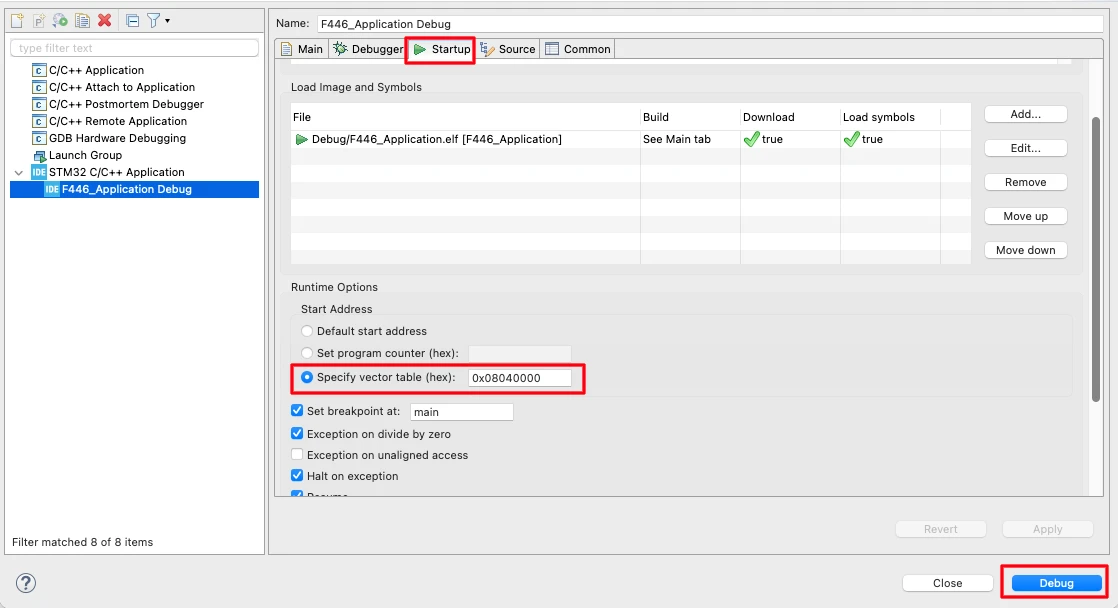
After the application loads, click the Run button to start execution.
Creating and Running TCP OTA Server
In this section, we will look at the Python-based TCP OTA server used to send the firmware to the STM32 device. This server is simple, reliable, and easy to modify. You can find this server file directly inside the project folder, so there is no need to create it from scratch.
We will not explain the full script here. Instead, I will focus only on the configuration part, which is what you usually need to change.
OTA Server Python Script Overview
The OTA server is a basic TCP socket server written in Python.
Its job is simple:
- Wait for a TCP client connection
- Receive a small request from the STM32
- Send the OTA binary file in fixed-size chunks
Once the transfer is complete, the server closes the connection.
Server IP, Port, and OTA Binary File
At the top of the script, you will find all the important configuration values.
SERVER_IP = "0.0.0.0"
SERVER_PORT = 5678
IMAGE_FILE = "ota_image.bin"Here is what each one means:
SERVER_IP = "0.0.0.0"
This allows the server to listen on all network interfaces.SERVER_PORT = 5678
This port must match the port configured in the STM32 TCP client.IMAGE_FILE = "ota_image.bin"
This is the OTA binary file generated from the application project.
Make sure this file is present in the same directory where you run the script.
OTA Data Transmission Flow
The chunk-based transfer behavior is also configurable.
CHUNK_SIZE = 512
CHUNK_DELAY = 0.25 # 250 msCHUNK_SIZEdefines how many bytes are sent in one TCP packet.
This value matches the receive buffer size used on the STM32 side.CHUNK_DELAYadds a small delay between chunks.
This prevents buffer overflow and keeps the transfer stable.
The server waits for a request from the client and then starts sending the firmware.
print("Waiting for START command from client...")
cmd = conn.recv(64)
print("START received. Sending firmware...")Once the request is received, the OTA file is transmitted chunk by chunk until the full image is sent.
Testing OTA Update Over Ethernet
In this section, we will verify the complete OTA update flow over Ethernet. At this stage, both the application and the bootloader are ready, and the TCP OTA server is running. Now we will observe how the system behaves before the update, during the OTA process, and after the new firmware is flashed.
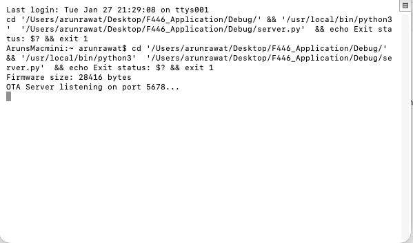
Observing Server Logs
First, start the Python OTA server on your PC. Once the server starts, it begins listening for incoming TCP connections.
You should see logs indicating that the server is waiting for a client and is ready to send the OTA file. The image below shows the server logs displaying that the TCP server is listening and ready to accept a client connection.
OTA Download and Flash Process
We used the debugger to tun the application , so the application is already running on the STM32 board. Next, press the OTA trigger button on the STM32 board.
Once the button is pressed:
- The W5500 module is initialized
- An IP address is assigned
- The TCP client connects to the OTA server
- The OTA request is sent to the server
The server then starts transmitting the OTA binary file. The image below shows the logs generated by the server.
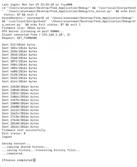
On the client side, the firmware is received in chunks and written directly to the internal flash memory. The image below shows the logs generated by the application running on STM32.
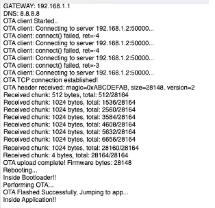
It start by initializing W5500 module. Then it connects to the server and sent OTA request. The client then receives all the data sent by the server. After the complete OTA image is received, the application resets the MCU.
After the reset, the bootloader runs automatically.
The bootloader:
- Reads the OTA image from flash
- Verifies the firmware
- Flashes it into the application region
- Jumps to the new application
Now the updated application starts running.
Note:
You can check the video at the end of this post to see the complete working.
Verifying Application Version After OTA
After the OTA update is complete and the system boots into the new firmware, we should always verify that the correct application has been flashed. The easiest and safest way to do this is by using STM32CubeProgrammer.
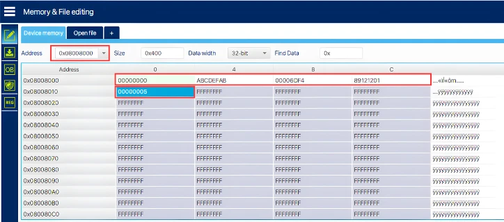
Reading Application Header from Flash
Open STM32CubeProgrammer and connect the STM32 using ST-Link. Once connected, go to the Memory & File Editing section. Here, read the flash memory region where the application header is stored.
The application header contains important metadata such as:
- Magic number
- Firmware size
- CRC
- Application version
This header is written by the bootloader after a successful OTA flash. The image below shows the application version field in STM32CubeProgrammer, confirming that the OTA update was applied successfully.
Video Tutorial
STM32 Ethernet OTA Update – TCP Server Demo
In this video, we perform a complete OTA update over Ethernet using the W5500 module. The application connects to a TCP server, downloads the firmware, stores it in internal flash, and reboots automatically. After reset, the bootloader reads the OTA image from flash, verifies it, flashes the new application, and jumps to it.
The demo also shows how a button is used to trigger the OTA process and how the updated application runs after flashing.
Watch the Ethernet OTA Update VideoConclusion and Next Steps
In this part, we successfully implemented a TCP-based OTA update over Ethernet using the W5500 module and STM32. The application now downloads the firmware directly from a TCP server, stores it in internal flash, and reboots automatically. The bootloader then verifies the update, flashes the new application, and jumps to it. From flash layout design to TCP client implementation and testing, we now have a complete and working OTA flow.
This OTA method is fully automated because the application handles everything by itself. It downloads the firmware, stores it safely, and signals the bootloader without any manual steps. We no longer need to calculate CRC, update size fields, or copy header files by hand. Once the OTA trigger is activated, the entire update process runs on its own, making it reliable and easy to reuse in real projects.
In the next part of this series, we will move to STM32F103C8 and change the storage method. Instead of using internal flash, we will store the downloaded OTA image in an external SPI flash, such as W25Q. The bootloader will then read the firmware from external memory and program it into internal flash. This approach is useful when internal flash space is limited or when larger firmware images are required.
More STM32 Bootloader Tutorials

STM32 Custom Bootloader (Part 2): Application Validation Using Magic Number
STM32 Custom Bootloader (Part 3): CRC Based Application Validation
STM32 Custom Bootloader (Part 4): Implementing OTA FLAG Mechanism
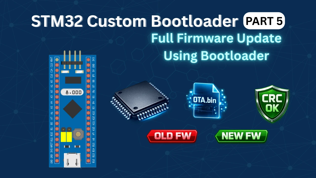
STM32 Custom Bootloader (Part 5): Implementing OTA Update
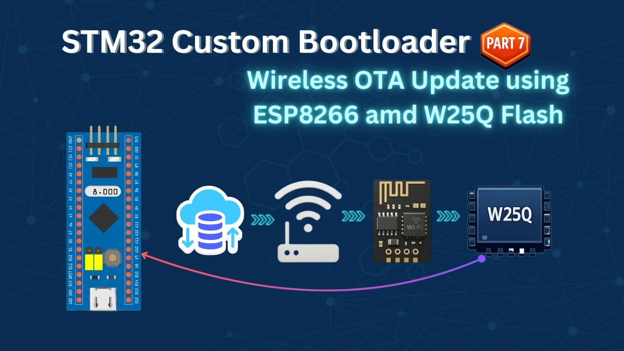
STM32 OTA Bootloader (PART 7): Wireless Firmware Update Using ESP8266 WiFi Module
STM32 Bootloader Project Download

STM32 Bootloader OTA FAQs

Subscribe
Login
0 Comments
Newest
