Updated On: April 1, 2026
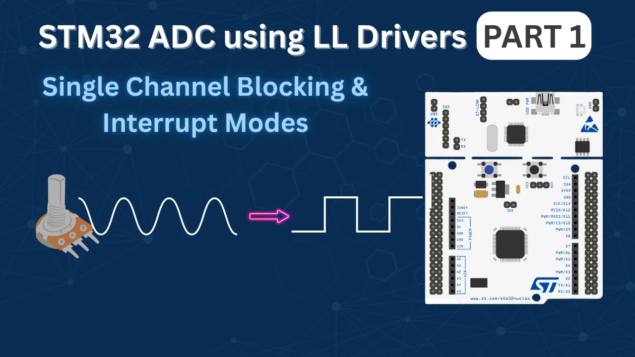
STM32 ADC Single Channel Using LL Drivers (Blocking and Interrupt Mode)
In this tutorial, we will work with the STM32 ADC using LL drivers. We will configure the ADC using STM32CubeMX, but the main logic will be written manually in STM32CubeIDE. This approach helps us understand what is really happening inside the ADC instead of hiding everything behind HAL functions.
This tutorial is Part 1 of the STM32 ADC series using LL drivers. In this part, we will focus only on single channel ADC with blocking and interrupt modes. DMA and timer-triggered ADC will be covered in later tutorials.
We will start with a single ADC channel. First, we will read the ADC value using blocking mode. This method is easy to understand and is useful for learning how the ADC works internally. After that, we will move to interrupt mode, where the CPU does not need to wait for the conversion to finish.
STM32 ADC Single Channel: How It Works
Before writing any code, we need to understand how the STM32 ADC works internally. This will help us understand why certain flags are used and why blocking and interrupt modes behave differently. I will keep this section simple and focused only on what is required for this tutorial.
Single Channel ADC Concept
In single channel ADC mode, the ADC is configured to read only one analog input pin. The ADC takes the voltage present on that pin and converts it into a digital value.
Since only one channel is used, the ADC performs one conversion every time it is triggered. There is no scanning of multiple channels and no sequence involved. This makes single channel ADC easier to understand and ideal for learning.
In this tutorial, we will trigger the ADC using software. This means we will manually start the conversion whenever we want to read the ADC value.
What Is ADC Conversion and EOC Flag
When the ADC starts, it performs a conversion. During this time, the ADC samples the input voltage and converts it into a digital value.
Once the conversion is finished, the ADC sets a flag called EOC (End of Conversion). This flag tells us that the conversion is complete and the ADC data register now contains a valid value.
In blocking mode, we continuously check this EOC flag and wait until it becomes set. Once the flag is set, we read the ADC value.
In interrupt mode, the ADC generates an interrupt when the EOC flag is set. The CPU does not need to wait. The ADC interrupt handler runs automatically and reads the ADC value.
EOC vs EOS (End of Sequence)
STM32 ADC also has another flag called EOS (End of Sequence).
EOS is used when multiple channels are configured in scan mode. In that case, the ADC converts all channels one by one. When the last channel conversion is finished, the EOS flag is set.
For single channel ADC:
- EOC and EOS happen at the same time
- There is only one conversion, so one sequence
For multi-channel ADC:
- EOC is set after each channel
- EOS is set after all channels are converted
In this tutorial, we are using only a single channel. So we will mainly work with the EOC flag.
Blocking vs Interrupt Mode
Blocking and interrupt modes differ in how the CPU waits for the ADC conversion to finish.
In blocking mode, the CPU starts the ADC and then waits in a loop until the EOC flag is set. The CPU does nothing else during this time. This method is simple but not efficient.
In interrupt mode, the CPU starts the ADC and continues running other code. When the ADC conversion finishes, an interrupt is generated. The ADC value is then handled inside the interrupt handler.
Blocking mode is good for simple tests and learning. Interrupt mode is better when the CPU needs to do other tasks while the ADC is converting.
STM32CubeMX Configuration for ADC Single Channel
In this section, we will configure the ADC using STM32CubeMX. We will only do the basic configuration here. The idea is to let CubeMX handle the peripheral setup, while we write the ADC logic ourselves using LL drivers in STM32CubeIDE.
STM32 Clock Configuration
Before generating the project, we must configure the system clock. Open the Clock Configuration tab in CubeMX.
For the STM32F446RE, we will use the 8 MHz external crystal in bypass mode. This is the default clock source on the Nucleo board. The bypass mode uses the clock from the on-board ST-Link MCU.
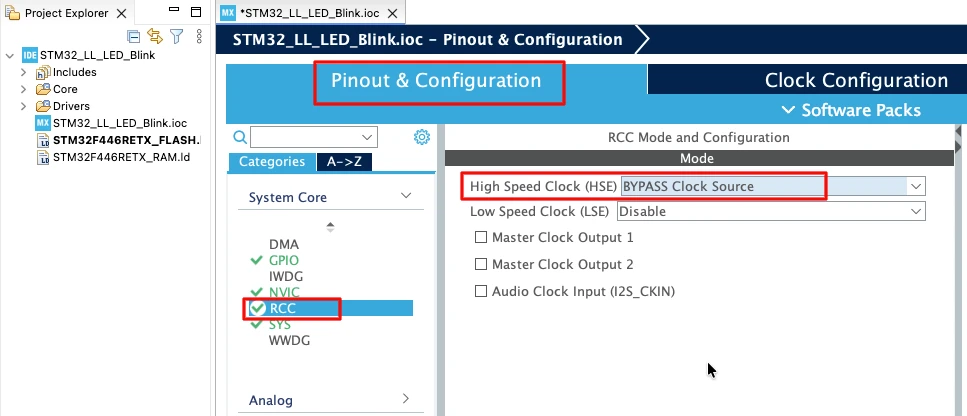
We will feed this into the PLL and run the system at 180 MHz, which is the maximum frequency for this MCU.
The image below shows the complete PLL and clock configuration used to achieve 180 MHz.
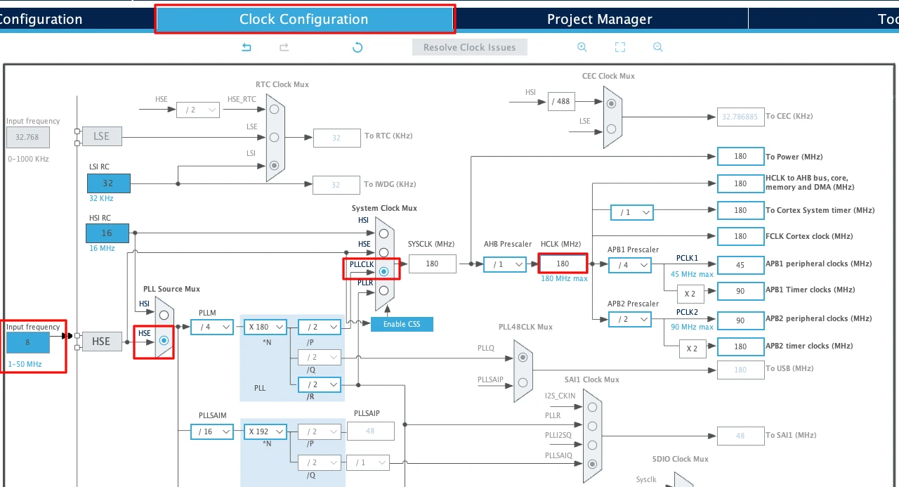
This fast system clock ensures accurate delays and smooth blinking using LL drivers. The SysTick timer will also run from this 180 MHz system clock, which becomes important in the delay functions we will use later.
Note for STM32F103C8
This MCU uses an 8 MHz external crystal as well, but its maximum frequency is 72 MHz. If you are using the Blue Pill, configure the PLL so that the final system clock is 72 MHz.
ADC Configuration
I am going to use the ADC1 for this tutorial. The image below shows the ADC configuration for STM32F446RE.
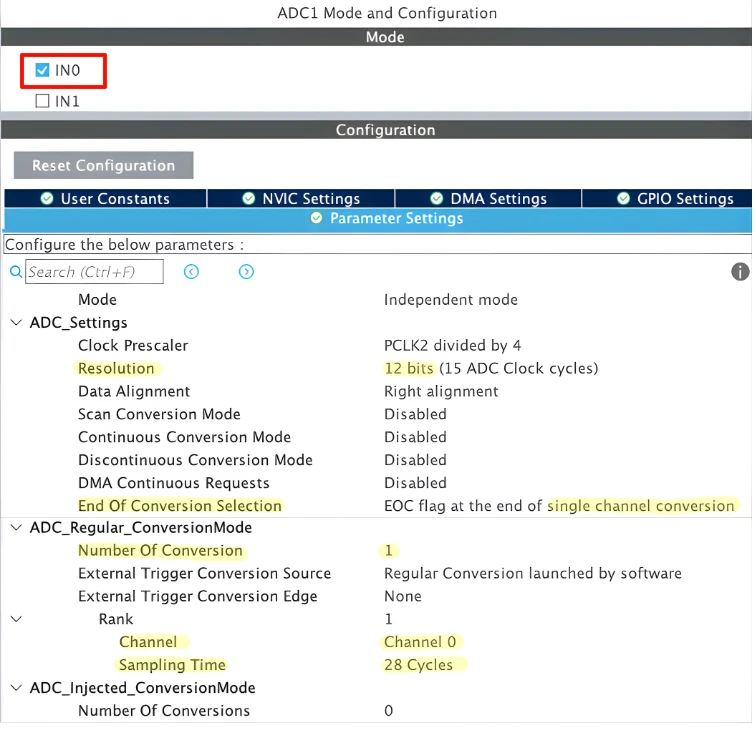
We will discuss everything else is detail as we proceed through this ADC series. For now, let’s just understand things in short, and focus on the things that we need for this tutorial.
Resolution
This option selects the ADC resolution. Higher resolution gives more accurate readings but slightly increases conversion time. In most cases, 12-bit resolution is used.
- STM32F446 supports 12-bit, 10-bit, 8-bit, and 6-bit resolution. It has an option in the CubeMX to configure the resolution.
- STM32F103C8 does not have any option to configure the resolution. It supports 12-bit by default and it is fixed.
In 12-bit resolution, the ADC will output values between 0 to 4095 (212-1).
End of Conversion Selection (EOC Selection)
This decides when the EOC flag is set.
It can be set after each conversion (EOC) or after the entire sequence (EOS). For single channel ADC, both behave the same. For multi-channel ADC with DMA, this setting becomes very important.
Sampling Configuration
Since we are using only one ADC channel, the rank is set to 1. This means the ADC will convert only this channel whenever a conversion is started.
The channel is connected to a potentiometer, which is usually noisy. To get a stable and accurate ADC value, we keep the sampling time higher, around 30 ADC clock cycles. A longer sampling time helps the ADC read the input voltage more reliably.
This slightly increases the conversion time, but for a single channel ADC it is not a problem and gives better results.
Data Alignment
This decides how the ADC data is stored in the data register.
Right alignment is commonly used because the ADC value appears directly as a normal number. Left alignment is mainly useful when working with lower resolutions.
Scan Conversion Mode
Scan mode allows the ADC to convert multiple channels in sequence.
For single channel ADC, scan mode must be disabled. We will enable scan mode only when working with multiple ADC channels.
Continuous Conversion Mode
When continuous conversion mode is enabled, the ADC keeps converting continuously after the first start command. In this mode, the ADC runs as fast as it can. This is useful for high-speed sampling but can overload the CPU if interrupts are used.
For this tutorial, we will keep continuous mode disabled and trigger the ADC manually.
Discontinuous Conversion Mode
Discontinuous mode is used only with scan mode.
It allows the ADC to convert a fixed number of channels per trigger instead of the full sequence. This mode is useful in advanced applications but is not needed for single channel ADC.
DMA Continuous Requests
This option allows the ADC to generate DMA requests continuously.
It is used only when ADC DMA mode is enabled. Since we are not using DMA in this tutorial, this option will not affect our configuration.
Note for STM32F103C8:
STM32F103C8 does not let us configure the ADC Resolution, it uses 12-bit by default.
It also does not let us choose the End Of Conversion Flag. By default the End Of Conversion is set to End Of Sequence (EOS). In single channel mode, this does not matter as the sequence itself consists of single channel only.
Enable Interrupt
To use ADC interrupt mode, we must enable the ADC interrupt in NVIC.
Go to the NVIC Settings section inside the ADC configuration. Enable the ADC global interrupt. You can leave the priority at the default value.
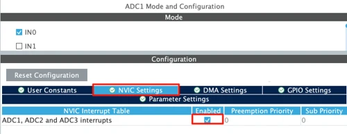
Even though we will start with blocking mode, enabling the interrupt here allows us to use interrupt mode later without changing CubeMX settings again.
Enabling the LL Drivers
Now open Project Manager → Advanced Settings. Enable LL Drivers for all peripherals. This ensures CubeMX generates clean, lightweight LL code.
The image below shows the LL driver selection in CubeMX.
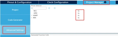
This step is important because CubeMX uses HAL by default. Switching to LL gives you direct control over the GPIO registers.
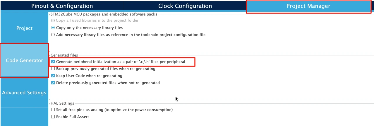
Next, go to Code Generator and select “Generate Peripheral Initialization as a pair of .c/.h files per peripheral”. This will generate a separate source files for all the peripherals we will use in a project.
STM32 ADC Blocking Mode Using LL Drivers
Now we will read the ADC value using the blocking (polling) method. In this mode, the CPU waits until the ADC conversion is completed. This approach is simple and easy to understand, which makes it a good starting point for learning how the ADC works.
ADC Initialization Using LL
Before starting the conversion, the ADC must be enabled. In blocking mode, we enable the ADC just before starting the conversion and disable it again after reading the value.
LL_ADC_Enable(ADC1);This powers up the ADC and makes it ready for conversion. Since we are reading the ADC occasionally, enabling and disabling it inside the function is acceptable for this example.
Starting ADC Conversion
Once the ADC is enabled, we start the conversion using a software trigger.
LL_ADC_REG_StartConversionSWStart(ADC1);This tells the ADC to start converting the configured channel. At this point, the ADC samples the input voltage and begins the conversion process.
Reading ADC Value Using Polling
After starting the conversion, we wait until the conversion is finished. This is done by continuously checking the EOC flag.
while (!LL_ADC_IsActiveFlag_EOCS(ADC1));This loop blocks the CPU until the ADC sets the EOCS (End of Conversion Sequence) flag. Once the flag is set, the ADC data register contains a valid result.
We then read the ADC value and disable the ADC.
uint16_t val = LL_ADC_REG_ReadConversionData12(ADC1);
LL_ADC_Disable(ADC1);Finally, the converted value is returned to the caller.
Complete Blocking Mode Example
uint16_t ADC_LL_ReadBlocking(void)
{
	/* Enable the ADC */
	LL_ADC_Enable(ADC1);

  /* Start conversion */
  LL_ADC_REG_StartConversionSWStart(ADC1);

  /* Wait for end of conversion */
  while (!LL_ADC_IsActiveFlag_EOCS(ADC1));

  /* Read ADC value */
  uint16_t val = LL_ADC_REG_ReadConversionData12(ADC1);

  /* Disable the ADC */
  LL_ADC_Disable(ADC1);

  return val;
}In the main loop, we call this function, print the ADC value using USART, and add a small delay.
while (1)
{
	uint16_t adcVal = ADC_LL_ReadBlocking();
	printf("%u\n", adcVal);
	LL_mDelay(100);
}
Note:
On STM32F103C8, the ADC does not have the EOCS flag. Instead, it provides only the EOS (End of Sequence) flag.
So, for STM32F103C8, the polling condition must be changed to:
while (!LL_ADC_IsActiveFlag_EOS(ADC1));while (!LL_ADC_IsActiveFlag_EOS(ADC1));
Since we are using a single channel, EOS works the same way as EOC in this case.
Output
The gif below shows the ADC output on the serial terminal while the potentiometer is rotated.

As the potentiometer knob is turned, the input voltage applied to the ADC pin changes. Because of this, the ADC value printed on the serial terminal also changes in real time.
When the potentiometer is at the minimum position, the ADC value is close to 0. As the knob is rotated towards the maximum position, the ADC value gradually increases and reaches close to 4095 for a 12-bit ADC.
The smooth change in values confirms that the ADC is working correctly in blocking mode and the analog input is being sampled properly.
STM32 ADC Interrupt Mode Using LL Drivers
After blocking mode, we move to interrupt-based ADC. In this approach, the CPU does not wait for the ADC to finish. Instead, the ADC notifies the CPU using an interrupt when the conversion is complete. This makes the code cleaner and more efficient.
Why Use ADC Interrupt Mode
In blocking mode, the CPU stays stuck in a while loop until the ADC finishes conversion. This wastes CPU time.
In interrupt mode, the ADC works in the background. The CPU continues executing other code and gets notified only when the ADC result is ready. This is useful when your application has other tasks to handle.
Enabling ADC Interrupt
Before starting the ADC conversion, we must enable the ADC End of Conversion interrupt.
volatile uint16_t adcData = 0;
volatile uint8_t adc_ready = 0;These variables are declared as volatile because they are modified inside the interrupt handler.
void ADC_LL_StartIT(void)
{
	adc_ready = 0;   // clear old flag

	LL_ADC_EnableIT_EOCS(ADC1);   // enable ADC EOC interrupt
	LL_ADC_Enable(ADC1);          // enable ADC
	LL_ADC_REG_StartConversionSWStart(ADC1); // start conversion
}Here, we clear the old status flag, enable the ADC interrupt, enable the ADC itself, and then start the conversion using a software trigger.
ADC Interrupt Handler Explanation
When the ADC finishes the conversion, it triggers an interrupt. The ADC interrupt handler is executed automatically.
void ADC1_InterruptHandler(void)
{
	if (LL_ADC_IsActiveFlag_EOCS(ADC1))
	{
		adcData = LL_ADC_REG_ReadConversionData12(ADC1);
		adc_ready = 1;

		LL_ADC_ClearFlag_EOCS(ADC1);
	}
}Inside the handler, we first check the EOCS flag. This confirms that the conversion is complete.
We then read the ADC value, store it in adcData, and set a software flag adc_ready. This flag tells the main loop that a new ADC value is available.
Finally, we clear the EOCS flag to prepare for the next conversion.
Main Loop Using ADC Interrupt
int main(void)
{
  ....
  ....
	ADC_LL_StartIT();

	while (1)
	{
		if (adc_ready == 1)
		{
			printf("%u\n", adcData);
			ADC_LL_StartIT();
		}

		LL_mDelay(100);
	}
}In the main loop, we simply check the adc_ready flag. When it becomes 1, we print the ADC value and start the next conversion.
The CPU is free to do other tasks while the ADC conversion happens in the background.
*Important Notes*
STM32F103C8:
The STM32F103C8 does not have the EOCS flag. Instead, it uses the EOS (End of Sequence) flag.
So for F103C8, use LL_ADC_IsActiveFlag_EOS() and clear the EOS flag instead.
Interrupt Handler Declaration:
The function void ADC1_InterruptHandler(void) must be declared as extern in the stm32xx_it.c file. This ensures that the linker correctly connects your interrupt handler with the ADC interrupt vector.
extern void ADC1_InterruptHandler(void);

void ADC_IRQHandler(void)
{
  /* USER CODE BEGIN ADC_IRQn 1 */
	ADC1_InterruptHandler();
  /* USER CODE END ADC_IRQn 1 */
}Output
The gif below shows the ADC values printed on the serial terminal using interrupt mode.
As the potentiometer is rotated, the ADC values change accordingly. This confirms that the ADC interrupt is working correctly and the conversion result is received without blocking the CPU.
Tips and Troubleshooting for STM32 ADC Using LL Drivers
This section highlights common tips and issues you may face while working with STM32 ADC in blocking and interrupt modes. Most ADC problems come from small configuration or logic mistakes, so these points are worth checking.
Tips
- Use a longer sampling time for potentiometers, sensors, and high-impedance sources. This gives more stable and accurate readings.
- Prefer interrupt mode over blocking mode once you move beyond basic testing. It keeps the CPU free for other tasks.
- Always declare shared variables between ISR and main code as volatile.
- Clear EOC / EOCS / EOS flags after reading ADC data. Leaving flags uncleared can cause repeated interrupts.
- Start with single channel, single conversion before enabling scan or continuous modes. This makes debugging much easier.
- Let CubeMX configure clocks and GPIOs, but write ADC logic yourself using LL drivers to understand how the ADC really works.
Troubleshooting Common Problems
- ADC value always zero or fixed
Check if the ADC pin is configured in analog mode and connected to the correct channel. - ADC interrupt fires only once
Make sure you restart the conversion after handling the interrupt and clear the EOC/EOS flag properly. - CPU stuck or code not running
In blocking mode, confirm that you are checking the correct flag (EOCSorEOS) for your MCU. - Very noisy ADC values
Increase the sampling time and add a small delay between conversions. - No interrupt at all
Ensure the ADC interrupt is enabled in NVIC and that the ISR function name matches the vector table. - Code works on one STM32 but not another
Different STM32 families use different ADC flags and features. Always verify the reference manual for your specific MCU.
Following these tips and checks will help you quickly identify ADC issues and build reliable STM32 ADC applications using LL drivers.
Conclusion
In this tutorial, we learned how to use STM32 ADC in single channel mode using LL drivers. We started by understanding how ADC works internally, then configured the ADC using STM32CubeMX. After that, we implemented ADC reading using blocking (polling) mode and interrupt mode, and saw how to read and print the ADC values on a serial terminal.
These methods are useful for learning ADC fundamentals and for simple applications where only one analog signal is required. Blocking mode helps beginners understand the ADC flow, while interrupt mode shows how to write more efficient and non-blocking code. In the next part, we will move to multi-channel ADC, where we will scan multiple inputs and understand how ADC sequences work in real applications.
Browse More STM32 LL Tutorials
STM32 UART using LL Drivers (Part 1): Transmit using Polling Mode
STM32 UART using LL Drivers (Part 2): Transmit using Interrupt & DMA
STM32 UART using LL Drivers (Part 3): Receive Data in Blocking Mode
STM32 UART using LL Drivers (Part 4): Receive Data in Interrupt Mode
STM32 UART using LL Drivers (Part 5): Receive Using DMA (Normal and Circular Mode)
STM32 ADC Using LL Drivers (Part 2): Multiple Channels using DMA Mode
STM32 I2C using LL Drivers (Part 1): I2C Scanner to Detect I2C Devices with STM32CubeMX
STM32 LL Project Download
STM32 LL ADC FAQs

Subscribe
Login
0 Comments
Newest
