
Updated On: April 1, 2026
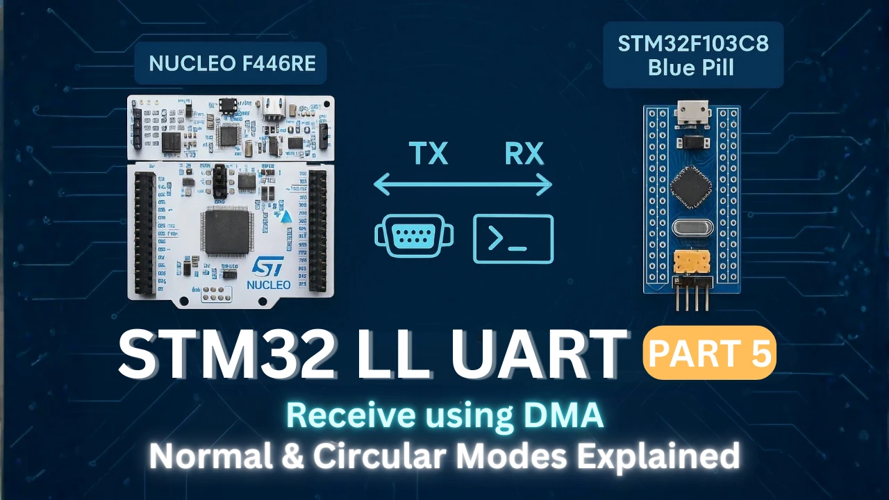
STM32 UART Receive Using DMA (Normal and Circular Mode) with LL Drivers
DMA is the best way to receive high-speed UART data on STM32. It allows the USART peripheral to move data directly into memory without using the CPU.
In the previous tutorial, we learned how to receive UART data using interrupts with LL drivers. That method works well for small data. But when the data rate increases, the CPU starts missing bytes.
This is where DMA (Direct Memory Access) becomes very powerful. With DMA, the USART hardware pushes data into RAM automatically. The CPU only wakes up when a block of data is ready. This makes the system fast and very reliable.
In this tutorial, we will learn how to use:
- UART RX using DMA in Normal mode
- UART RX using DMA in Circular mode
Both will be implemented using STM32 LL drivers.
We will also learn how to safely process the data without corruption. The technique used here is the same one used in many real-world products.
STM32 UART DMA Receive Overview
Before we start writing code, it is important to understand how UART DMA receive actually works inside the STM32. This section explains the basic idea in simple words. It also shows why DMA is much better than using RX interrupts when the data rate becomes high.
What is UART DMA?
UART DMA means that the USART peripheral sends received data directly to RAM using the DMA controller. The CPU is not involved in moving each byte.
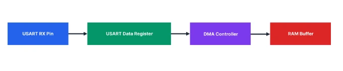
When a new byte arrives on the UART RX pin, the USART puts it into its data register. At the same time, it sends a request to the DMA controller. The DMA then copies that byte into a memory buffer.
This process continues for every received byte.
So the data flows straight into memory without using CPU instructions. The CPU only gets involved when the DMA tells it that a block of data is ready.
This is why UART DMA is very fast and very efficient.
Why DMA is Better than RX Interrupt
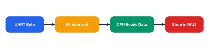
In RX interrupt mode, the CPU runs an interrupt for every received byte. At low speed, this works well. But when data comes quickly, the CPU starts spending too much time inside the UART ISR.
With DMA, this problem goes away. Here is the difference in simple terms.
- RX interrupt: CPU handles every byte.
- DMA: CPU handles only completed blocks.
In RX interrupt mode, the flow looks like this:
In DMA mode, it becomes:
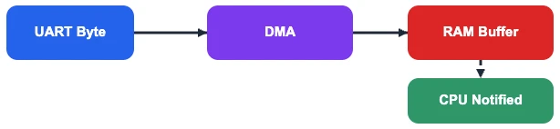
So instead of thousands of interrupts per second, the CPU gets only a few DMA interrupts. This makes the system faster and more stable, even at high baud rates.
This is why DMA is used in real applications like GPS, ESP AT commands, Modbus, and data loggers.
Difference Between Normal and Circular Mode
UART RX DMA has two important modes: Normal mode and Circular mode. Each one is used for a different type of data.
Normal mode is used when you know how many bytes you will receive. The DMA stops automatically after receiving that many bytes.
Example uses:
- Modbus frames
- GPS packets
- OTA data blocks
Circular mode is used when data never stops. The DMA keeps filling the buffer again and again in a loop.
Example uses:
- Serial console
- ESP AT commands
- Debug logs
- Continuous data streams
In circular mode, the DMA buffer behaves like a ring. When it reaches the end, it starts again from the beginning. The CPU reads the data while the DMA keeps writing.
This makes circular mode perfect for real-time UART streaming.
STM32 UART RX DMA Hardware Flow
To use UART DMA correctly, we must understand how the hardware works inside the STM32. The USART and DMA do most of the work by themselves. The CPU only controls and supervises the process.
This section explains how the data moves from the UART pin to RAM without using the CPU for every byte.
How USART Triggers DMA
When a byte arrives on the UART RX pin, the USART stores it in its data register. This action sets an internal flag inside the USART.
If RX DMA is enabled, the USART sends a request to the DMA controller instead of raising an interrupt.
So the flow becomes:
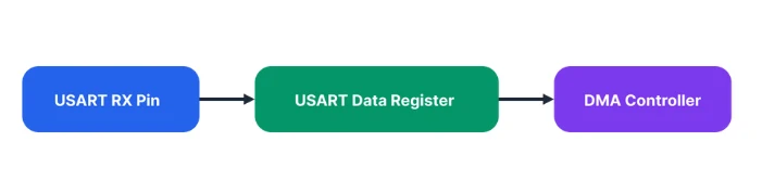
The USART does not wait for the CPU. It directly asks the DMA to fetch the data. This happens for every received byte. This is why UART DMA can work at very high speeds without losing data.
How DMA Moves Data to RAM
When the DMA controller receives a request from the USART, it performs a simple operation. It reads one byte from the USART data register and writes it to the RAM buffer.
The DMA also updates two internal pointers:
- The current memory address
- The remaining data length
A small code example shows what the DMA is doing internally:
*memory_pointer = USART_DR;
memory_pointer++;
remaining_length--;This process repeats for every received byte. No CPU instructions are executed during this copy.
When the buffer is half full or completely full, the DMA raises an interrupt. This is how the CPU knows that data is ready.
What Happens Without CPU Involvement
The most important advantage of UART DMA is that the CPU is not part of the data path.
The CPU does not:
- Read UART registers
- Store bytes into arrays
- Handle interrupts for every byte
Instead, the CPU only reacts when a block of data is ready.
So the real data flow looks like this:
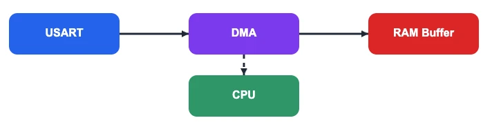
This separation makes the system very fast and very stable. Even when a long stream of data is coming, the CPU can continue running other tasks.
This is why DMA is the preferred way to handle UART in high-speed and real-time applications.
UART DMA Setup in STM32CubeMX (LL Drivers)
Inside CubeMX, the DMA configuration appears similar for both the STM32F103C8 and STM32F446RE MCUs. However, there are important differences at the DMA hardware level, and these differences affect how the DMA must be programmed in firmware.
Enabling USART2 DMA for Nucleo-F446
Nucleo boards come with an onboard ST-Link debugger that also provides a Virtual COM Port (VCP). This VCP is connected internally to USART2, making it a great choice for UART communication without additional hardware.
The image below shows the USART2_RX DMA enabled for Nucleo-F446RE.
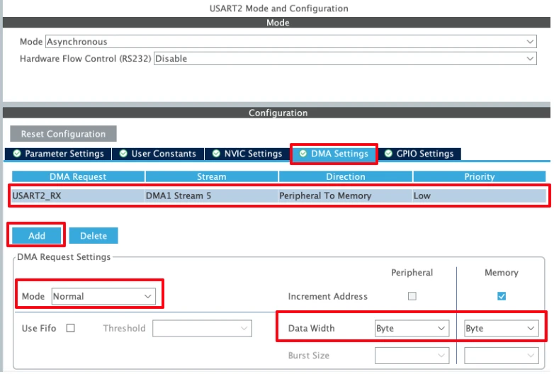
Click Add to add the DMA request and select USART_RX to enable the DMA in RX mode.
1. DMA Request selection
The DMA Request is set to USART2_RX, which means this DMA stream will be triggered automatically whenever USART2 needs to receive data. This links the DMA controller directly to the USART2 Receive register.
2. DMA Stream and Direction
- DMA1 Stream 5 is selected for USART2 RX (as per STM32F4 DMA mapping).
- Direction: Peripheral to Memory
This is essential for UART reception, because data flows from the USART data register to a memory buffer (RAM).
3. DMA Mode
In Normal mode, the DMA transfers the specified number of bytes and then stops automatically. Whereas in Circular Mode, the DMA continues to transfer data.
We will test both modes, starting with the Normal Mode first.
4. Increment Address settings
- Peripheral increment: Disabled
The USART data register address must remain fixed. - Memory increment: Enabled
This allows the DMA to write consecutive bytes from the receive buffer to the memory.
5. Data Width
- Peripheral data width: Byte
- Memory data width: Byte
UART receives data one byte at a time, so both widths must be set to Byte. Any mismatch here can lead to corrupted or failed transmissions.
6. Priority
- Priority: Low
UART transmission usually does not require high priority. This can be increased if DMA contention exists with other peripherals.
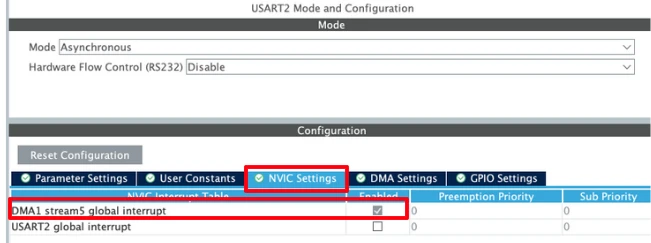
After enabling the DMA request, the DMA interrupt is enable automatically. You can confirm it in the NVIC Tab as shown in the image below.
Enabling USART1 Interrupt for STM32F103C8
The DMA configuration will remain pretty much the same as we saw in Nucleo-F446. The image below shows the DMA configuration for STM32F103C8.
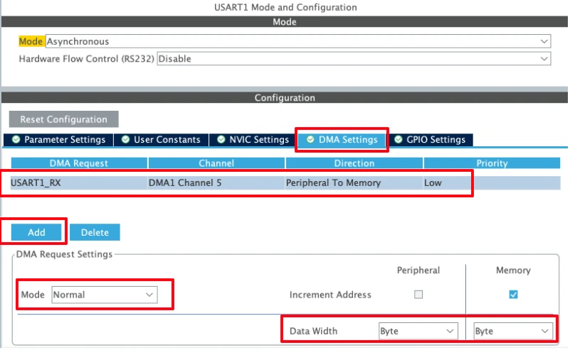
Click Add to add the DMA request and select USART_RX to enable the DMA in RX mode.
- Make sure the Direction is from Peripheral to Memory as the STM32 will receive the data from UART Peripheral.
- The DMA Mode can be Normal or Circular. We will test the Normal Mode first and then Circular mode later in this tutorial.
- The data width must be set to Byte.
After enabling the DMA request, the DMA interrupt is enable automatically. You can confirm it in the NVIC Tab as shown in the image below.
The configuration remains the same as that of the Nucleo-F446. However, note that in this case the DMA uses channels, whereas the Nucleo board uses streams. This difference arises from the underlying DMA architecture of the MCU family and affects how the DMA is configured and programmed in firmware.
UART RX DMA Normal Mode (LL Drivers)
The DMA Normal mode is ideal when you know exactly how many bytes you expect from the UART. In this mode, the DMA copies a fixed number of bytes from the USART data register to RAM and then stops. The CPU is notified only when the transfer is complete.
This makes it perfect for packet-based protocols, AT command responses, Modbus frames, or any fixed-length UART message.
The flow in Normal mode is:
RX Buffer Setup
First, we define the buffer where DMA will store incoming bytes:
#define RX_BUF_SIZE  10
uint8_t Rx_Buffer[RX_BUF_SIZE];Here, the DMA will receive exactly 10 bytes before raising an interrupt. Using a small, fixed-size buffer helps prevent overrun and keeps the system simple.
UART Send Function
We need a function to transmit data back to the PC for debugging. I have already covered in detail: STM32 UART Transmit using LL Drivers. Here’s a minimal blocking implementation:
void uart_send(char *data)
{
while (*data)
{
while (!LL_USART_IsActiveFlag_TXE(USART2)); // Wait until TX buffer is empty
LL_USART_TransmitData8(USART2, *data++); // Transmit next byte
}
while (!LL_USART_IsActiveFlag_TC(USART2)); // Wait for final transmission to complete
}Explanation:
LL_USART_IsActiveFlag_TXEensures the previous byte has been moved to the shift register.LL_USART_TransmitData8writes the next byte to the USART data register.LL_USART_IsActiveFlag_TCensures the last byte is fully transmitted before returning.
This is simple, reliable, and perfect for debugging.
Processing the Received Data
Once the DMA finishes transferring the buffer, we need to format and print it:
void ProcessData(uint8_t *buffer, size_t len)
{
char txBuf[len + 30];
strcpy(txBuf, "Data Received is: ");
strncat(txBuf, (char *)buffer, len);
strcat(txBuf, "\r\n");
uart_send(txBuf);
}Explanation:
strcpyandstrncatbuild a readable string from the DMA buffer.- The function does not access the DMA hardware directly; it simply processes the data already in RAM.
- Sending via
uart_send()is blocking, but safe because Normal mode DMA stops automatically and won’t overwrite the buffer while printing.
I’m prepending the string "Data Received is: " to the data received from the PC. This makes it easy to distinguish between what was sent by the computer and what the STM32 is sending back.
Starting UART RX DMA
This function configures and starts DMA reception:
void UART_DMA_Start(uint8_t *buffer, size_t len)
{
LL_DMA_DisableStream(DMA1, LL_DMA_STREAM_5); // Disable DMA stream first
while (LL_DMA_IsEnabledStream(DMA1, LL_DMA_STREAM_5)); // Wait until fully disabled
LL_DMA_SetPeriphAddress(DMA1, LL_DMA_STREAM_5, LL_USART_DMA_GetRegAddr(USART2)); // USART DR
LL_DMA_SetMemoryAddress(DMA1, LL_DMA_STREAM_5, (uint32_t)buffer); // RAM buffer
LL_DMA_SetDataLength(DMA1, LL_DMA_STREAM_5, len); // Number of bytes
LL_USART_EnableDMAReq_RX(USART2); // Connect USART RXNE to DMA request
LL_DMA_EnableIT_TC(DMA1, LL_DMA_STREAM_5); // Enable Transfer Complete interrupt
LL_DMA_EnableStream(DMA1, LL_DMA_STREAM_5); // Enable the DMA stream
}Explanation:
- Disable the DMA stream before changing addresses and lengths, STM32 F4 hardware requires this.
- Set peripheral address to
USART2->DR, so every RX byte is automatically read by DMA. - Set memory address to the buffer in RAM.
- Set data length to the number of bytes to receive.
- Enable USART DMA request, linking RXNE to the DMA controller.
- Enable Transfer Complete interrupt so the CPU knows when the buffer is full.
- Enable the DMA stream to start reception.
DMA Transfer Complete Interrupt
The DMA stream raises a Transfer Complete (TC) interrupt when the buffer is filled:
void USART_DMA_IRQHandler(void)
{
if (LL_DMA_IsActiveFlag_TC5(DMA1))
{
LL_DMA_ClearFlag_TC5(DMA1); // Clear the TC flag
ProcessData(Rx_Buffer, RX_BUF_SIZE); // Process received data
UART_DMA_Start(Rx_Buffer, RX_BUF_SIZE); // Restart DMA for next packet
}
}Explanation:
LL_DMA_IsActiveFlag_TC5checks if the DMA stream finished transferring all bytes.LL_DMA_ClearFlag_TC5clears the interrupt so the next TC event can trigger.ProcessDataprocesses the received bytes safely from RAM.UART_DMA_Startre-arms DMA for the next packet, keeping the reception continuous.
Starting Reception in Main
In main(), we simply start DMA once:
UART_DMA_Start(Rx_Buffer, RX_BUF_SIZE);After that, all reception is automatic, and the CPU only processes full packets.
Output
The image below shows the UART terminal printing the received packet after DMA transfer completes.
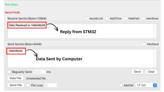
You can see above, when the PC sends exactly 10 characters “HelloWorld”, the STM32 prints “Data Received is: HelloWorld”.
This confirms that UART RX DMA Normal mode is working correctly with LL drivers.
What changes in STM32F103C8?
As shown in the configuration, the STM32F103C8 relies on DMA channels instead of streams. Hence, the only modification needed is to switch from stream-based DMA handling to channel-based handling.
Below is the UART_DMA_Start() function to configure the DMA1 Channel5 in the STM32F103C8T6. This is the only function where we need to make the changes.
void UART_DMA_Start(uint8_t *buffer, size_t len)
{
LL_DMA_DisableChannel(DMA1, LL_DMA_CHANNEL_5); // Diable DMA
while (LL_DMA_IsEnabledChannel(DMA1, LL_DMA_CHANNEL_5));
LL_DMA_SetPeriphAddress(DMA1, LL_DMA_CHANNEL_5, LL_USART_DMA_GetRegAddr(USART1)); // Set peripheral Data Register address
LL_DMA_SetMemoryAddress(DMA1, LL_DMA_CHANNEL_5, (uint32_t)buffer); // Set Memory address as the buffer
LL_DMA_SetDataLength(DMA1, LL_DMA_CHANNEL_5, len); // Set data length
LL_USART_EnableDMAReq_RX(USART1); // Enable USART RX via DMA
LL_DMA_EnableIT_TC(DMA1, LL_DMA_CHANNEL_5); // Enable Transfer Complete Interrupt
LL_DMA_EnableChannel(DMA1, LL_DMA_CHANNEL_5); // Enable DMA
}Apart from changing LL_DMA_STREAM_5 to LL_DMA_CHANNEL_5, there is essentially no other modification required. Also note that the functions LL_DMA_EnableChannel() and LL_DMA_DisableChannel() are used instead of their stream-based counterparts.
Note:
I have attached the F103C8 project in the Final project file. You can download the projects for both F446 and F103 from the link at the bottom of this post.
UART RX DMA Circular Mode (LL Drivers)
The DMA Circular mode is used when data arrives continuously and the total length is unknown. Instead of stopping after a fixed number of bytes, the DMA keeps filling the buffer in a loop, automatically restarting from the beginning when the end is reached.
This is ideal for:
- Continuous serial logs
- Streaming GPS data
- Serial consoles
- Any high-speed, indefinite-length UART stream
In Circular mode, the CPU never handles individual bytes in real time. Instead, it processes data from a software buffer at its own pace.
Why Circular Mode is Needed
In high-speed or continuous data streams, Normal mode is insufficient because:
- Normal mode stops when the buffer is full
- CPU must restart DMA each time
- Fast streams can overflow the buffer before CPU can react
Circular mode solves this:
The hardware automatically wraps around the DMA buffer, so no data is lost, and the CPU can process it in blocks or character-by-character.
CubeMX Settings for Circular Mode
I have already explained the UART configuration in the STM32CubeMX Configuration above. The only change we need to make is: configure the DMA in Circular Mode.
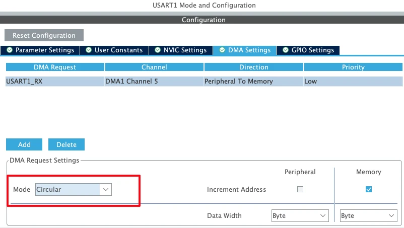
Other then configuring the DMA in circular mode, the rest of the configuration will remain the same as the Normal Mode.
Circular RX Buffer
We configure a small DMA hardware buffer and a larger software buffer:
#define RX_BUF_SIZE  10
uint8_t Rx_Buffer[RX_BUF_SIZE];
#define SW_BUF_SIZE 64
uint8_t swBuf[SW_BUF_SIZE];
volatile uint16_t swHead = 0;
static uint16_t lastPos = 0;Rx_Bufferis the DMA hardware buffer (small, fast)swBufis a software circular buffer where CPU processes dataswHeadpoints to the next free location in software bufferlastPostracks the last processed byte
This separation allows safe processing without blocking the DMA.
Half Transfer and Full Transfer Interrupts
Circular mode allows DMA to trigger two interrupts:
- Half-Transfer (HT) → when the first half of
Rx_Bufferis filled - Transfer Complete (TC) → when the second half of
Rx_Bufferis filled
ISR example:
void USART_DMA_IRQHandler(void)
{
    if (LL_DMA_IsActiveFlag_HT5(DMA1))
    {
        LL_DMA_ClearFlag_HT5(DMA1);
        CopyToSoftwareBuffer(&Rx_Buffer[0], RX_BUF_SIZE/2);
    }

    if (LL_DMA_IsActiveFlag_TC5(DMA1))
    {
        LL_DMA_ClearFlag_TC5(DMA1);
        CopyToSoftwareBuffer(&Rx_Buffer[RX_BUF_SIZE/2], RX_BUF_SIZE/2);
    }
}Explanation:
- Each half of the DMA buffer is processed immediately after it is filled
CopyToSoftwareBuffer()moves data into the software buffer safely- DMA continues running in circular mode, therefore, no need to restart it
Safe Data Processing
CPU can process characters from the software buffer at any time:
while (lastPos != swHead)
{
    char c = swBuf[lastPos++];
    if (lastPos >= SW_BUF_SIZE) lastPos = 0;

    ProcessChar(c);
}Explanation:
lastPoskeeps track of processed bytesswHeadtracks new data added by DMA- Processing is non-blocking, so DMA never overwrites unprocessed data
Supporting Functions
As an example of processing the data, we will write the function ProcessChar() to Transmit one character back to PC:
void ProcessChar(char c)
{
    while (!LL_USART_IsActiveFlag_TXE(USART2));
    LL_USART_TransmitData8(USART2, c);

    while (!LL_USART_IsActiveFlag_TC(USART2));
}CopyToSoftwareBuffer() function used above, Moves DMA data into software buffer safely:
void CopyToSoftwareBuffer(uint8_t *data, uint16_t len)
{
    for (uint16_t i=0; i<len; i++)
    {
        swBuf[swHead++] = data[i];
        if (swHead >= SW_BUF_SIZE)
            swHead = 0;
    }
}The function UART_DMA_Start() Configures and starts circular DMA:
void UART_DMA_Start(uint8_t *buffer, size_t len)
{
    LL_DMA_DisableStream(DMA1, LL_DMA_STREAM_5);
    while (LL_DMA_IsEnabledStream(DMA1, LL_DMA_STREAM_5));

    LL_DMA_SetPeriphAddress(DMA1, LL_DMA_STREAM_5, LL_USART_DMA_GetRegAddr(USART2));
    LL_DMA_SetMemoryAddress(DMA1, LL_DMA_STREAM_5, (uint32_t)buffer);
    LL_DMA_SetDataLength(DMA1, LL_DMA_STREAM_5, len);

    LL_USART_EnableDMAReq_RX(USART2);

    LL_DMA_EnableIT_HT(DMA1, LL_DMA_STREAM_5);
    LL_DMA_EnableIT_TC(DMA1, LL_DMA_STREAM_5);
    LL_DMA_EnableStream(DMA1, LL_DMA_STREAM_5);
}The function is very similar to how we used it in the Normal Mode. The only addition is LL_DMA_EnableIT_HT() to enable the Half-Transfer complete Interrupt.
Explanation:
- DMA fills
Rx_Buffercontinuously in circular mode - HT and TC interrupts allow safe CPU processing of each half
- The CPU never blocks the DMA, hence it is ideal for high-speed UART streams
Starting Reception
UART_DMA_Start(Rx_Buffer, RX_BUF_SIZE); // Arm DMAFrom this point, DMA runs automatically. The CPU processes characters from the software buffer inside the main loop.
Output
The image below shows STM32 continuously receiving characters from PC and echoing them back in real-time.
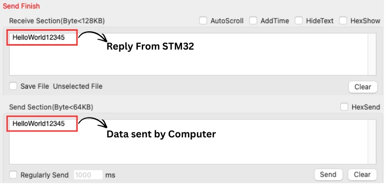
You can see above, when the PC sends “HelloWorld12345”, the STM32 received it and transmit all the charcaters back to the serial console.
- Even if data keeps coming indefinitely, DMA handles it automatically
- The CPU only reads characters from the software buffer
- No bytes are lost, thanks to circular DMA + software buffer
Preventing Data Loss in DMA Mode
DMA is powerful because it offloads the CPU, but data loss can occur if the system is not designed carefully. This section covers best practices to prevent lost bytes when using STM32 UART DMA.
Why DMA Buffers Get Overwritten
DMA works directly between the peripheral (USART) and a memory buffer. In Normal mode, DMA stops when the buffer is full. In Circular mode, it automatically wraps around.
Problems arise when:
- The CPU does not process the buffer fast enough
- Circular buffer wraps and overwrites unprocessed data
- The buffer size is too small for the data rate
Example:
If Rx_Buffer is 10 bytes and the UART sends 20 bytes before the CPU processes the first 10, the second half overwrites the first, causing data loss.
Why Not to Process Data Inside the ISR
It is tempting to process data inside Half-Transfer (HT) or Transfer Complete (TC) interrupts, but this can be dangerous:
- ISR execution blocks other interrupts
- Long processing can delay DMA handling
- High baud rates may cause buffer overruns
Best practice:
- Keep the ISR short. Only copy DMA data to a software buffer
- Do the actual processing in the main loop or a background task
Software FIFO Concept
To safely handle continuous or fast UART streams, use a software circular buffer (FIFO):
- DMA writes into a hardware buffer (Rx_Buffer)
- ISR copies data into a larger software buffer (swBuf)
- CPU reads from the software buffer at its own pace
Benefits:
- Prevents lost bytes even if CPU is busy
- Allows continuous streaming in Circular mode
- Easy to implement with simple head/tail pointers
Example diagram of the flow:
Explanation:
- DMA Normal → Rx_Buffer → CPU via TC interrupt: Shows packet-based DMA flow.
- DMA Circular → Rx_Buffer → Software FIFO → CPU: Shows continuous streaming with safe software buffer.
- HT / TC interrupts: Short ISR copies data from hardware buffer to software FIFO.
- CPU Processing: Reads from software FIFO at its own pace, hence no bytes lost.
This is the architecture we used in the Circular Mode example. It ensures safe, lossless reception, even at high UART speeds.
Conclusion
In this tutorial, we explored STM32 UART RX using DMA with LL drivers in both Normal and Circular modes. We covered how to configure DMA in CubeMX, how to set up hardware and software buffers, and how to safely handle incoming data using Half-Transfer and Transfer Complete interrupts. We also explained the difference between Normal and Circular mode, and how to use a software FIFO to prevent data loss in high-speed or continuous UART streams.
By following these techniques, you can offload the CPU from byte-by-byte UART handling, ensuring reliable and efficient data reception even at high baud rates. Whether you’re receiving fixed-length packets or continuous streams, using DMA with proper buffer management makes your STM32 applications more robust, responsive, and capable of handling demanding serial communication tasks.
Browse More STM32 LL Tutorials
STM32 LL GPIO Input and EXTI Interrupt Tutorial: Read Buttons With Low-Level Drivers
STM32 UART using LL Drivers (Part 1): Transmit using Polling Mode
STM32 UART using LL Drivers (Part 2): Transmit using Interrupt & DMA
STM32 UART using LL Drivers (Part 3): Receive Data in Blocking Mode
STM32 UART using LL Drivers (Part 4): Receive Data in Interrupt Mode
STM32 ADC Using LL Drivers (Part 1): Single Channel Blocking and Interrupt Mode
STM32 ADC Using LL Drivers (Part 2): Multiple Channels using DMA Mode
STM32 LL UART Project Download
STM32 LL UART RX DMA FAQs

Subscribe
Login
0 Comments
Newest
