Home ▸ Arduino ▸ FreeRTOS Tutorials ▸
Updated On: February 5, 2026
FreeRTOS Timing Explained on Arduino: vTaskDelay vs vTaskDelayUntil and Software Timers
Timing is one of the most important topics in FreeRTOS on Arduino Many beginners still use delay() inside tasks. This breaks multitasking and causes unstable behavior.
In this part of the Arduino FreeRTOS tutorial series, you will learn how FreeRTOS handles time. You will understand the difference between vTaskDelay() and vTaskDelayUntil(). You will also learn how to use FreeRTOS software timers for accurate and clean timing.
Table Of Contents
- Understanding Timing in FreeRTOS on Arduino
- vTaskDelay vs vTaskDelayUntil in FreeRTOS (Arduino)
- FreeRTOS Tick Rate on Arduino
- Hands-On Demo: Measuring Timing Using Serial Timestamps
- Task Using vTaskDelayUntil()
- Creating a Stable Periodic LED Task with vTaskDelayUntil()
- FreeRTOS Software Timers Explained (Arduino)
- Demo: Accurate Heartbeat LED Using FreeRTOS Software Timer
- Complete Example: All Concepts Combined
- Conclusion
Understanding Timing in FreeRTOS on Arduino
Timing plays a very important role in FreeRTOS on Arduino. Unlike a normal Arduino sketch, FreeRTOS runs multiple tasks at the same time. Each task depends on proper timing so the scheduler can switch between them smoothly.
If timing is handled incorrectly, tasks can block each other. This results in poor performance and unstable behavior. That is why understanding how FreeRTOS manages time is essential before writing real multitasking applications.
Why delay() Is Bad in an RTOS Environment
The delay() function blocks the CPU completely. When delay() runs, nothing else can execute. In a normal Arduino program, this may seem fine. But in FreeRTOS, this causes serious problems.
- Other tasks cannot run
- Task switching stops
- Real-time behavior is lost
FreeRTOS expects tasks to yield control, not block the system. Using delay() breaks the scheduler and defeats the purpose of an RTOS.
How FreeRTOS Handles Time Differently
FreeRTOS uses a tick-based timing system. A hardware timer generates periodic ticks. Each tick updates the internal scheduler clock.
When a task uses vTaskDelay() or vTaskDelayUntil():
- The task goes into a Blocked state
- The CPU becomes available for other tasks
- The scheduler decides what runs next
This approach enables:
- True multitasking
- Efficient CPU usage
- Predictable timing
FreeRTOS timing functions work with the scheduler, not against it. That is what makes FreeRTOS suitable for real-time Arduino projects.
vTaskDelay vs vTaskDelayUntil in FreeRTOS (Arduino)
FreeRTOS provides special delay functions designed for multitasking systems. These functions pause a task without blocking the CPU. However, not all delay functions behave the same way.
vTaskDelay(): Relative Delay Explained
vTaskDelay() delays a task for a relative amount of time. The delay starts when the function is called.
vTaskDelay(pdMS_TO_TICKS(1000));This means the task sleeps for 1000 ms from that point onward. If the task takes time to execute before calling vTaskDelay(), that time is added to the overall period.
As a result:
- Timing slowly shifts
- Period is not fixed
- Small delays accumulate over time
This method is fine for:
- Non-critical delays
- Simple background tasks
vTaskDelayUntil(): Absolute and Periodic Delay
vTaskDelayUntil() works differently. It delays a task until a specific tick count is reached.
vTaskDelayUntil(&lastWakeTime, pdMS_TO_TICKS(1000));Here, the delay is based on a fixed reference time. The task wakes up at exact intervals, regardless of execution time.
This makes it perfect for:
- Periodic tasks
- LED blinking
- Sensor sampling
- Communication loops
The timing stays stable and predictable.
Jitter and Why Periodic Tasks Matter
Jitter means variation in task execution time. In real-time systems, jitter can cause serious problems.
Using vTaskDelay():
- Execution time adds uncertainty
- Timing drifts slowly
Using vTaskDelayUntil():
- No drift
- Constant period
- Minimal jitter
For periodic tasks, consistency matters more than speed. That is why vTaskDelayUntil() is the preferred choice in FreeRTOS on Arduino.
FreeRTOS Tick Rate on Arduino
FreeRTOS does not measure time in milliseconds directly. Instead, it uses a system clock called the tick. All delays and timeouts in Arduino FreeRTOS are based on this tick rate.
Default Tick Rate in Arduino_FreeRTOS
In Arduino_FreeRTOS, the default tick rate is:
- Tick frequency: ~62.5 Hz
- Tick period: ~16 milliseconds
This means one RTOS tick occurs every 16 ms. All FreeRTOS timing functions work in multiples of this tick.
When you write:
vTaskDelay(pdMS_TO_TICKS(100));FreeRTOS converts milliseconds into ticks internally. The actual delay is rounded to the nearest tick value.
How Tick Rate Affects Timing Accuracy
Because delays are tick-based:
- Very small delays are not precise
- Timing is always rounded to 16 ms steps
For example:
- 500 ms ≈ 31 ticks
- 1000 ms ≈ 62 ticks
This is usually not a problem. For LEDs, sensors, and communication tasks, this accuracy is more than enough.
However:
- FreeRTOS is not meant for microsecond delays
- Use hardware timers for very high precision
Hands-On Demo: Measuring Timing Using Serial Timestamps
In this demo, we will see the difference between vTaskDelay() and vTaskDelayUntil() by printing timestamps on the Serial Monitor. This will illustrate how timing drift occurs with vTaskDelay() and how vTaskDelayUntil() maintains stable periodic execution.
Task Using vTaskDelay()
This task prints the current time and then delays for one second. The delay starts after the task execution finishes, so any execution time is added to the period. Over time, this causes cumulative timing drift.
Code Example
#include <Arduino_FreeRTOS.h>

void taskWithDelay(void *pvParameters);

void setup() {
  Serial.begin(9600);

  xTaskCreate(taskWithDelay, "DelayTask", 128, NULL, 1, NULL);
}

void loop() {} // Empty Loop

void taskWithDelay(void *pvParameters) {

  const TickType_t period = pdMS_TO_TICKS(1000);
  TickType_t expectedWakeTime = xTaskGetTickCount();

  while (1) {
    TickType_t nowTick = xTaskGetTickCount();
    long driftTicks = nowTick - expectedWakeTime;

    Serial.print("Tick Now: ");
    Serial.print(nowTick);
    Serial.print(" | Expected: ");
    Serial.print(expectedWakeTime);
    Serial.print(" | Drift: ");
    Serial.print(driftTicks * portTICK_PERIOD_MS);
    Serial.println(" ms");

    // Some Task being performed by the CPU
    volatile long wait = 100000;
    while (wait--) { }

    expectedWakeTime += period;

    vTaskDelay(period); // Delay relative to task execution
  }
}Explanation
- The task uses
vTaskDelay()to pause for 1000 ms after execution finishes. - Any execution time (like printing or calculations) adds to the delay, so the task gradually drifts from the ideal schedule.
- Drift accumulates over iterations.
Result
The image below shows Serial Monitor output.
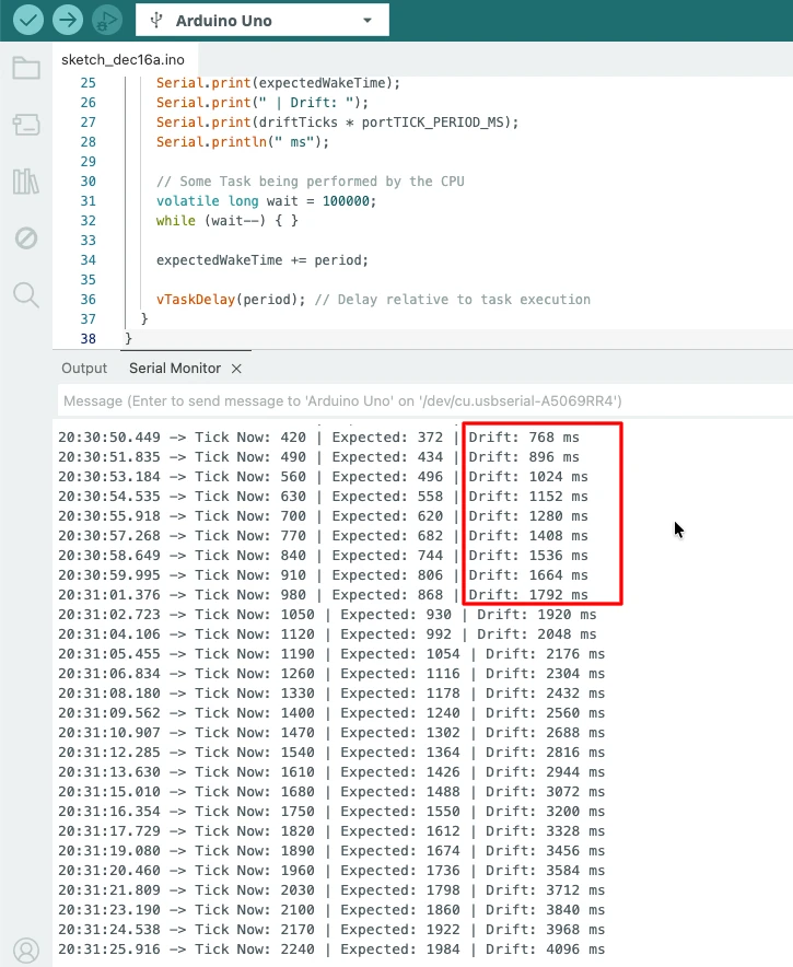
The drift grows over time, demonstrating that vTaskDelay() is relative to task completion, not an absolute schedule.
Task Using vTaskDelayUntil()
This task uses a fixed reference tick count to maintain a precise schedule. It wakes up exactly every 1000 ms, independent of task execution time, so drift does not accumulate.
Code Example
#include <Arduino_FreeRTOS.h>

void taskWithDelayUntil(void *pvParameters);

void setup() {
  Serial.begin(9600);

  xTaskCreate(taskWithDelayUntil, "DelayUntilTask", 128, NULL, 1, NULL);
}

void loop() {}

void taskWithDelayUntil(void *pvParameters) {

  const TickType_t period = pdMS_TO_TICKS(1000);
  TickType_t lastWakeTime = xTaskGetTickCount();
  TickType_t expectedWakeTime = lastWakeTime;

  while (1) {
    TickType_t nowTick = xTaskGetTickCount();
    long driftTicks = nowTick - expectedWakeTime;

    Serial.print("Tick Now: ");
    Serial.print(nowTick);
    Serial.print(" | Expected: ");
    Serial.print(expectedWakeTime);
    Serial.print(" | Drift: ");
    Serial.print(driftTicks * portTICK_PERIOD_MS);
    Serial.println(" ms");

    // Some Task being performed by the CPU
    volatile long wait = 100000;
    while (wait--) { }

    expectedWakeTime += period;

    vTaskDelayUntil(&lastWakeTime, period); // Delay aligned to fixed schedule
  }
}Explanation
vTaskDelayUntil()uses a fixed tick reference.- Any task execution time is absorbed; the next wake time is always aligned with the schedule.
- Drift remains negligible, even with CPU-intensive work.
Result
The image below shows the Serial Monitor output.
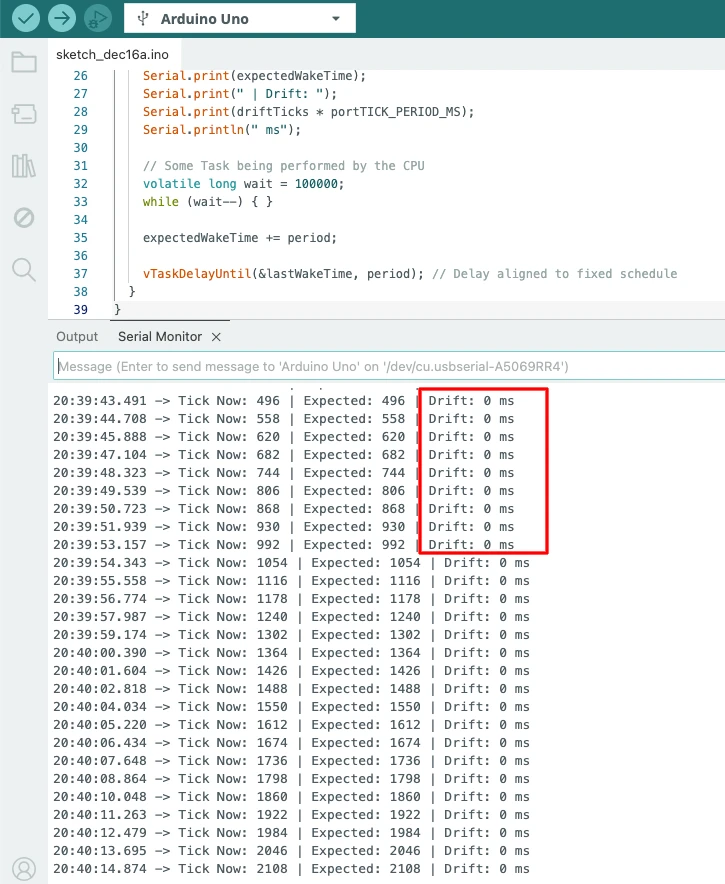
The timestamps remain evenly spaced, showing that vTaskDelayUntil() maintains a stable period, independent of task execution time.
Creating a Stable Periodic LED Task with vTaskDelayUntil()
Blinking an LED is one of the best ways to test timing accuracy. In FreeRTOS on Arduino, the correct way to create a periodic LED task is by using vTaskDelayUntil().
This method ensures the LED toggles at a fixed interval without drift.
Why This Method Is Best for Periodic Tasks
vTaskDelayUntil() uses an absolute time reference. The task wakes up at exact time intervals.
void ledTask(void *pvParameters)
{
  pinMode(2, OUTPUT);
  TickType_t lastWakeTime = xTaskGetTickCount();

  while (1)
  {
    digitalWrite(2, !digitalRead(2));
    vTaskDelayUntil(&lastWakeTime, pdMS_TO_TICKS(500));
  }
}This approach:
- Prevents timing drift
- Keeps blinking consistent
- Allows other tasks to run smoothly
It is ideal for:
- Status LEDs
- Sensor sampling
- Periodic system checks
Output
The gif below shows the LED blinking every 500 milliseconds. The blinking remains steady and accurate, even when other FreeRTOS tasks are running.

FreeRTOS Software Timers Explained (Arduino)
The FreeRTOS also provides software timers for handling time-based events. These timers run in the background using the timer service task. They are lightweight and easy to use.
Software timers are best when:
- You do not need a full task
- The action is short and non-blocking
- Timing must stay accurate
One-Shot Software Timer
A one-shot timer runs only once. It executes its callback function after the set time expires.
Typical use cases:
- Delayed actions
- Timeout handling
- Startup events
Example:
TimerHandle_t oneShotTimer;

  // -------------------------------------------------
  // Create a one-shot software timer
  // -------------------------------------------------
  oneShotTimer = xTimerCreate(
    "OneShot",             // Timer name (for debugging)
    pdMS_TO_TICKS(2000),   // Timer period in ticks (2000 ms = 2 sec)
    pdFALSE,               // pdFALSE = one-shot timer, pdTRUE = auto-reload
    NULL,                  // Timer ID (optional, can pass parameters)
    timerCallback          // Callback function to execute when timer expires
  );

  // -------------------------------------------------
  // Start the timer
  // -------------------------------------------------
xTimerStart(oneShotTimer, 0); // Second parameter = block time (0 = non-blocking)After 2 seconds, the callback runs once. The timer then stops automatically.
Auto-Reload Software Timer
An auto-reload timer runs repeatedly. It automatically restarts after every timeout. This is perfect for periodic events.
Typical use cases:
- Heartbeat LED
- Status checks
- Periodic system tasks
Example:
TimerHandle_t autoReloadTimer;

 // -------------------------------------------------
  // Create an auto-reload software timer
  // -------------------------------------------------
  autoReloadTimer = xTimerCreate(
    "AutoReload",          // Timer name (for debugging)
    pdMS_TO_TICKS(500),    // Timer period in ticks (500 ms = 0.5 sec)
    pdTRUE,                // pdTRUE = auto-reload timer, pdFALSE = one-shot
    NULL,                  // Timer ID (optional, can pass parameters)
    timerCallback          // Callback function executed on timer tick
  );

  // -------------------------------------------------
  // Start the auto-reload timer
  // -------------------------------------------------
xTimerStart(autoReloadTimer, 0); // Second parameter = block time (0 = non-blocking)The callback executes every 500 ms. Timing remains stable, even when the system load changes.
Demo: Accurate Heartbeat LED Using FreeRTOS Software Timer
A heartbeat LED is a common way to show that the system is alive. Using a FreeRTOS software timer on Arduino makes this very reliable and clean. The LED toggles at a fixed interval, independent of task execution time.
The callback function runs each time the timer expires. It should be short and non-blocking to avoid delaying the scheduler.
Timer Callback Function
// Timer callback function
// Runs every time the timer expires
// Toggles the LED
void heartbeatCallback(TimerHandle_t xTimer) {
  digitalWrite(2, !digitalRead(2));
}- The callback only toggles the LED.
- It avoids blocking operations (like delay or Serial printing).
- This ensures scheduler stability.
Create and Start the Auto-Reload Timer
// Timer handle
TimerHandle_t heartbeatTimer;

// Create the timer
heartbeatTimer = xTimerCreate(
  "Heartbeat",             // Timer name
  pdMS_TO_TICKS(500),      // Timer period (500 ms)
  pdTRUE,                  // Auto-reload timer
  NULL,                    // Timer ID (optional)
  heartbeatCallback         // Callback function
);

// Start the timer immediately
xTimerStart(heartbeatTimer, 0); // 0 = do not blockpdTRUEmakes it auto-reload, so it fires repeatedly every 500 ms.xTimerStart()starts the timer in the FreeRTOS background.
Full Working Code
#include <Arduino_FreeRTOS.h>

// Timer handle
TimerHandle_t heartbeatTimer;

// Callback function for the timer
void heartbeatCallback(TimerHandle_t xTimer) {
  digitalWrite(2, !digitalRead(2));
}

void setup() {
  // Initialize the LED
  pinMode(2, OUTPUT);

  // Create the auto-reload heartbeat timer
  heartbeatTimer = xTimerCreate(
    "Heartbeat",             // Timer name
    pdMS_TO_TICKS(500),      // Timer period (500 ms)
    pdTRUE,                  // Auto-reload
    NULL,                    // Timer ID
    heartbeatCallback         // Callback function
  );

  // Start the timer
  xTimerStart(heartbeatTimer, 0);
}

void loop() {
  // Nothing to do here, the timer runs in the FreeRTOS background
}How It Works
- The timer runs independently of the main loop.
- The built-in LED toggles every 500 ms, creating a heartbeat effect.
- Using a short, non-blocking callback ensures FreeRTOS scheduling remains smooth.
Output
The gif below shows the heartbeat LED blinking every 500 milliseconds. The timing remains consistent and stable, even when other FreeRTOS tasks are running in the background.
Complete Example: All Concepts Combined
This example demonstrates everything covered so far in a single Arduino FreeRTOS sketch:
- A periodic LED task using
vTaskDelayUntil() - Serial timestamp printing with stable timing
- A heartbeat LED driven by a FreeRTOS auto-reload software timer
This structure ensures stable timing, no blocking delays, and clean task coordination.
Full Code
#include <Arduino_FreeRTOS.h>
#include <timers.h> // Required for TimerHandle_t and software timers

/* Function Prototypes */
void ledTask(void *pvParameters);
void timingTask(void *pvParameters);
void heartbeatCallback(TimerHandle_t xTimer);

/* Software Timer Handle */
TimerHandle_t heartbeatTimer;

/* LED Pin Definitions */
const int LED1_PIN = 2; // LED controlled by periodic task
const int LED2_PIN = 3; // LED controlled by heartbeat timer

void setup() {
  Serial.begin(9600);

  // Initialize pins
  pinMode(LED1_PIN, OUTPUT);
  pinMode(LED2_PIN, OUTPUT);

  // -------------------------------
  // Create Periodic LED Task (LED1)
  // -------------------------------
  xTaskCreate(
    ledTask,
    "LED1 Task",
    128,
    NULL,
    1,
    NULL
  );

  // -------------------------------
  // Create Serial Timing Task
  // -------------------------------
  xTaskCreate(
    timingTask,
    "Timing Task",
    128,
    NULL,
    1,
    NULL
  );

  // -------------------------------
  // Create Auto-Reload Heartbeat Timer (LED2)
  // -------------------------------
  heartbeatTimer = xTimerCreate(
    "Heartbeat",
    pdMS_TO_TICKS(500),   // 500 ms period
    pdTRUE,               // Auto-reload
    NULL,
    heartbeatCallback
  );

  xTimerStart(heartbeatTimer, 0); // Start timer immediately
}

void loop() {
  // Empty. FreeRTOS scheduler handles everything
}

// -------------------------------------------------
// LED1 Task: toggles every 1 second
// -------------------------------------------------
void ledTask(void *pvParameters) {
  TickType_t lastWakeTime = xTaskGetTickCount();

  while (1) {
    digitalWrite(LED1_PIN, !digitalRead(LED1_PIN));
    vTaskDelayUntil(&lastWakeTime, pdMS_TO_TICKS(1000));
  }
}

// -------------------------------------------------
// Timing Task: prints timestamps every 1 second
// -------------------------------------------------
void timingTask(void *pvParameters) {
  TickType_t lastWakeTime = xTaskGetTickCount();

  while (1) {
    Serial.print("Timestamp (ms): ");
    Serial.println(millis());
    vTaskDelayUntil(&lastWakeTime, pdMS_TO_TICKS(1000));
  }
}

// -------------------------------------------------
// Heartbeat Timer Callback: toggles LED2 every 500 ms
// -------------------------------------------------
void heartbeatCallback(TimerHandle_t xTimer) {
  digitalWrite(LED2_PIN, !digitalRead(LED2_PIN));
}Explanation
ledTask- Toggles the LED once per second.
- Uses
vTaskDelayUntil()to maintain a stable period, independent of execution time.
timingTask- Prints timestamps every second.
- Also uses
vTaskDelayUntil()for exact timing, demonstrating stability compared tovTaskDelay().
heartbeatTimer- A FreeRTOS auto-reload software timer fires every 500 ms.
- Callback toggles another LED as a heartbeat without blocking tasks.
- Scheduler Behavior
- No
delay()is used; all tasks and timers run in the background, maintaining precise timing. - Multiple tasks and timers operate cleanly together.
- No
Output
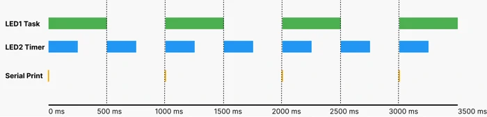
The video below shows the behavior of the two LEDs and Serial prints:
- LED1 (Pin 2) toggles every 1 second using a periodic task with
vTaskDelayUntil(). - LED2 (Pin 3) toggles every 500 ms using an auto-reload software timer.
- Serial Monitor timestamps print every 1 second, demonstrating stable timing across tasks and timers.
You can clearly observe:
- LED1 and LED2 blinking independently.
- LED2 (heartbeat) is faster, toggling twice as often.
- Serial timestamps remain evenly spaced, showing that periodic tasks maintain a precise schedule.
This combined example demonstrates best practices in Arduino FreeRTOS:
- Use
vTaskDelayUntil()for periodic tasks to prevent drift - Use software timers for short, independent periodic actions
- Avoid blocking delays in tasks or callbacks
- Ensure clean scheduling and predictable timing
Conclusion
In this post, we explored timing and scheduling in FreeRTOS on Arduino. We learned how to create periodic tasks using vTaskDelayUntil() to maintain precise timing, how vTaskDelay() can accumulate drift, and how to use auto-reload software timers for independent periodic actions, such as a heartbeat LED. We also demonstrated these concepts practically with Serial timestamp printing and two LEDs toggling at different intervals, giving a hands-on view of FreeRTOS task and timer behavior.
Understanding these timing mechanisms is extremely useful for building reliable, predictable embedded applications. Stable periodic tasks and background timers allow developers to design multitasking systems without blocking the main loop, avoid timing drift, and ensure multiple operations run concurrently without interference. This knowledge forms the foundation for more complex FreeRTOS features like event-driven programming and inter-task communication.
In the next part, Part 4 -> Queues, we will dive into task-to-task communication. You will learn how to pass data safely between tasks using FreeRTOS queues, enabling coordinated actions, messaging, and synchronization. This will build upon our timing foundation and help you design more sophisticated and responsive Arduino applications.
Browse More Arduino FreeRTOS Tutorials
FreeRTOS on Arduino (Part 2): Task Scheduling on Arduino – Tasks, Priorities & Time Slicing
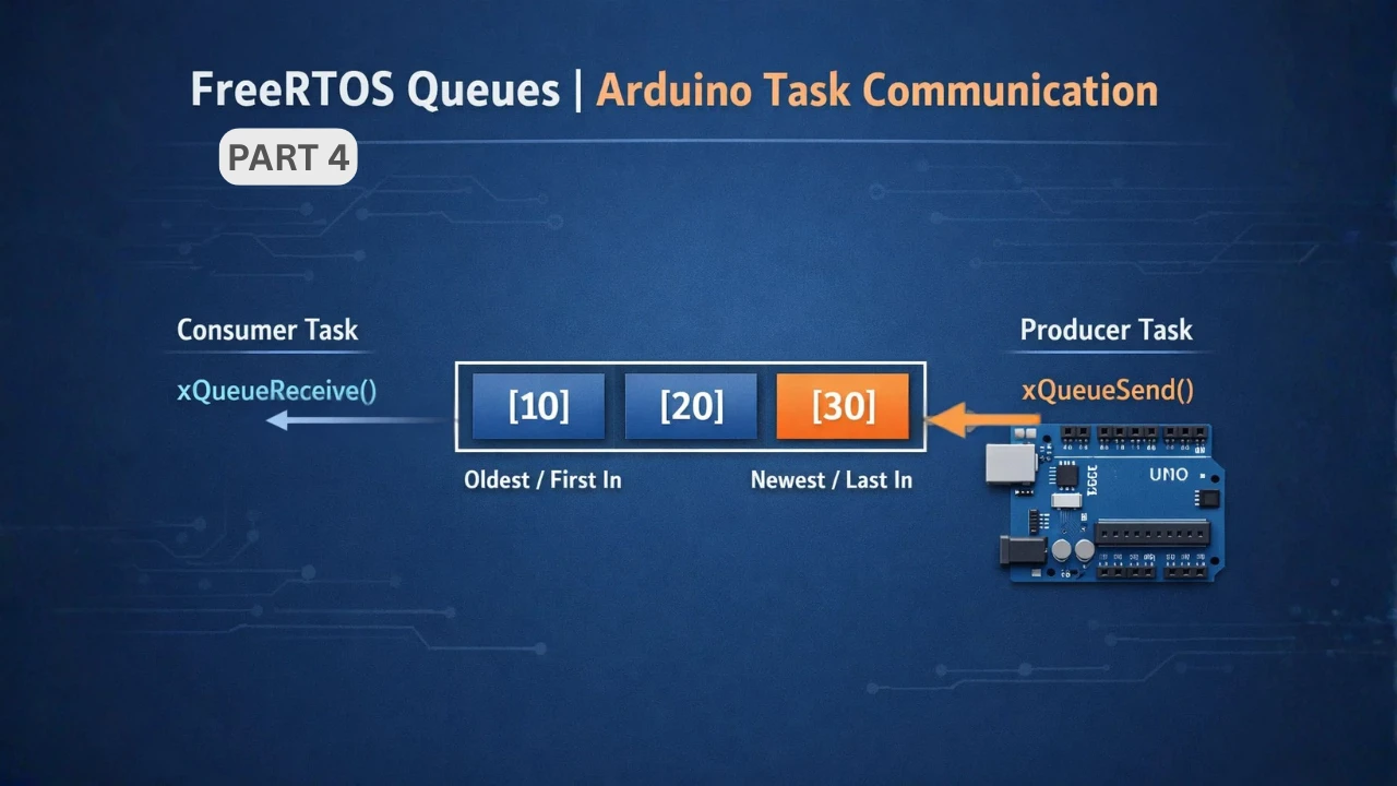
FreeRTOS on Arduino (Part 4): Inter Task Communication with Queues
FreeRTOS on Arduino (Part 5): Semaphores and Mutex Explained with Practical Examples
FreeRTOS on Arduino (Part 6): Using Interrupts in FreeRTOS

FreeRTOS Tutorial on Arduino (Part 7): Event Groups | Multi-Event Synchronization
Arduino FreeRTOS Project Download
FAQs – FreeRTOS Timing on Arduino

Subscribe
Login
0 Comments
Newest
