
Updated On: March 25, 2026
STM32 LL GPIO Input and Interrupts (EXTI): Button Press Tutorial
In this tutorial, we will learn how to use STM32 LL drivers to read a button input and trigger an EXTI interrupt. This is the continuation in the STM32 LL series and we will skip the basics like project creation, clock configuration, etc that we already covered in the previous part of this series.
You will learn three simple ways to read a button:
- Read a single input pin.
- Read the entire input port.
- Use an EXTI interrupt to detect button presses.
Introduction to STM32 LL GPIO Input and EXTI
In this part of the tutorial, we will look at how STM32 handles input pins and how LL drivers read them. We will also see why EXTI interrupts are useful when you want to react to a button press without constantly checking the pin in a loop. These concepts form the base of the code we will write later in this guide.
What Is GPIO Input in STM32?
GPIO input allows the microcontroller to read the state of a pin. The pin can be either HIGH or LOW, depending on the external signal or the button connected to it. When the pin is configured as input, the MCU does not drive it. It only senses the voltage level applied to that pin.
STM32 MCUs offer different input modes like floating, pull-up, and pull-down.
- A pull-up keeps the pin HIGH when the button is not pressed.
- A pull-down keeps the pin LOW when the button is not pressed.
This makes the reading stable and prevents random noise. With LL drivers, you can read the input state using a simple function.
Why Use LL Drivers for Input and Interrupts?
LL drivers give you fast and direct access to hardware registers. They use very little code and run quickly. This makes them ideal for applications where timing matters.
When reading input pins, LL drivers let you:
- Read a single pin quickly
- Read the entire port at once
- Toggle or control output pins with very low latency
For interrupts, LL drivers also provide clean APIs for enabling EXTI lines, clearing flags, and handling triggers. This keeps your code lightweight and predictable, which is helpful in real-time systems.
What Is EXTI (External Interrupt)?
EXTI stands for External Interrupt. It allows the MCU to react instantly when a pin changes state. Instead of checking the pin repeatedly inside the while(1) loop, the MCU can “wake up” when the button is pressed.
Each EXTI line can be mapped to specific GPIO pins. For example, EXTI1 can be connected to PA1, PB1, PC1, and so on. When the selected pin detects a rising or falling edge, it triggers an interrupt.
This event calls the interrupt handler, where you can write your response logic. Using EXTI is more efficient than polling because the CPU does not waste time checking the pin. It only acts when something actually happens, like a button press.
Configuring GPIO Input and EXTI in STM32CubeMX
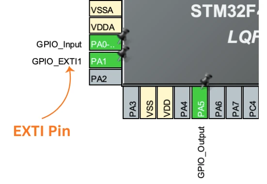
In this section, we will configure two pins. The first pin will be a simple input that we will read using LL functions. The second pin will be connected to an EXTI line, so it can trigger an interrupt when pressed. This setup lets us test all three input-reading methods used in the code.
STM32 Clock Configuration
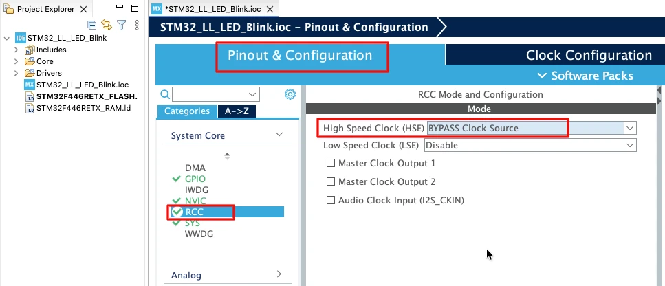
Before generating the project, we must configure the system clock. Open the Clock Configuration tab in CubeMX.
For the STM32F446RE, we will use the 8 MHz external crystal in bypass mode. This is the default clock source on the Nucleo board. The bypass mode uses the clock from the on-board ST-Link MCU.
We will feed this into the PLL and run the system at 180 MHz, which is the maximum frequency for this MCU.
The image below shows the complete PLL and clock configuration used to achieve 180 MHz.
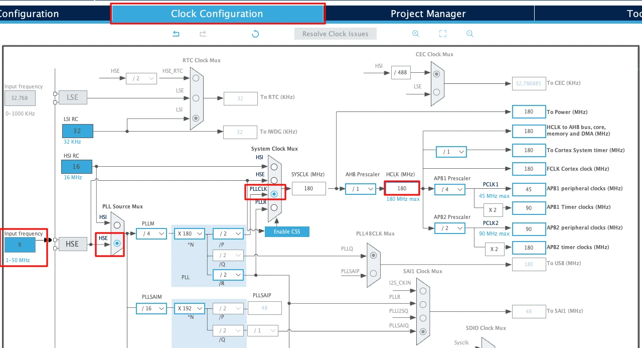
This fast system clock ensures accurate delays and smooth blinking using LL drivers. The SysTick timer will also run from this 180 MHz system clock, which becomes important in the delay functions we will use later.
Note for STM32F103C8:
This MCU uses an 8 MHz external crystal as well, but its maximum frequency is 72 MHz. If you are using the Blue Pill, configure the PLL so that the final system clock is 72 MHz.
GPIO Input Configuration
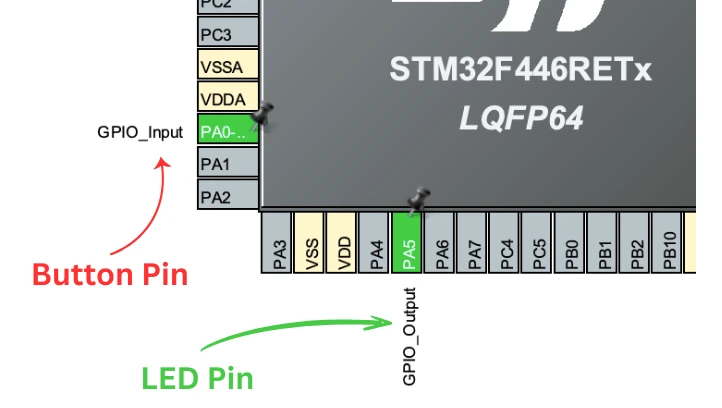
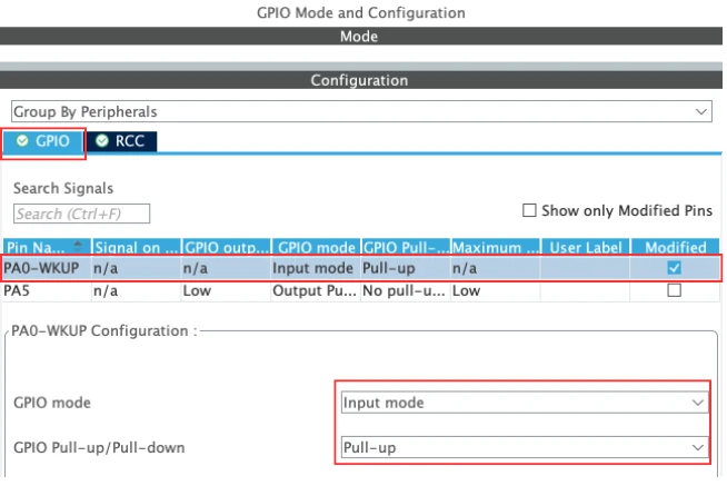
I am going to connect a button to the pin PA0. In CubeMX, configure this pin as GPIO_Input as shown in the image below.
This will be the pin we read using:
LL_GPIO_IsInputPinSet()LL_GPIO_ReadInputPort()
Next, choose a Pull-Up or Pull-Down depending on your button wiring.
- If your button connects the pin to GND when pressed, choose Pull-Up.
- If it connects the pin to 3.3V when pressed, choose Pull-Down.
This ensures the pin has a stable logic level when the button is not pressed.
I am going to connect the button to the ground, hence the pin PA0 is configured in the Pull-UP mode. The image below shows the pin configuration for PA0.
Configure PA1 as EXTI Interrupt Source
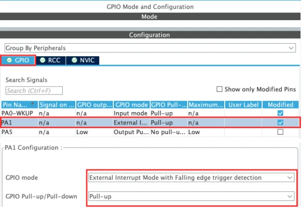
I am also going to use another button for EXTI input. This button will be connected to pin PA1. Select PA1 in cubeMX and configure it as an External Interrupt (EXTI).
CubeMX provides options like:
- Rising edge trigger -> Interrupt triggers when the button changes state from Low to High
- Falling edge trigger -> Interrupt triggers when the button changes state from High to Low
- Rising and Falling edge -> Interrupt triggers when the button changes state ( Either from Low to High or High to Low)
Choose the one that matches your button logic:
- For a button connected to GND, a Falling edge is common.
- For a button connected to 3.3V, use Rising edge.
I have connected the button to the ground, hence I am selecting the Falling Edge trigger and the pin is configured in Pull-Up mode.
NVIC Configuration for EXTI Line
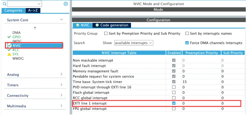
Finally, open the NVIC Settings in CubeMX.
Find the interrupt corresponding to your EXTI line:
EXTI0_IRQnfor EXTI Line 0EXTI1_IRQnfor EXTI Line 1- and so on…
Enable the IRQ and give it a priority. For simple button input, the default priority is fine.
CubeMX will generate:
NVIC_SetPriority(EXTI1_IRQn, 0);
NVIC_EnableIRQ(EXTI1_IRQn);This allows the EXTI interrupt to call its handler when the button is pressed.
STM32 LL Functions Used for GPIO Input
In this part of the tutorial, we will look at the LL functions used to read input pins and handle interrupts. These functions allow us to read a single pin, read a full port, control an LED, and respond to EXTI events. Understanding these functions will make the code in the next section easier to follow.
LL_GPIO_IsInputPinSet() -> Read a Single Pin
LL_GPIO_IsInputPinSet() is the simplest way to read an input pin. It checks if the pin is at a HIGH level (logic 1).
The function returns:
- 1 if the pin is HIGH
- 0 if the pin is LOW
Example usage:
if (LL_GPIO_IsInputPinSet(GPIOA, LL_GPIO_PIN_0) == 0)  // If the button is pressed
{
    // Do something
}
else
{
    // Do other things
}This method is easy to understand and works well when you only need to monitor one pin.
LL_GPIO_ReadInputPort() -> Read the Whole Port
LL_GPIO_ReadInputPort() reads all 16 pins of a GPIO port at once. The function returns a 16-bit value, where each bit represents the state of one pin.
This is useful when:
- You want to check multiple pins
- You want faster performance
- You need direct access to the port’s input register
Example:
uint16_t portA = LL_GPIO_ReadInputPort(GPIOA);
if ((portA & (1 << 0)) == 0)  // If PA0 == 0
{
   // Do something
}
else
{
    // Do Other things
}Reading the entire port is faster than checking each pin individually. It also gives you full control over bit operations.
EXTI Callback and Flag Handling
When the button triggers an interrupt, the EXTI hardware sets a pending flag for that line. The interrupt handler must check this flag, clear it, and then run the user code. CubeMX generates a clean template for this, and we only add our logic inside the user sections.
Inside the stm32f4xx_it.c file, cubeMX generates the EXTI handler like this:
void EXTI1_IRQHandler(void)
{
  /* USER CODE BEGIN EXTI1_IRQn 0 */

  /* USER CODE END EXTI1_IRQn 0 */
  if (LL_EXTI_IsActiveFlag_0_31(LL_EXTI_LINE_1) != RESET)
  {
    LL_EXTI_ClearFlag_0_31(LL_EXTI_LINE_1);
    /* USER CODE BEGIN LL_EXTI_LINE_1 */

    EXTI1_Triggered = 1;   // user-defined flag

    /* USER CODE END LL_EXTI_LINE_1 */
  }
  /* USER CODE BEGIN EXTI1_IRQn 1 */

  /* USER CODE END EXTI1_IRQn 1 */
}Here’s what each part does:
- LL_EXTI_IsActiveFlag_0_31() checks whether EXTI Line 1 triggered the interrupt.
This protects the handler from reacting to other EXTI lines. - LL_EXTI_ClearFlag_0_31() clears the interrupt flag.
Clearing the flag is important; otherwise, the interrupt will keep firing. - Inside the USER CODE block, we set the variable
EXTI1_Triggered = 1.
This is the only custom logic we add. We handle all LED toggling and debounce inside the main loop, not inside the interrupt.
This approach keeps the interrupt handler short and efficient. It handles only the essential work and signals the main loop to respond. This is good practice in embedded systems because long interrupt routines can block timing-critical tasks.
Hardware Connections for Buttons and LED
Before testing the input methods, we need a simple hardware setup. Two push buttons are connected to PA0 and PA1, and an LED is connected to PA5. This setup allows us to test both normal GPIO input reads and EXTI interrupts.
The image below shows the correct wiring for the buttons and the LED.
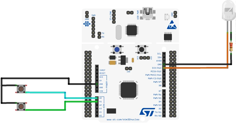
The connection is explained in the table below.
| Component | STM32 Pin | Additional Connection |
|---|---|---|
| Button 1 | PA0 | Other side to GND (use internal Pull-Up or external resistor) |
| Button 2 (EXTI) | PA1 | Other side to GND (use internal Pull-Up or external resistor) |
| LED | PA5 | LED → PA5 → Resistor → GND |
- Each button is connected between the GPIO pin and ground.
- The internal Pull-Up keeps the pin high when not pressed.
- Pressing the button pulls the pin low, which the code detects.
- The LED connected to PA5 turns ON, OFF, or toggles depending on the reading method.
- A resistor is placed in series between PA5 and GND to protect the LED.
Writing the Code for Button Press Detection
In this section, we will write the complete code used to read the button using three different techniques. These include reading a single pin, reading an entire port, and handling an EXTI interrupt. Each method has its own use case, and you will clearly see the difference in behavior.
Reading a Single Pin (LL_GPIO_IsInputPinSet)
This is the simplest and most direct method. You read only the required input pin (e.g., PA0) and act based on its state.
The code below demonstrate how to read the state of a single pin and perform some operation based on it.
int main()
{
  ....
  ....
  while (1)
  {
    /* Single Pin Reading Method */
    if (LL_GPIO_IsInputPinSet(GPIOA, LL_GPIO_PIN_0) == 0)  // If the button is pressed
    {
      LL_GPIO_SetOutputPin(GPIOA, LL_GPIO_PIN_5);  // Turn the LED ON
    }
    else
    {
      LL_GPIO_ResetOutputPin(GPIOA, LL_GPIO_PIN_5);  // Turn the LED OFF
    }
  }
}LL_GPIO_IsInputPinSet() reads the state of an input pin. It checks if the pin is at a HIGH level (logic 1).
The function returns:
- 1 if the pin is HIGH
- 0 if the pin is LOW
Since the button pin is Pulled-Up, it stays High by default. When the button is pressed, the pin PA0 is pulled to ground and the pin state will read 0.
Here we will set the pin PA5, hence turning the LED ON.
Output
The GIF below demonstrates how the LED responds when the button is pressed using the single-pin read technique.

Reading the Entire Port (LL_GPIO_ReadInputPort)
This method reads the entire input port at once, then checks the specific bit for the button pin. This is useful when reading multiple inputs efficiently.
The code below demonstrate how to read the entire port and then check for the bit 0, i.e. PA0.
int main()
{
  ....
  ....
  while (1)
  {
    /* Port Reading Method */
    uint16_t portA = LL_GPIO_ReadInputPort(GPIOA);  // Read PORTA

    if ((portA & (1 << 0)) == 0)  // If the bit 0 (PA0) = 0
    {
      LL_GPIO_SetOutputPin(GPIOA, LL_GPIO_PIN_5);  // Set the pin PA5 to High
    }
    else
    {
      LL_GPIO_ResetOutputPin(GPIOA, LL_GPIO_PIN_5);  // Reset the pin PA5 to Low
    }
  }
}After reading the Port A data, we will check the bit 0 (corresponds to pin PA0). If this bit is 0, it indicates that the button is pressed, hence we will turn the LED ON. Otherwise, the LED will turn OFF.
Output
The GIF below shows how the LED toggles based on the port-reading method.
Using EXTI Interrupt (Falling/ Rising Edge)
This method does not constantly poll in the loop. The EXTI interrupt triggers automatically when the button is pressed.
We use a flag (EXTI1_Triggered) to signal the main loop.
The code below demonstrate how to use the flag inside the while loop.
volatile int EXTI1_Triggered = 0;
int main()
{
  ....
  ....
  while (1)
  {
    /* EXTI-based Button Read */
    if (EXTI1_Triggered == 1)
    {
      LL_mDelay(200);  // debounce
      LL_GPIO_TogglePin(GPIOA, LL_GPIO_PIN_5);
      EXTI1_Triggered = 0;
    }
  }
}If the flag is set, we will toggle the LED and reset the flag. This will prevent the same loop from running again, until the flag is set in the interrupt handler again.
Interrupt Handler
The interrupt handler is generated by the CubeMX inside the stm32f4xx_it.c file. In the EXTI1_IRQHandler() function, we will simply set the flag EXTI1_Triggered. This flag is defined in the main.c file, and here it is referenced as an external variable.
extern volatile int EXTI1_Triggered;
void EXTI1_IRQHandler(void)
{
    if (LL_EXTI_IsActiveFlag_0_31(LL_EXTI_LINE_1) != RESET)
    {
        LL_EXTI_ClearFlag_0_31(LL_EXTI_LINE_1);
        EXTI1_Triggered = 1;  // flag to be added
    }
}Output
The GIF below demonstrates the EXTI-based button response, where the LED toggles only when the interrupt occurs.

Choosing the Right Input Reading Method
When to Use Simple Pin Read
Simple pin reading is perfect for projects with one or two buttons and no timing-critical requirements. It keeps everything inside the main loop and avoids unnecessary complexity.
Use this method when:
- You want the simplest implementation
- Button presses do not need precise timing
- Polling is acceptable
- CPU load is low
- You are building small projects like LED toggles, basic input demos, or prototypes
This is the easiest and most beginner-friendly technique.
When to Use Port Read
Reading the entire port is beneficial when handling multiple input pins that belong to the same GPIO port.
Use this method when:
- You need to check many inputs simultaneously
- Performance matters (only one register read)
- You are handling grouped input devices (keypads, DIP switches, button arrays)
- You want to avoid multiple LL function calls
This method is efficient and scalable for input-heavy applications.
When to Use EXTI Interrupts
EXTI interrupts are the best choice when input events must be detected instantly—even if the CPU is busy.
Use this method when:
- Button activity must trigger an action immediately
- You want to avoid polling in the main loop
- Power-saving is important (MCU can sleep until the interrupt fires)
- You’re building real-world interfaces like:
- User buttons
- Rotary encoders
- Sensors with digital alert pins
- Wake-up events
Interrupts give you the most responsive and power-efficient input handling.
Comparison Table: Simple Read vs Port Read vs EXTI Interrupt
Choosing the right input-reading method depends on your project needs. Some applications work fine with simple polling, while others require fast reactions or better scalability. The table below gives a clear, side-by-side comparison so you can decide which method fits your design.
| Feature / Method | Simple Pin Read | Port Read | EXTI Interrupt |
|---|---|---|---|
| How It Works | Reads one GPIO pin at a time | Reads all 16 pins of a port together | Triggers an interrupt when the pin changes |
| CPU Usage | Medium (polling required) | Low-Medium (single register read) | Very Low (no polling, event-driven) |
| Best For | Few buttons, simple logic | Multiple inputs on same port | Instant response, low power, real-time events |
| Scalability | Low | High | Medium (limited EXTI lines) |
| Reaction Time | Depends on loop speed | Depends on loop speed | Immediate (hardware interrupt) |
| Power Efficiency | Low | Low | Very High |
| Complexity | Easiest | Moderate | Highest |
| Typical Use Cases | Basic button read, LED control | Keypads, DIP switches, multi-button systems | User buttons, sensors with alerts, wake-up events |
Conclusion
In this tutorial, we explored how to use STM32 LL drivers to read GPIO inputs using three different methods—simple pin read, port read, and EXTI interrupts. We also learned how to configure input pins, set up EXTI in CubeMX, understand key LL functions, and write clean, debounced button-handling code. Each technique offers its own advantages, and seeing them side by side makes it easier to understand how they behave in real applications.
These methods are essential for building responsive and reliable embedded systems. Whether you are reading a single push-button, scanning multiple inputs, or reacting instantly with interrupts, this guide gives you a strong foundation to move forward. You can now pick the right approach based on your project needs and build more efficient STM32 applications with confidence.
Browse More STM32 LL Tutorials
STM32 UART using LL Drivers (Part 1): Transmit using Polling Mode
STM32 UART using LL Drivers (Part 2): Transmit using Interrupt & DMA
STM32 UART using LL Drivers (Part 3): Receive Data in Blocking Mode
STM32 UART using LL Drivers (Part 4): Receive Data in Interrupt Mode
STM32 UART using LL Drivers (Part 5): Receive Using DMA (Normal and Circular Mode)
STM32 ADC Using LL Drivers (Part 1): Single Channel Blocking and Interrupt Mode
STM32 ADC Using LL Drivers (Part 2): Multiple Channels using DMA Mode
STM32 LL Project Download
STM32 LL GPIO Input FAQs

Subscribe
Login
0 Comments
Newest
