
Updated On: February 6, 2026
Generate Precise Delays with SysCtlDelay and SysTick Timer
When working with microcontrollers, delays play a vital role in many applications. Whether it’s blinking an LED at a steady rate, waiting for a sensor to stabilize, or ensuring proper timing in communication protocols, the ability to generate accurate delays is essential.
There are multiple ways to create delays in embedded systems, ranging from simple software loops to hardware-based timers. In the case of the TM4C123G microcontroller, two common approaches are:
- SysCtlDelay function – A straightforward method provided by the TivaWare library. It’s easy to use but not highly precise since it depends on the system clock and involves software-based loops.
- SysTick timer – A hardware-based timer built into the ARM Cortex-M core. It offers much higher accuracy and flexibility, making it suitable for precise delays and periodic events.
In this tutorial, we will explore both methods, starting with the simplicity of SysCtlDelay and then moving on to the more robust and precise SysTick timer.
Recommended Resources:
I have already covered how to create a project in CCStduio and configure system clock in the previous tutorials. This tutorial is going to be a continuation in this series, so you must read the following tutorials first:
- How to Setup CCStudio and build your first project with TM4C123G
- How to configure system clock in TM4C123G
Introduction to Delay in TM4C123G
When working with the TM4C123G microcontroller, you will often come across situations where you need to pause the execution of your program for a specific period of time. This pause, or delay, is essential in embedded systems because it helps synchronize tasks, manage timing between peripherals, and create predictable behavior in your applications. Without proper delay handling, LEDs may blink too fast, sensors may not respond correctly, or communication protocols may fail.
Why do we need delay in embedded systems?
Delays are crucial in embedded applications for several reasons:
- LED Blinking and Testing: A basic “Hello World” program for microcontrollers is LED blinking. Delays help create a visible ON/OFF pattern that humans can observe.
- Sensor Stabilization: Many sensors need time to stabilize after being powered on or after a command is issued. Adding delays ensures accurate data readings.
- Communication Protocols: Interfaces like I²C, SPI, or UART may require specific timing between transactions. Delays prevent data corruption by respecting these timing requirements.
- Debouncing Switches: Mechanical switches often produce multiple unwanted signals when pressed. A short delay helps filter out this bouncing effect.
- Task Scheduling: In simple embedded applications without an RTOS, delays can act as crude timing control between different tasks.
Types of delay techniques in microcontrollers
There are multiple ways to implement delays in microcontrollers, each with its own advantages and limitations:
- Software Delays (Busy-Wait Loops)
- Implemented using simple loops that waste CPU cycles until the required time has passed.
- Easy to use but not accurate, since execution time depends on clock frequency and compiler optimization.
- Library-Based Delay Functions (e.g., SysCtlDelay in TivaWare)
- Provided by vendor libraries to simplify delay creation.
- More reliable than manual loops but still block the CPU from doing other work.
- Hardware Timer-Based Delays (e.g., SysTick Timer)
- Uses dedicated hardware timers to generate precise and consistent delays.
- Offers higher accuracy and allows the CPU to either wait or handle other tasks using interrupts.
- RTOS Delays (Task Scheduling)
- In advanced systems running a real-time operating system, delays are handled by the scheduler.
- Provides multitasking support while efficiently managing timing.
For the TM4C123G microcontroller, two of the most common methods are SysCtlDelay, a simple software-based function, and the SysTick timer, a hardware-based approach for precise timing. This tutorial will focus on these two techniques.
Setting up the Project in CCS
I have already explained how to create a new project in TM4C123 using CCStudio. You can create a similar project with blinky template and then modify it for this tutorial.
There are only 2 things we need to do to turn the blinky template into a new project:
- Delete everything from the blinky.c file, so it should be completely empty. We will write everything ourselves.
- Rename the following:
- blinky.c → main.c, indicating that this is the main file for the project
- blinky_css.cmd → linker.cmd, indicating that this is the linker file
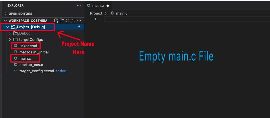
- blinky (Folder) → projectName (Folder)
The final modified project is shown in the image below.
SysCtlDelay Function in TM4C123G
The TivaWare Peripheral Driver Library provides a convenient function called SysCtlDelay that can be used to generate simple delays in TM4C123G applications. This function is widely used in beginner projects because of its simplicity. However, to use it effectively, it is important to understand how it works and where its limitations lie.
Understanding SysCtlDelay working principle
The SysCtlDelay() function works by executing a fixed number of CPU cycles in a blocking loop. Each iteration of the function consumes three clock cycles. This means the delay duration directly depends on the system clock frequency configured for the microcontroller.
The function prototype looks like this:
void SysCtlDelay(uint32_t ui32Count);- ui32Count: The number of loop iterations.
- Each loop = 3 clock cycles.
So, the total delay time can be calculated using the formula: 
For example:
- If the system clock is 16 MHz and you call
SysCtlDelay(16000000/3), the delay will be approximately 1 second. - Similarly,
SysCtlDelay(16000000/3000)will generate a delay of approximately 1 milliseond.
Limitations of SysCtlDelay
While SysCtlDelay is easy to implement, it comes with a few important limitations:
- Blocking Nature: The CPU is completely halted during the delay, meaning no other tasks can be performed in parallel.
- Clock Dependency: The delay accuracy depends heavily on the configured system clock. Any change in clock speed requires recalculating the delay value.
- Not Precise for Long Delays: Since it relies on a software loop, small variations due to compiler optimization or interrupts may affect accuracy.
- Inefficient for Real Applications: In complex systems where multitasking or power efficiency is important,
SysCtlDelayis not practical. Instead, hardware timers like SysTick should be used.
Implementing SysCtlDelay in TM4C123
The TM4C123G microcontroller provides a built-in delay function called SysCtlDelay, available through the TivaWare library. This function is often the simplest way to generate delays in your code, especially for basic tasks like LED blinking or sensor stabilization. Since it relies on software loops tied to the system clock, you can easily calculate and implement specific delay durations without needing to configure timers manually.
Example Code for Implementing SysCtlDelay
Here we will write a simple example of using SysCtlDelay to toggle the pin PF4. We will measure the toggle time on the logic analyzer to see if the delay generated is as per the calculation or not.
Include the required files
We will start with the necessary inclusions in the main.c file.
#include <stdint.h>
#include <stdbool.h>
#include "inc/hw_memmap.h"
#include "driverlib/debug.h"
#include "driverlib/gpio.h"
#include "driverlib/sysctl.h"These inclusions serves the following purposes:
<stdint.h>and<stdbool.h>→ provide standard integer types (uint32_t) andbool."inc/hw_memmap.h"→ contains base addresses for all peripherals (like GPIO ports)."driverlib/debug.h"→ enables debug/error handling support."driverlib/gpio.h"→ functions for configuring and controlling GPIO pins."driverlib/sysctl.h"→ system control functions (clock, power, enabling peripherals).
Configure system Clock
First of all we will configure the system clock, so that the delay can be calculated based on it. The function SysCtlDelay does not generate accurate delay with PLL, hence we will use the clock directly from the Main Oscillator (External 16MHz).
void systemClockConfig (void)
{
    SysCtlClockSet(SYSCTL_XTAL_16MHZ|SYSCTL_USE_OSC|SYSCTL_OSC_MAIN);
}The above function will configure the system to run at 16MHz clock, directly from the main Oscillator (External 16MHz crystal). It is already explained in another tutorial TM4C123G Clock Setup Tutorial.
Write the Delay Function
We will write a new Delay function to generate delays in milliseconds.
void delay_ms(uint32_t ms)
{
SysCtlDelay ((ms * SysCtlClockGet()) / 3000UL);
} The parameter of the function delay_ms is the milliseconds itself. Here We will call the function SysCtlDelay to generate the delay based on the system clock. The function SysCtlClockGet() outputs the current system clock.
As I already mentioned earlier that each iteration of the function SysCtlDelay() consumes three clock cycles. Therefore we need to divide the System Clock by 3 to generate 1 second Delay.
In order to generate a delay of 1 millisecond, we need to further divide the System Clock by 1000. Hence a division by 3000 is performed here.
Implement the Delay in the main function
The main function is shown below. This program blinks the LED connected to pin PF4 on the TM4C123G microcontroller using the SysCtlDelay function.
int main(void)
{
systemClockConfig();
SysCtlPeripheralEnable(SYSCTL_PERIPH_GPIOF);
while(!SysCtlPeripheralReady(SYSCTL_PERIPH_GPIOF))
{
}
GPIOPinTypeGPIOOutput(GPIO_PORTF_BASE, GPIO_PIN_4);
while(1)
{
GPIOPinWrite(GPIO_PORTF_BASE, GPIO_PIN_4, GPIO_PIN_4);
delay_ms(100);
GPIOPinWrite(GPIO_PORTF_BASE, GPIO_PIN_4, 0);
delay_ms(100);
}
}First, the code calls systemClockConfig() to set the system clock to 16 MHz. Then, it enables GPIO Port F using SysCtlPeripheralEnable() and waits until the port becomes ready.
Next, the code configures PF4 as an output pin with GPIOPinTypeGPIOOutput().
Inside the infinite loop, the program turns the LED ON, waits for 100 ms using delay_ms(100), then turns it OFF and waits again for 100 ms.
As a result, the LED on PF4 blinks continuously with a visible delay generated by the SysCtlDelay function.
Testing and Results of SysCtlDelay Delay Function
To verify the accuracy of the SysCtlDelay function, we will test the delay on the TM4C123G LaunchPad. The test uses pin PF4, which toggles every 100 ms. We will capture the output waveform using a logic analyzer. This helps confirm whether the generated delay matches the calculated timing.
The image below shows the pin timing measured by the logic analyzer.
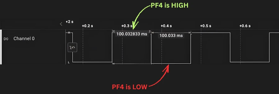
The logic analyzer capture shows the output waveform of PF4 on the TM4C123G microcontroller. The signal alternates between HIGH and LOW every 100 milliseconds, confirming that the SysCtlDelay function generates an accurate delay. The pulse width measurement displays about 100.03 ms for both HIGH and LOW periods, matching the expected 100 ms delay in the code.
The gif below shows the LED toggling with SysCtlDelay() function.

You can see the LED is blinking every 100ms. This confirms that we can use the SysCtlDelay() to provide delays.
SysTick Timer Delay in TM4C123G
The SysTick timer in the TM4C123G microcontroller is a built-in hardware timer inside the ARM Cortex-M4 core. It provides precise and stable timing, making it ideal for delay generation and time-based tasks. Unlike SysCtlDelay, which depends on CPU cycles, SysTick uses dedicated hardware and works independently of the main program flow.
Why Use SysTick Instead of SysCtlDelay
The SysCtlDelay function works well for simple projects. However, it becomes unreliable when the system uses PLL clocks or runs at higher frequencies. Because the delay is tied to the instruction cycle count, even small clock changes can cause big timing errors.
In contrast, SysTick offers consistent and accurate delays. It runs directly from the system clock or an internal reference clock, and it’s not affected by compiler optimizations or CPU instructions. Therefore, it’s the recommended method for generating precise delays in professional applications.
Advantages of Using SysTick Timer
Using SysTick delay in TM4C123G has several benefits:
- High accuracy: SysTick produces precise timing regardless of system frequency changes.
- Non-blocking operation: You can use SysTick interrupts, allowing the CPU to perform other tasks while waiting.
- Hardware-based timing: It relies on a dedicated counter, not on software loops.
- Stable with PLL: SysTick maintains consistent timing even when the PLL is used to boost the system clock.
- Scalable: Suitable for both simple delays and complex RTOS time management.
How SysTick Delay Works
The SysTick timer uses a 24-bit down counter that decreases with every clock tick. When the counter reaches zero, it can trigger an interrupt or reload automatically. By loading specific values, you can generate microsecond or millisecond delays easily.
Basically, SysTick provides stable and accurate delay generation without wasting CPU cycles — making it far superior to SysCtlDelay for most embedded applications.
Implementing SysTick Delay Using Interrupt in TM4C123G
The SysTick timer can also generate delays using interrupts. This approach is more efficient because the CPU does not remain stuck inside a delay loop. Instead, the SysTick interrupt triggers automatically after every defined time period.
This allows the microcontroller to handle other tasks while maintaining accurate timing.
Example Code for Implementing SysTick Delay
Here we will write a simple example of using the SysTick timer to toggle pin PF4 on the TM4C123G microcontroller. We will use the SysTick interrupt method for precise timing. The toggle waveform will be captured on a logic analyzer to verify that the delay matches the expected 100 ms period.
Include the Required Files
Start by including the standard headers and the driverlib files.
#include <stdint.h>
#include <stdbool.h>
#include "inc/hw_memmap.h"
#include "driverlib/sysctl.h"
#include "driverlib/systick.h"
#include "driverlib/gpio.h"
#include "driverlib/interrupt.h" // for IntMasterEnableThese libraries give access to SysTick functions, GPIO control, and system configuration for the Tiva C TM4C123G. Also include the driverlib/interrupt.h to implement the interrupt functionality.
Configure system Clock
First, we configure the system clock to ensure accurate delay calculation. We use the main oscillator (external 16 MHz)and enable the PLL to boost the system clock to the maximum 80 MHz. This provides a stable and high-speed clock for the SysTick timer.
void systemClockConfig (void)
{
    SysCtlClockSet(SYSCTL_XTAL_16MHZ|SYSCTL_USE_OSC|SYSCTL_OSC_MAIN);
}
The above function will configure the system to run at 80MHz clock. It is already explained in another tutorial TM4C123G Clock Setup Tutorial.
Global Variables
We’ll use a simple counter variable to track time.
volatile uint32_t msTicks = 0;The volatile keyword prevents the compiler from optimizing it away since the variable updates inside an interrupt routine.
SysTick Interrupt Handler
This function executes automatically whenever the SysTick timer generates an interrupt.
void SysTick_Handler(void)
{
    msTicks++;   // increment every millisecond
}Each interrupt increments the msTicks by one, creating a 1 ms software timer.
SysTick Initialization Function
Now let’s initialize SysTick to generate an interrupt every 1 millisecond.
void SysTick_Init(void)
{
    SysTickPeriodSet(SysCtlClockGet() / 1000); // 1ms period
    SysTickIntRegister(SysTick_Handler);     // Register ISR
    SysTickIntEnable();                        // Enable SysTick interrupt
    SysTickEnable();                           // Start SysTick
}The function SysTick_Init() will initialize the SysTick counter. Here’s what happens:
SysTickPeriodSet()sets the reload value.SysTickIntRegister()links the interrupt handler function.SysTickIntEnable()activates the SysTick interrupt.- Finally,
SysTickEnable()starts the timer.
Delay Function Using SysTick
Now, we will write a function that waits for a specified number of milliseconds.
void delay_ms(uint32_t ms)
{
    uint32_t start = msTicks;
    while ((msTicks - start) < ms) {}
}his function records the starting tick count and waits until the required number of milliseconds has passed. It’s non-blocking, meaning the CPU can still handle interrupts while waiting.
Implement the Delay in the main function
We will now test the SysTick delay by blinking an LED on PF4.
int main(void)
{
    systemClockConfig();

    // Enable the GPIOF Clock and configure PG4 as output
    SysCtlPeripheralEnable(SYSCTL_PERIPH_GPIOF);
    while(!SysCtlPeripheralReady(SYSCTL_PERIPH_GPIOF))
    {
    }
    GPIOPinTypeGPIOOutput(GPIO_PORTF_BASE, GPIO_PIN_4);

    IntMasterEnable();
    SysTick_Init();

    while(1)
    {
        GPIOPinWrite(GPIO_PORTF_BASE, GPIO_PIN_4, GPIO_PIN_4);  // Set the PF4 High
        delay_ms(100);
        GPIOPinWrite(GPIO_PORTF_BASE, GPIO_PIN_4, 0);  // ReSet the PF4 Low
        delay_ms(100);
    }
}First, the code calls systemClockConfig() to set the system clock to 80 MHz. Then, it enables GPIO Port F using SysCtlPeripheralEnable() and waits until the port becomes ready.
Next, the code configures PF4 as an output pin with GPIOPinTypeGPIOOutput().
Next, IntMasterEnable() enables global interrupts, allowing the SysTick interrupt to run. Then, SysTick_Init()starts the SysTick timer with 1 ms tick and links the interrupt handler.
Inside the infinite loop, the code sets PF4 high using GPIOPinWrite(), waits 100 ms using the SysTick-based delay, then sets PF4 low and waits another 100 ms.
As a result, the LED on PF4 blinks continuously with accurate timing generated by the SysTick interrupt.
Testing and Results of SysCtlDelay Delay Function
To verify the accuracy of the SysTick Timer, we will test the delay on the TM4C123G LaunchPad. The test uses pin PF4, which toggles every 100 ms. We will capture the output waveform using a logic analyzer. This helps confirm whether the generated delay matches the calculated timing.
The image below shows the pin timing measured by the logic analyzer.
The logic analyzer capture shows the output waveform of PF4 on the TM4C123G microcontroller. The signal alternates between HIGH and LOW every 100 milliseconds, confirming that the SysTick Timer generates an accurate delay. The pulse width measurement displays about 100.03 ms for both HIGH and LOW periods, matching the expected 100 ms delay in the code.
The gif below shows the LED toggling with SysTick Timer.
You can see the LED is blinking every 100ms. This confirms that we can use the SysTick Timer to provide accurate delays at higher PLL clock.
Advantages of Using SysTick Delay
Using SysTick in the TM4C123G microcontroller provides stable and predictable timing, even at higher system clock speeds. This is especially important when using the PLL clock, which increases the system frequency to 80 MHz. Unlike SysCtlDelay, which depends on CPU instruction cycles and can become inaccurate at higher speeds, SysTick delivers precise delays based on a hardware counter.
Moreover, SysTick with interrupts allows the CPU to remain free for other tasks while the delay runs in the background. This non-blocking behaviour makes it ideal for real-time applications and multitasking.
Other benefits include:
- High accuracy: Each tick is synchronized with the system clock.
- Hardware-based timing: The timer operates independently of software loops.
- Scalability: It can generate microsecond or millisecond delays as needed.
- Interrupt-driven: Perfect for RTOS tasks or periodic events without halting the main program.
SysTick provides a precise, efficient, and reliable method for delay generation on the Tiva C TM4C123G, making it the preferred choice for professional embedded applications.
Why SysCtlDelay is Not Reliable at Higher Speeds
The SysCtlDelay function works by executing a fixed number of CPU instructions in a loop. Its timing depends directly on the system clock frequency and the number of instructions executed per loop.
When the PLL clock is used to increase the system frequency (for example, from 16 MHz to 80 MHz), the CPU executes instructions faster. As a result, the delay generated by SysCtlDelay becomes shorter than expected.
Additionally, compiler optimizations or other background tasks can further affect the timing, making SysCtlDelay unreliable for precise applications.
Why SysTick Solves This Problem
In contrast, the SysTick timer uses a dedicated hardware counter that counts clock ticks independently of the CPU instructions.
- It remains accurate even when the system clock changes or PLL is enabled.
- It can generate millisecond or microsecond delays reliably.
- When combined with interrupts, it does not block the CPU, allowing other tasks to run concurrently.
Thus, for applications requiring stable and precise timing, especially at higher clock speeds, SysTick is the preferred choice over SysCtlDelay.
Conclusion
In this tutorial, we explored delay generation on the TM4C123G microcontroller using both SysCtlDelay and SysTick timer methods. We saw that SysCtlDelay works for simple delays but becomes unreliable at higher system speeds or when using the PLL clock.
On the other hand, SysTick, especially with the interrupt method, provides precise, stable, and non-blocking delays. It allows the CPU to perform other tasks while maintaining accurate timing, making it ideal for real-time applications and multitasking systems.
By testing the delays on a logic analyzer, we confirmed that SysTick delivers accurate timing, proving it is the preferred method for professional embedded applications using the Tiva C TM4C123G LaunchPad.
Browse More TM4C123G Tutorials
TM4C123 Clock Configuration: Main Oscillator, PIOSC & PLL with TivaWare

TM4C123 GPIO Tutorial – Digital Input and Output using Tiva C LaunchPad

TM4C123 GPIO External Interrupts (Using TivaWare in Code Composer Studio)

TM4C123G UART Tutorial (PART 1) – How to Use UART and Virtual COM Port in Tiva C

TM4C123G UART Tutorial (PART 2): Use Interrupt to Receive Data and Control LEDs

I2C in TM4C123G Tiva C – How to Use I2C Peripheral with TivaWare
TM4C123G SPI Tutorial: Configure SSI0 & Read ADXL345 with TivaWare
TM4C123G Delay Project Download
TM4C123G Delay FAQs

Subscribe
Login
0 Comments
Newest
