
Home ▸ STM32 Tutorials ▸ STM32 IoT ▸
Updated On: February 6, 2026
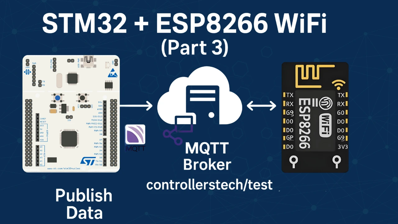
How to Connect to MQTT broker and publish Messages
In this tutorial, you will learn how to connect an STM32 microcontroller with an ESP8266 WiFi module to an MQTT broker and publish messages to a topic. MQTT is a lightweight messaging protocol designed for IoT projects, and it allows devices to communicate reliably with cloud servers or other clients.
We will go step by step, starting from hardware connections, creating the MQTT connect packet, and then publishing data to the broker. You will also see how to test the setup using MQTT Explorer and confirm that your STM32 client is sending messages successfully.
By the end of this guide, you will understand how to use STM32 and ESP8266 together for MQTT communication and build a solid base for more advanced IoT projects like sending sensor data, subscribing to topics, or using RTOS for message handling.
Introduction to MQTT with STM32 and ESP8266
MQTT is one of the most popular communication protocols used in IoT projects today. When paired with an STM32 microcontroller and an ESP8266 WiFi module, it provides a reliable and lightweight way to send and receive data between devices and the cloud. This combination is widely used in embedded systems where low power, efficiency, and stability are important.
What is MQTT and Why Use It in IoT Projects
MQTT (Message Queuing Telemetry Transport) is a lightweight publish-subscribe protocol designed for devices that have limited resources and unreliable networks. Instead of sending data directly to each device, MQTT uses a broker to manage all communication. Clients can publish messages to specific topics, and other clients subscribed to those topics will automatically receive the data.
This model makes MQTT very efficient, especially in IoT applications such as smart homes, industrial monitoring, or sensor networks. It reduces bandwidth usage, ensures reliable message delivery, and makes it easier to scale projects with many devices.
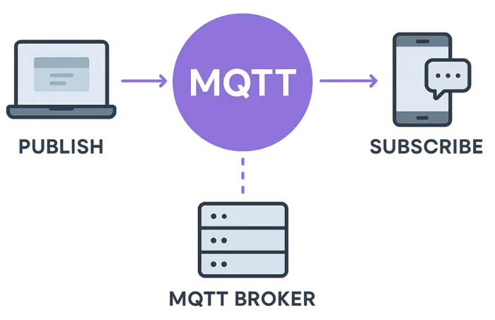
MQTT uses a publish/subscribe system with three main parts:
- Publisher – The device or program that sends data.
Example: A temperature sensor publishing the current room temperature. - Subscriber – The device or program that wants to receive data.
Example: A mobile app that shows the temperature reading. - Broker – The middleman (server) that connects publishers and subscribers.
Example: An MQTT broker like Mosquitto, HiveMQ, or EMQX.
Step-by-Step Flow:
- Connecting to the Broker
- Both publishers and subscribers connect to the MQTT broker using a lightweight network connection (often over TCP/IP).
- Publishing a Message
- The publisher sends a message to a specific topic (like a label or category).
- Example topic:
home/livingroom/temperature.
- Delivering to Subscribers
- The broker receives the message and sends it to all subscribers who have subscribed to that topic.
- Using QoS Levels
- Depending on the Quality of Service (QoS) level, the broker ensures the message is delivered at least once, exactly once, or just once without confirmation.
- No Direct Connections Between Devices
- Publishers and subscribers never talk directly — they only talk to the broker.
- This makes the system scalable and easier to manage.
Overview of STM32 and ESP8266 for MQTT Communication
The STM32 is a powerful ARM-based microcontroller, known for its performance, low power consumption, and flexibility. It is widely used in embedded and IoT applications where reliability and speed are essential. However, STM32 boards do not have built-in WiFi connectivity, which is where the ESP8266 comes in.
The ESP8266 is a low-cost WiFi transceiver module that allows microcontrollers to connect to the internet easily. When used with STM32, the ESP8266 handles all WiFi-related tasks, while the STM32 focuses on application logic, sensor data processing, and running MQTT client functions.
By combining STM32 with ESP8266, you can create an IoT device that connects to an MQTT broker, publishes messages to topics, and even subscribes to receive data, making it ideal for cloud-based communication.
STM32 MQTT Project Requirements
Before we begin building our STM32 ESP8266 MQTT project, let’s take a quick look at the tools and components you’ll need. This includes both hardware and software required for the project.
- Hardware:
- Software:
- STM32CubeIDE
- MQTT Broker (I am going to use the HiveMQ Public broker for testing)
- MQTT Client (Optional us it for testing)
- Internet access
Prerequisites:
You must take a look at the following tutorials before continuing with this one,
- STM32 IoT with ESP8266 (Part 1): Connect STM32 to WiFi and Obtain IP Address
- STM32 IoT with ESP8266 (Part 2): – Send Sensor Data to ThingSpeakCloud
Connecting STM32 and ESP8266 for MQTT
To connect the ESP8266 WiFi module with STM32, we use the UART pins for communicating with the module. Along with the basic connections (power, TX, RX, and GND), adding a USB to TTL converter is very handy for debugging and logging, so you can easily see what’s happening during the STM32 WiFi setup.
Hardware Connections and Pin Configuration
I’m using an ESP-01 Adapter with the ESP8266-01 module. This adapter makes things easier by reducing the connections from 8 pins to just 4. The image below shows how the module is connected using the adapter.
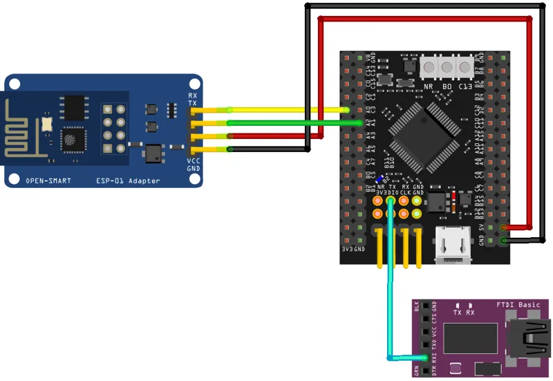
Always make UART connections in a cross pattern: connect TX to RX and RX to TX.
- Connect the TX pin from the Adapter to PA0 (UART4_RX) and the RX pin to PA1 (UART4_TX).
- Power the Adapter with 5V from the MCU. The ST-Link provides only 3.3V, so connect the USB cable to the dev board to supply 5V.
The Adapter’s onboard voltage regulator converts 5V to 3.3V for the ESP8266-01 module. If you use an external power supply for the module, ensure the supply and STM32 dev board share a common ground.
FTDI (FT232) Module
We use it to view user interaction logs on the serial console. Since we only send data from STM32 to the FTDI, connect PA10 (UART1_TX) to the RX pin of the module.
Configuring the ESP8266 for MQTT Communication
We will start configuring the UART4 to connect the ESP8266-01 module.
UART4 (ESP8266) Configuration
The image below shows the UART4 configuration.
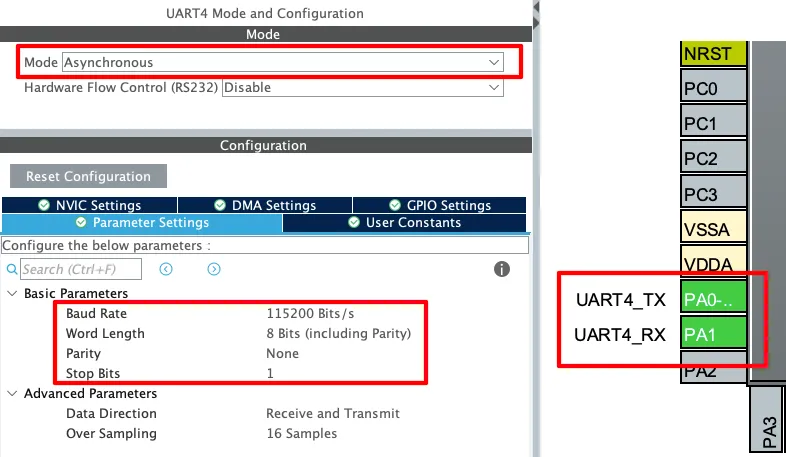
The UART must be configured in the Asynchronous mode. Leave the Parameter configuration to default, with 8 bits Word Length, no Parity and 1 Stop bit. The pins PA0 and PA1 are configured as the UART TX and RX pins.
The Baud Rate configuration here should match the Baud Rate of the ESP8266 Module. The default baud rate of ESP8266-01 is 115200, but you should still test it prior connecting to the MCU.
You check the video to see how to test the module to find the correct baud rate.
UART1 (FT232) Configuration
As I mentioned earlier, the user interactive logs will be sent through UART1 to the FT232, which will then be displayed on the serial console. The image below shows the UART1 configuration.
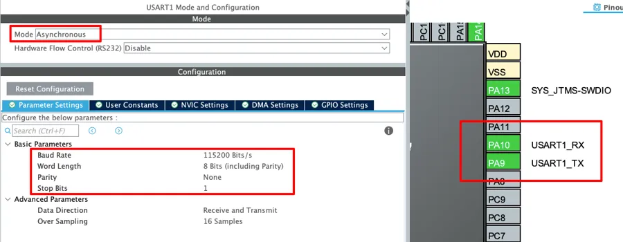
The UART1 is configured in the Asynchronous mode. The Baud rate is set to 115200 Bits/s with 8 Bits of word length, No parity and 1 Stop bit. We can configure this however we want, but this is an optimal configuration.
The pins PA9 and PA10 are configured as the UART1_TX and UART1_RX pins respectively. Since we only need to transmit data to the FTDI, PA9 (UART1_TX) is connected to FTDI RX as mentioned in the wiring diagram.
Understanding MQTT Packets and Commands
MQTT communication is based on small control packets exchanged between the client and the broker. Each packet follows a defined structure, and understanding this format helps in building reliable IoT applications with STM32 and ESP8266. Two of the packets that we will cover today are the Connect packet and the Publish packet.
MQTT Connect Packet Structure Explained
The Connect packet is the very first message a client sends to the MQTT broker. It lets the broker know that a new device wants to establish a session. The Connect packet is divided into three parts:
- Fixed Header – This section defines the packet type (for connect it is
0x10) and the remaining length of the packet. - Variable Header – This includes important details such as the protocol name (
MQTT), protocol level, connect flags (like clean session, username, password), and the keep-alive interval. - Payload – This carries client-specific data such as the Client ID, username, password, and optional fields like will topic and will message.
The image below shows an example of the connect packet containing username and password.
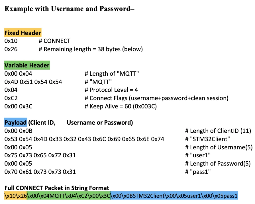
This image illustrates the composition of an MQTT CONNECT packet when authentication using a Client ID, Username, and Password is required. The packet is divided into three logical parts: the fixed header, the variable header, and the payload.
- The fixed header defines the type of packet being transmitted, which in this case is a CONNECT request. It also specifies the total length of the remaining packet. This ensures that the broker knows how many bytes must be processed for the connection request.
- The variable header provides session-related details. It identifies the protocol as MQTT with version 3.1.1 (Protocol Level = 4), sets connection flags to indicate the use of username, password, and a clean session, and defines a keep-alive interval of 60 seconds. These fields guide the broker in establishing and maintaining the client’s session.
- The payload carries the authentication and identification details of the client. In this example, the payload contains the Client ID “STM32Client,” along with a username and password. Each of these fields is length-prefixed, meaning that the broker first reads the specified length before interpreting the actual data. This method allows the broker to parse variable-length fields reliably.
At the bottom, the complete packet is represented in its raw byte-stream form. This shows the exact sequence of bytes transmitted by the STM32 through the ESP8266 to the MQTT broker.
The broker reads this packet and, if everything is correct, responds with a Connect Acknowledgement (CONNACK). This confirms that the STM32 + ESP8266 client is now successfully connected to the MQTT broker.
MQTT Publish Packet and Payload Format
Once connected, the client can send messages to a topic using the Publish packet. This packet also has three main parts:
- Fixed Header – It starts with the packet type (
0x30for publish) and includes flags such as QoS, duplicate, and retain. For simple IoT projects, QoS is usually set to 0 to keep things lightweight. - Variable Header – This contains the topic name where the message will be published. The length of the topic name is included, followed by the topic string itself.
- Payload – This is the actual message that the STM32 wants to publish. Unlike the topic, the payload does not include a length field and simply carries the data directly.
For example, if the STM32 publishes the message “Hello STM32” to the topic controllerstech/test, the Publish packet will first define the header and topic, and then append the string message as the payload. This is shown in the image below.
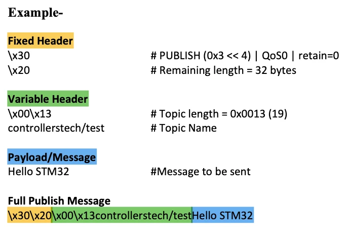
This image demonstrates the structure of an MQTT PUBLISH packet, which is used to send a message to a specific topic on the broker. The packet consists of three key sections: the fixed header, the variable header, and the payload.
- The fixed header identifies the packet as a PUBLISH command. It also encodes the Quality of Service (QoS) level, the retain flag, and specifies the remaining length of the packet. In this example, QoS is set to 0 and the retain flag is disabled, while the broker is informed that 32 bytes of data follow.
- The variable header defines the topic to which the message will be published. Here, the topic is
controllerstech/test, and its length is explicitly provided so that the broker can correctly interpret the topic string. This ensures that the message is routed to the correct subscribers. - The payload contains the actual data being transmitted. In this case, the message is the string “Hello STM32.” The payload can carry any data format, but in MQTT it is simply treated as a sequence of bytes.
At the bottom, the complete packet is shown in raw byte format. This illustrates how the different components — header information, topic definition, and payload — are combined into a single stream of data for transmission.
Since we are using QoS 0, the broker does not send an acknowledgement for Publish packets. The ESP8266 module, however, confirms that the packet was sent successfully, so we can still verify that the data has been transmitted.
Writing the MQTT Connect Function
Establishing a stable connection between the STM32 and the MQTT broker is the first step before publishing or subscribing to messages. This process is handled by the ESP_MQTT_Connect function, which builds the MQTT CONNECT packet, sends it through the ESP8266 module, and waits for the broker’s acknowledgment. Let’s break this process into smaller parts.
Parameters Required for MQTT Connection
The ESP_MQTT_Connect function is as follows:
ESP8266_Status ESP_MQTT_Connect(const char *broker, uint16_t port, const char *clientID,
const char *username, const char *password, uint16_t keepalive)To initiate the connection, the function requires several parameters:
- Broker Address and Port: The IP address or domain name of the MQTT broker along with the port number.
- Client ID: A unique identifier for the STM32 client. This helps the broker distinguish between different devices.
- Username and Password: Optional fields, used only if the broker requires authentication.
- Keep Alive Interval: A timer value (in seconds) that tells the broker how often the client will communicate to stay connected.
These parameters are passed into the ESP_MQTT_Connect function, ensuring the STM32 can connect to different brokers and configurations flexibly.
Sending the Connect Packet to the Broker
The function executes the connection process in multiple steps:
- TCP Connection Setup:
The ESP8266 is instructed to open a TCP connection to the broker using the AT commandAT+CIPSTART. If this step fails, the broker is unreachable.
    /****** Step 1: TCP connect ******/

    snprintf(cmd, sizeof(cmd), "AT+CIPSTART=\"TCP\",\"%s\",%d\r\n", broker, port);
    res = ESP_SendCommand(cmd, "CONNECT", 5000);
    if (res != ESP8266_OK){
    	 DEBUG_LOG("CIPSTART Failed with ESP ERROR %d..", res);
    	 return res;
}- Building the MQTT CONNECT Packet:
The helper functionMQTT_BuildConnectconstructs the CONNECT packet in compliance with the MQTT protocol.- It creates the fixed header with packet type information.
- It adds the variable header, including the protocol name (
MQTT), protocol level, connection flags, and keep-alive timer. - Finally, it appends the payload, which carries the client ID, and optionally the username and password.
/****** Step 2: Build MQTT CONNECT packet ******/
len = MQTT_BuildConnect(packet, clientID, username, password, keepalive);

static int MQTT_BuildConnect(uint8_t *packet, const char *clientID, const char *username, const char *password, uint16_t keepalive)
{
    int len = 0;
    /* Fixed Header */
    packet[len++] = 0x10;   // CONNECT packet type
    int remLenPos = len++;  // Remaining length placeholder

    /* Variable Header */
    packet[len++] = 0x00; packet[len++] = 0x04;
    packet[len++] = 'M'; packet[len++] = 'Q'; packet[len++] = 'T'; packet[len++] = 'T';
    packet[len++] = 0x04;   // Protocol Level = 4 (MQTT 3.1.1)

    uint8_t connectFlags = 0x02; // Clean Session
    if (username) connectFlags |= 0x80;
    if (password) connectFlags |= 0x40;
    packet[len++] = connectFlags;

    // Keep Alive
    packet[len++] = (keepalive >> 8) & 0xFF;
    packet[len++] = (keepalive & 0xFF);

    /* Payload */
    // Client ID
    uint16_t cid_len = strlen(clientID);
    packet[len++] = cid_len >> 8;
    packet[len++] = cid_len & 0xFF;
    memcpy(&packet[len], clientID, cid_len); len += cid_len;

    // Username
    if (username) {
        uint16_t ulen = strlen(username);
        packet[len++] = ulen >> 8;
        packet[len++] = ulen & 0xFF;
        memcpy(&packet[len], username, ulen); len += ulen;
    }

    // Password
    if (password) {
        uint16_t plen = strlen(password);
        packet[len++] = plen >> 8;
        packet[len++] = plen & 0xFF;
        memcpy(&packet[len], password, plen); len += plen;
    }

    // Remaining length from Fixed Header
    packet[remLenPos] = len - 2;  // remove first 2 bytes of Fixed Header
    return len;
}- Sending Data Length:
Before sending the actual packet, the ESP8266 is told how many bytes will be transmitted using theAT+CIPSENDcommand.
/****** Step 3: Tell ESP how many bytes to send ******/

    snprintf(cmd, sizeof(cmd), "AT+CIPSEND=%d\r\n", len);
    res = ESP_SendCommand(cmd, ">", 2000);
    if (res != ESP8266_OK){
    	DEBUG_LOG("CIPSEND Failed with ESP ERROR %d..", res);
    	 return res;
}- Sending the CONNECT Packet:
The complete binary CONNECT packet is then sent to the broker.
    /****** Step 4: Send packet and wait for CONNACK ******/

    res = ESP_SendBinary(packet, len, "\x20", 5000);
    if (res != ESP8266_OK){
    	DEBUG_LOG("Send Connect Command Failed with ESP ERROR %d..", res);
    	USER_LOG("MQTT CONNACK failed.");
    	 return res;
}Handling the Broker’s Connection Acknowledgment
Once the CONNECT packet is sent, the client expects a CONNACK (Connection Acknowledgment) from the broker.
- If the broker accepts the connection, it responds with a valid CONNACK packet.
- The function logs a success message, confirming that the STM32 is now an MQTT client connected to the broker.
- If the CONNACK is not received or indicates an error, the function logs a failure and exits.
	USER_LOG("MQTT CONNACK received, broker accepted connection.");
return ESP8266_OK;Implementing the MQTT Publish Function
The ESP_MQTT_Publish() function is responsible for publishing data to a given MQTT topic with a specified QoS level. It builds the MQTT publish packet, instructs the ESP8266 to send it, and waits for confirmation from the broker.
Building the Publish Packet
The packet is created in three parts:
- Fixed Header
- The first byte identifies the control packet type as PUBLISH (0x30).The QoS value is also encoded into this byte.The second byte (Remaining Length) is calculated later and updated once the full packet size is known.
/* Fixed Header */
packet[len++] = 0x30 | (qos << 1); // PUBLISH, QoS
int remLenPos = len++; // will be calculated later- Variable Header
- Contains the Topic Name (2-byte length field + topic string).If QoS > 0, a Packet Identifier would also be included (not implemented in this snippet).
/* Variable Header */
// Topic
uint16_t tlen = strlen(topic);
packet[len++] = tlen >> 8;  // store topic len
packet[len++] = tlen & 0xFF;  // store topic len
memcpy(&packet[len], topic, tlen); len += tlen; // store topic- Payload
- The actual message data to be delivered to the subscribers of the topic.
/* Payload */
// Message
uint16_t mlen = strlen(message);
memcpy(&packet[len], message, mlen); len += mlen; // store message- Remaining Length
- After packet construction, the remaining length is written back into the header.
// Remaining length
packet[remLenPos] = len - 2; // remove first 2 bytes of Fixed HeaderSending Messages to a Specific Topic
Once the packet is built, the ESP8266 must be instructed to send it to the broker:
- Tell ESP how many bytes to send
- The
AT+CIPSENDcommand specifies the length of the upcoming packet.
- The
/****** Step 2: Tell ESP how many bytes to send  ******/
snprintf(cmd, sizeof(cmd), "AT+CIPSEND=%d\r\n", len);
res = ESP_SendCommand(cmd, ">", 2000);
if (res != ESP8266_OK){
	DEBUG_LOG("CIPSEND Failed with ESP ERROR %d..", res);
	return res;
}- Send the actual binary packet
- The packet is then transmitted, and the function waits for
"SEND OK"from the ESP8266.
- The packet is then transmitted, and the function waits for
/****** Step 3: Send packet and wait for ACK ******/

res = ESP_SendBinary(packet, len, "SEND OK", 5000);
if (res != ESP8266_OK){
	DEBUG_LOG("Publish Command Failed with ESP ERROR %d..", res);
  return res;
}If both steps succeed, the message has been successfully published.
Practical Example with STM32 Client
Let’s walk through a simple example where an STM32 device connects to a public MQTT broker and continuously publishes data. This demonstrates how the publish function can be used in a real-world loop.
In this example, after the STM32 connects to the Wifi Network, it connects to the free HiveMQ broker, then enters an infinite loop where it sends incremental messages to a test topic.
int main()
{
  ....
  ....
  if (ESP_Init() != ESP8266_OK){
	  USER_LOG("Failed to initialize... Check Debug logs");
	  Error_Handler();
  }

  if (ESP_ConnectWiFi("Arun_Rawat", "arun@321", ip_buf, sizeof(ip_buf)) != ESP8266_OK){
	  USER_LOG("Failed to connect to wifi... Check Debug logs");
	  Error_Handler();
  }

  if (ESP_MQTT_Connect("broker.hivemq.com", 1883, "STM32Client", NULL, NULL, 60) != ESP8266_OK){
	  Error_Handler();
  }

  while (1)
  {
	  sprintf (count_arr, "STM32: %d", count1++);

	  if (ESP_CheckTCPConnection() == ESP8266_OK){
		  ESP_MQTT_Publish("controllerstech/test1", count_arr, 0);
	  }
  }
}Publishing Continuous Messages in a Loop
After establishing a successful connection with the MQTT broker, the code enters the main loop.
- A counter variable (
count1) is incremented each time the loop runs. - The counter value is formatted into a string using
sprintf(). - Before publishing, the client checks whether the TCP connection is still active.
- If the connection is alive, it publishes the message to the specified topic.
This ensures that the STM32 keeps publishing fresh data continuously, as long as the broker connection remains valid.
Example sequence of published messages to the topic controllerstech/test1.
"STM32: 0""STM32: 1""STM32: 2"- … and so on.
Any client subscribed to this topic will receive the stream of counter updates from the STM32 board.
Result: MQTT Publish in Action
After running the code, the STM32 client successfully connects to the HiveMQ broker and starts publishing messages to the topic controllerstech/test1. On the subscriber side, MQTT Explorer is used to monitor the topic in real time.
As the loop executes, MQTT Explorer displays an incremental stream of messages as shown in the image below.
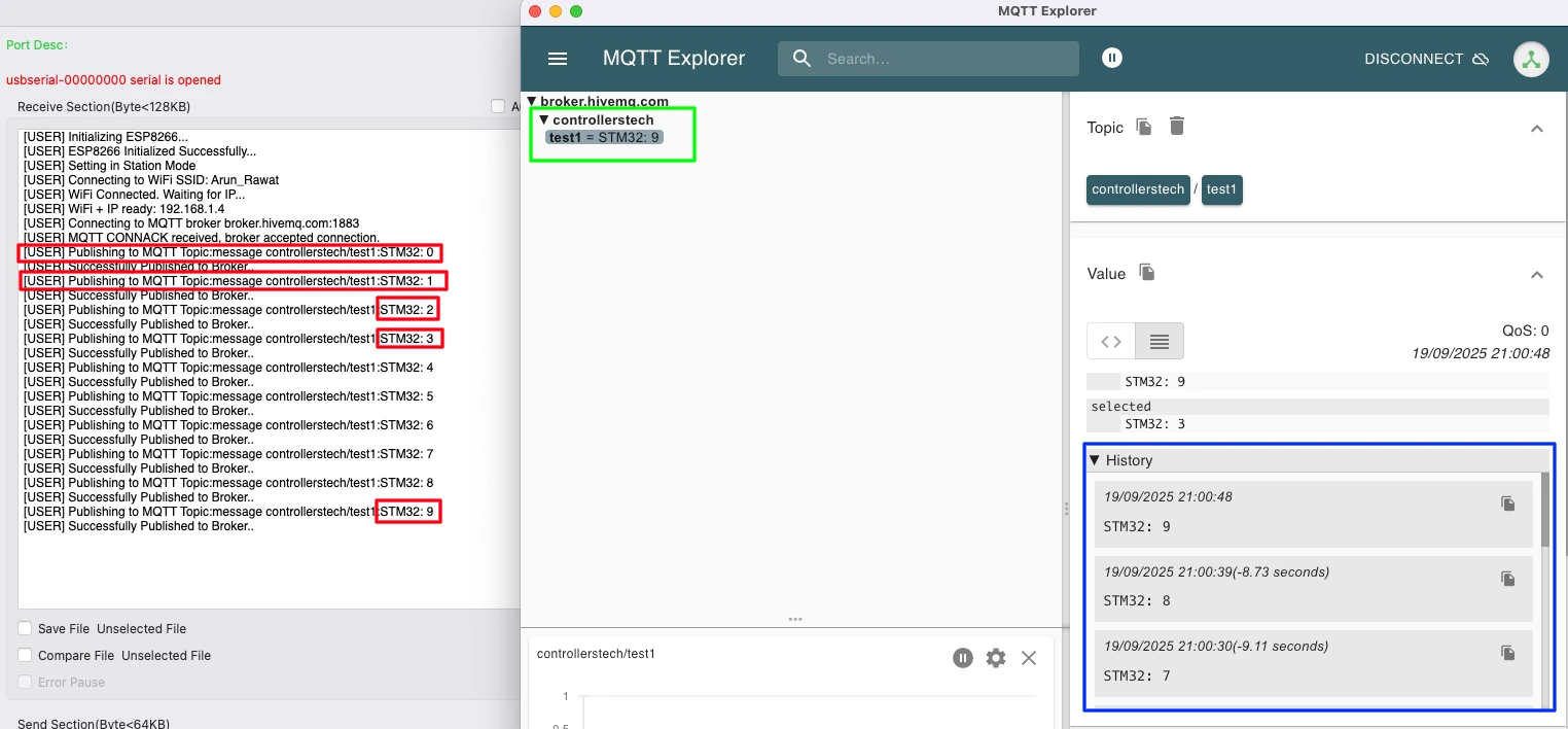
The image demonstrates the successful publishing of MQTT messages from an STM32 client to the HiveMQ broker, with verification using MQTT Explorer.
- On the left side (Serial console):
- The log shows the ESP8266 initialization, Wi-Fi connection, and successful connection to the MQTT broker.
- Multiple messages are published to the topic
controllerstech/test1with payloads likeSTM32:0,STM32:1, up toSTM32:9. - Each message is followed by a confirmation: “Successfully Published to Broker..”
- On the right side (MQTT Explorer):
- The subscribed topic
controllerstech/test1underbroker.hivemq.comdisplays the latest valueSTM32:9. - The history panel shows previously received messages (
STM32:7,STM32:8,STM32:9) with timestamps, confirming that the messages from STM32 are arriving sequentially at the broker.
- The subscribed topic
This validates that the STM32 client is continuously publishing data, and the subscriber (MQTT Explorer) is receiving it in real time.
Video Tutorial
STM32 IoT ESP8266 MQTT Video Tutorial
Our written guide covers every MQTT connect and publish step with STM32 IoT ESP8266. I’ve recorded a real-time walkthrough of connecting to your broker and publishing messages. Follow along with the code here while you watch to capture every key detail.
Watch the MQTT TutorialConclusion
In this tutorial, we successfully demonstrated how an STM32 client, together with the ESP8266 Wi-Fi module, can connect to an MQTT broker and continuously publish messages to a topic. The results verified that messages were reliably transmitted to the broker and could be observed in real time using MQTT Explorer.
This forms the foundation of MQTT communication with STM32 — you now have a working setup that can publish data streams to any MQTT-compatible broker or subscriber.
In the next tutorial, we will extend this by implementing the MQTT PINGREQ mechanism and integrating FreeRTOS to manage publishing tasks more efficiently.
Following that, we will cover subscribing to topics, enabling the STM32 client not only to publish data but also to receive messages, completing the two-way communication cycle.
STM32 IoT Tutorial Series
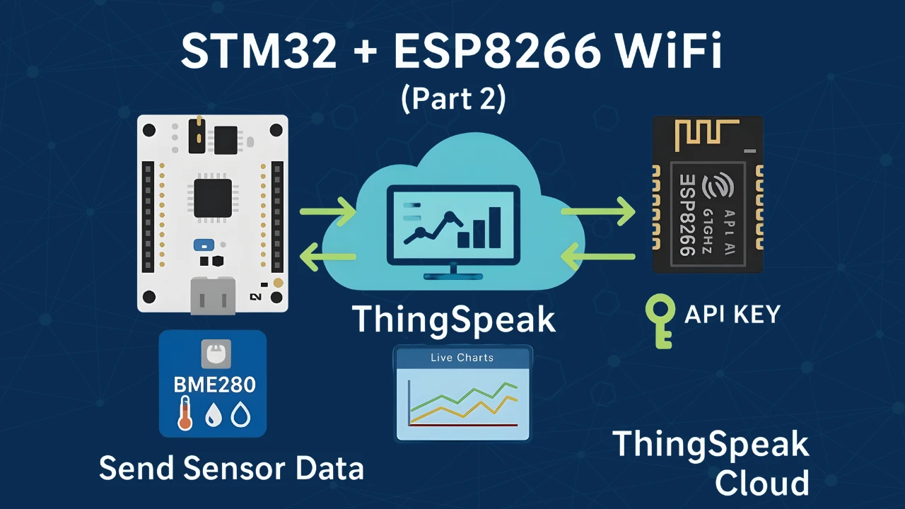
STM32 IoT with ESP8266 (Part 2): – Send Sensor Data to ThingSpeakCloud
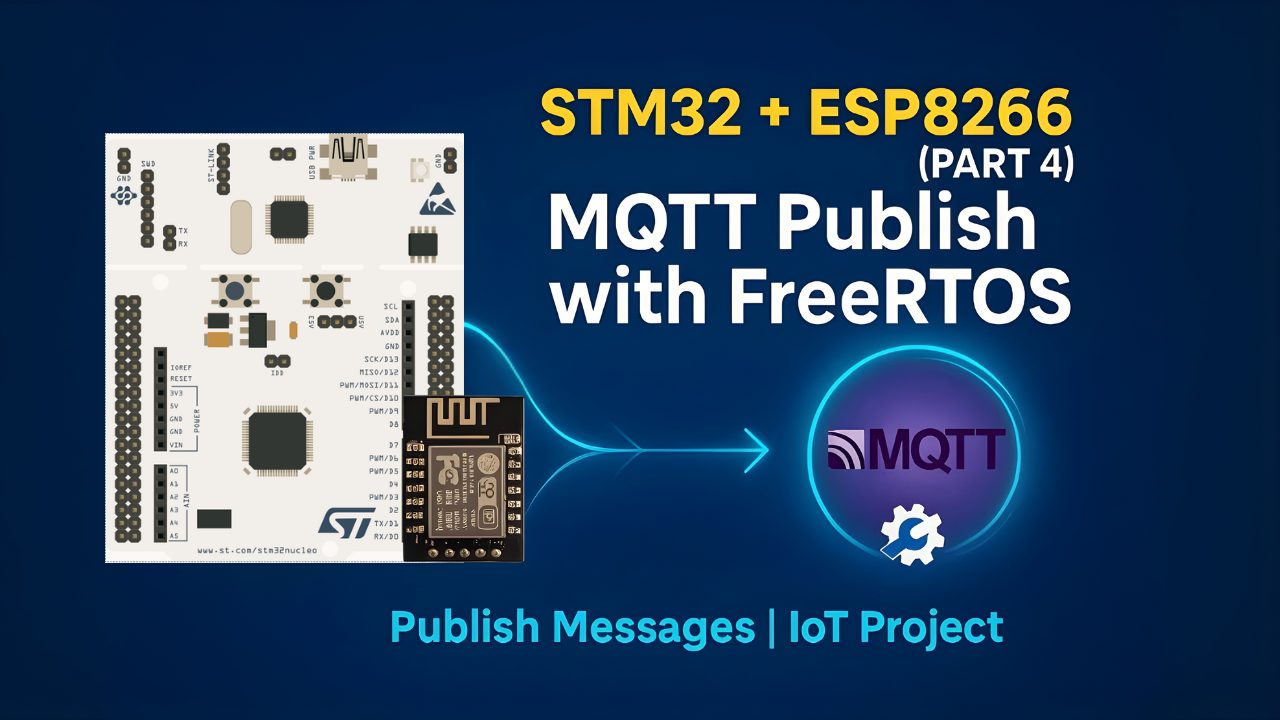
STM32 IoT with ESP8266 (Part 4): Publish MQTT messages with RTOS
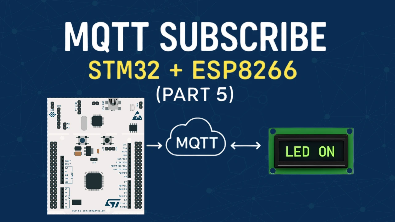
STM32 IoT Tutorial (Part 5): MQTT Subscribe with ESP8266, DMA & FreeRTOS
PROJECT DOWNLOAD
STM32 MQTT Project FAQs


thanks for the tutorial. I very glad no arduino is used here 👍. I need to find how to do with SSL/TLS connections.