ESP32 SPI || Read Data from Slave
Master ESP32 SPI Part 2: Configure bus to read data from a W25Q flash slave, retrieve its ID, and access downloadable project files. Step-by-step guide.
Recommended Resources:
This is the 6th tutorial in the ESP32 series using the espressif-IDF and 2nd in the mini series covering the SPI peripheral in ESP32. In the previous tutorial, I have covered how to configure the SPI in master mode and how to transmit the data.
You must take a look the following resource before continuing:
Today I am going to connect W25Q SPI flash memory as a slave device with the ESP32. We will see how to connect the W25Q with the ESP32 and how to read the ID of the slave device.
VIDEO TUTORIAL
You can check the video to see the complete explanation and working of this project.
Introducing the SPI peripheral in ESP32
The ESP32 microcontroller features multiple SPI (Serial Peripheral Interface) peripherals, which are versatile and efficient for high-speed communication with a wide range of devices such as sensors, displays, memory chips, and other microcontrollers. It supports full-duplex data transfers and can operate in both master and slave modes. The SPI drivers in the ESP-IDF (Espressif IoT Development Framework) provide flexible APIs for configuration, queuing transactions, and DMA-based transfers for optimal performance.
Some important features of SPI peripherals are:
- Flexible Communication Modes: Supports master and slave modes, full-duplex and half-duplex communication, and both 3-wire and 4-wire SPI.
- High-Speed Data Transfer: Operates at clock speeds up to 80 MHz with support for DMA and FIFO buffers for efficient data handling.
- Multiple SPI Channels: Includes up to 4 SPI peripherals (SPI0–SPI3), with HSPI and VSPI available for general use.
- Advanced Configuration: Offers configurable clock polarity/phase (CPOL/CPHA), auto chip-select control, and ESP-IDF APIs for queue-based asynchronous transfers.
I am using the ESP32 wroom Development board with 38 pins. Below is the image showing the pinout and available SPI instances ion this board.
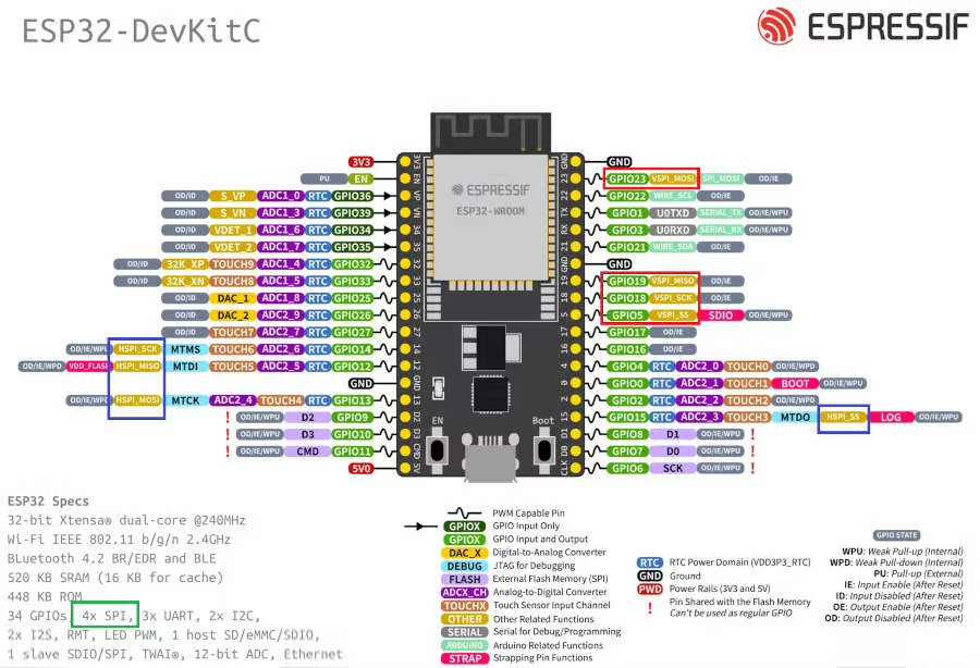
The ESP32 microcontroller has four Serial Peripheral Interface (SPI) ports: SPI0, SPI1, HSPI (SPI2), and VSPI (SPI3).
- SPI0 and SPI1: Used internally to communicate with the ESP32’s flash memory. These ports share the same SPI bus signals, and an arbiter determines which can access the bus.
- HSPI (SPI2) and VSPI (SPI3): General purpose SPI drivers that users can access. These ports have independent bus signals, and each bus can drive up to three SPI slaves.
The image above shows the pins availability for the VSPI (Red Box) and HSPI (Blue Box). We can use either of these instances to avoid any conflict with the internal flash memory.
WIRING DIAGRAM
Below is the image showing the connection between ESP32 and W25Q flash memory.
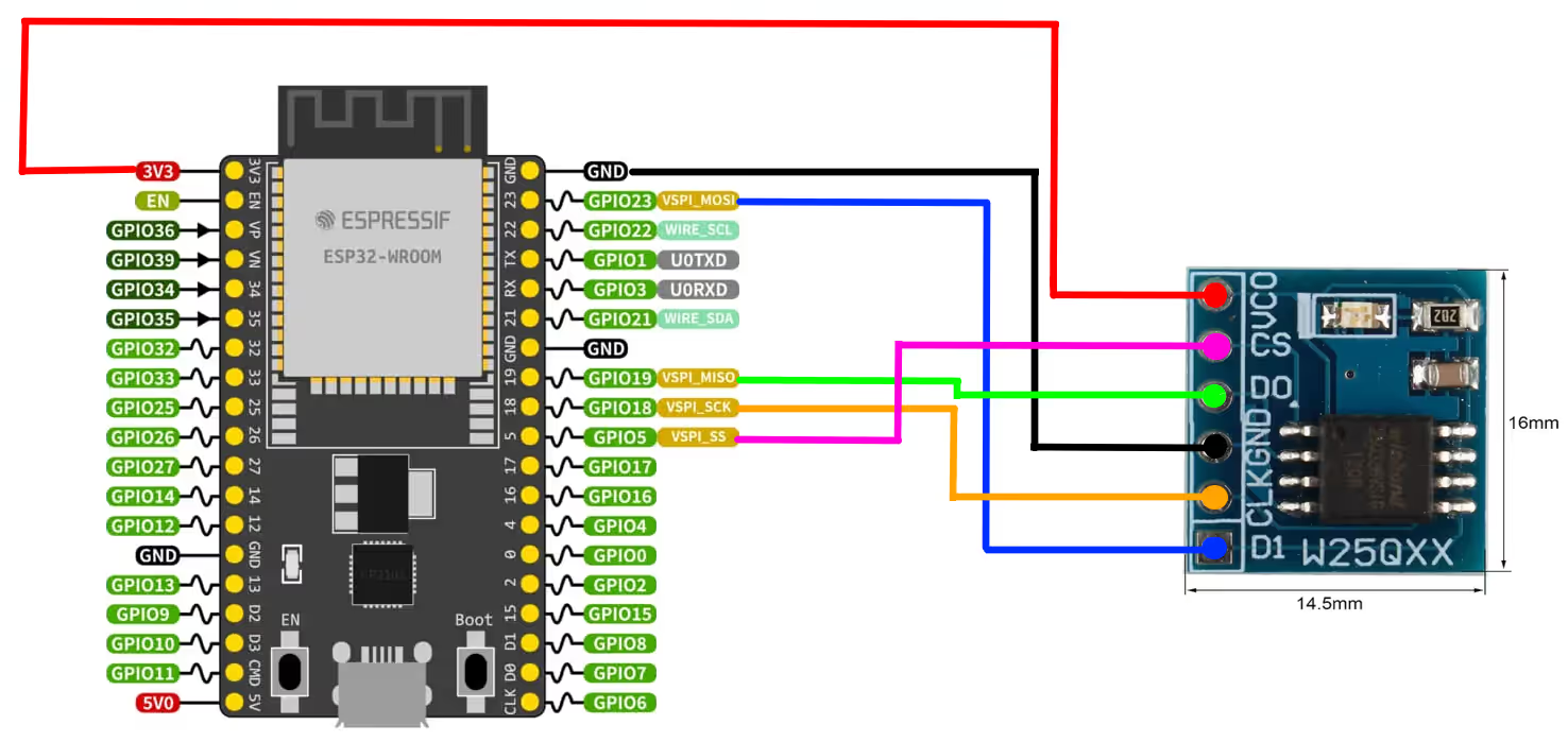
As you can see above, the W25Q flash is powered with 3.3V from the ESP32.
| Flash Pin | Connected to ESP32 Pin | ESP32 Signal Name |
|---|---|---|
| CS | GPIO5 | VSPI_SS |
| DO (Data Out) | GPIO19 | VSPI_MISO |
| CLK | GPIO18 | VSPI_SCK |
| DI (Data In) | GPIO23 | VSPI_MOSI |
Today we will only read the ID of the W25Q flash memory. Whereas in the next tutorial we will see how to write and read the data from this memory.
What is W25Q’s ID ?
Below is the image showing the ID of the W25Q32.
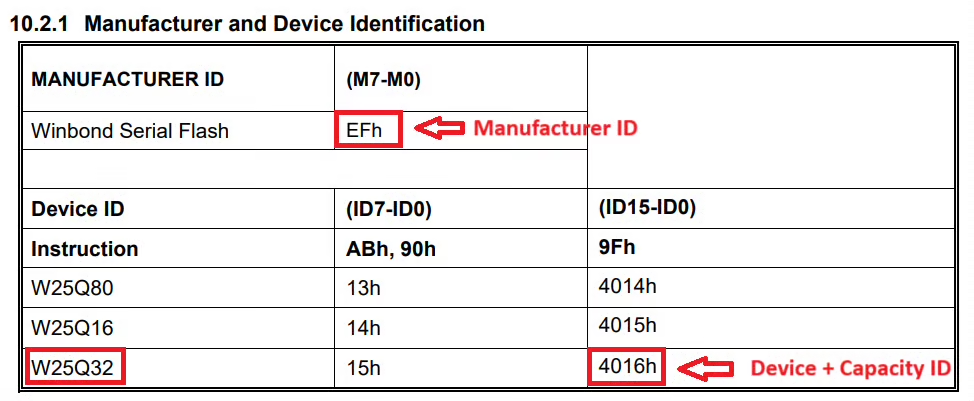
The ID is a combination of manufacturer ID, Device ID and Capacity ID. When combined, the 24 bit ID for the W25Q32 will be 0xEF4016. We will read this ID from the slave device.
As per the datasheet of the W25Q, the register 0x9F is used to read the ID of the device.
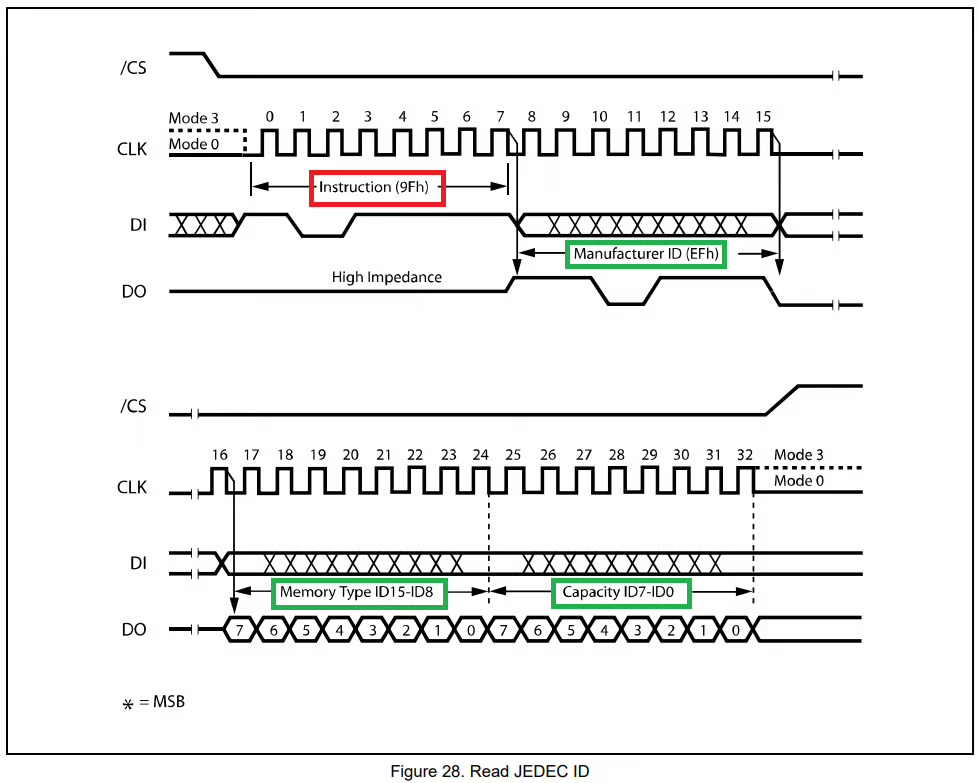
As demonstrated by the clock diagram above, when the Register address 0x9F is sent by the master, the W25Q responds with 3 bytes data. This first byte is the Manufacturer ID, second byte is Memory Type ID and the third byte is Capacity ID.
THE CODE
We have already covered the configuration and how to transmit the data in the previous tutorial.
SPI Receive Function
We will write a new function to receive the data from the slave device.
void spi_receive (uint64_t Addr, size_t addrLen, uint8_t *buffertoStore, size_t dataLen)
{The parameters of the spi_receive function are as follows:
- @Addr is the 64 bit address of the memory inside the slave device, where we want to read the data from.
- @addrLen is the number of bytes of the address data. Not all the devices requires 64 bits for the memory address, therefore addrLen will control how many address bytes we want to send.
- @buffertoStore is the pointer to the buffer where the received data will be stored.
- @dataLen is the number of data bytes we want to receive from the slave device.
Inside this function we first need to define a SPI Transaction structure, just like we did while transmitting the data.
spi_transaction_t trans;
memset(&trans, 0, sizeof(spi_transaction_t));The SPI Transaction structure should hold all the information about the transaction we want to perform on the SPI bus. It holds information like the transmit and receiving buffers, the flags, the size of the data to be transmitted or received, etc. You can read about this structure in detail in the ESP docs.
We want to transmit the address and receive the data from the slave device. By default the SPI is configured in full duplex mode. Hence while the ESP32 transmits the data on the MOSI line, it also reads the data on the MISO line. But we want the ESP32 to not read the MISO line while the address is being transmitted. This is because the slave device will only transmit the data after it has received the address from the master.
The ESP32 does not read the data on the MISO line when the command and address bits are being transferred. Therefore we can use either the command or address parameter of the transaction structure to send the register address (0x9F) of the slave device.
trans.flags = SPI_TRANS_VARIABLE_ADDR;
trans.addr = Addr;
trans.length = dataLen*8;
trans.rx_buffer = buffertoStore;While using the command or address parameters, the SPI_TRANS_VARIABLE_ADDR flag or SPI_TRANS_VARIABLE_CMD flag must be set in the transaction structure. This is because we have configured the size of the command and address bits in the device configuration to 0. Setting these flags will allow us to configured the size manually, but in the external transaction structure.
- The addr member of the transaction structure stores the address data, which is passed in the function’s parameter.
- rx_buffer is the pointer to the buffer where the received data will be stored.
- length is the total data length in bits. It includes the length of the data to be transmitted and the data to be received as well. Since we are transmitting address (not data), only the length of the data to be received will be included here.
Now we will define an external transaction structure. This structure contains the information about the size of the command and address bits.
spi_transaction_ext_t trans_ext;
memset(&trans_ext, 0, sizeof(spi_transaction_ext_t));
trans_ext.address_bits = addrLen*8;
trans_ext.base = trans;The member address_bits of this structure stores the size of the address data, but in bits. The variable addrLen is present in the function’s parameter and it represents the number of address bytes we want to send.
The member base of this structure points to the original transaction. This way this external transaction structure stores all the information of the original transaction, along with the size of address_bits as well.
Once the transaction structures are populated with data, we will transmit it via the SPI.
if (spi_device_transmit(spi_handle, (spi_transaction_t *)&trans_ext) != ESP_OK)
{
printf("writing error\n");
}
}Note that we are sending the external transaction since it contains the information about the original transaction, along with the size of address_bits as well.
Combining the above data, below id the final receive function.
void spi_receive (uint64_t Addr, size_t addrLen, uint8_t *buffertoStore, size_t dataLen)
{
	spi_transaction_t trans;
	memset(&trans, 0, sizeof(spi_transaction_t));
spi_transaction_ext_t trans_ext;
memset(&trans_ext, 0, sizeof(spi_transaction_ext_t));
	trans.flags = SPI_TRANS_VARIABLE_ADDR;
	trans.addr = Addr;
	trans.length = dataLen*8;
	trans.rx_buffer = buffertoStore;
trans_ext.address_bits = addrLen*8;
trans_ext.base = trans;
	if (spi_device_transmit(spi_handle, (spi_transaction_t *)&trans_ext) != ESP_OK)
	{
		printf("writing error\n");
	}
}The main function
ide the main function, we will simply initialize the SPI and then keep reading the ID every second.
uint8_t Address = 0x9F;
uint8_t RxData[10];
unsigned long int ID = 0;

void app_main(void)
{
  SPI_Init();
  while (1)
  {
	SPI_Receive(Address, 1, RxData, 3);
	ID = (RxData[0]<<16)|(RxData[1]<<8)|RxData[2];
	printf("ID = %lX\n", ID);
	sleep(1);
  }
}Here we will first initialize the SPI in the main function. Then the function spi_receive will be called in the while loop, to receive the ID every second.
Here Address is the register address (0x9F) where we want to read the ID from, 1 is the number of Address bytes we are transmitting, RxBuffer is the array where the received data will be stored into and 3 is the number of data bytes we want to read from the slave.
After reading the 3 ID bytes we will combine them to make a single 24bit ID and then print the ID on the console.
RESULT
Below is the image showing the output on the console.
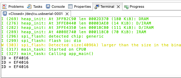
As shown in the image above, the ID is 0xEF4016. This is the same ID that we were expecting from the device.
PROJECT DOWNLOAD

